Networking
This week is one of the most difficult weeks for me (following input week) and took me a very long time to get everything right. Even just following the exact same steps, I ran into so many little bugs. A word of warning to whomever is working on networking week: start early! A huge shout out to our amazing TAs: Anthony, Zach, Eyal, Cedric.
Board design and milling
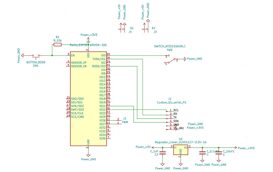
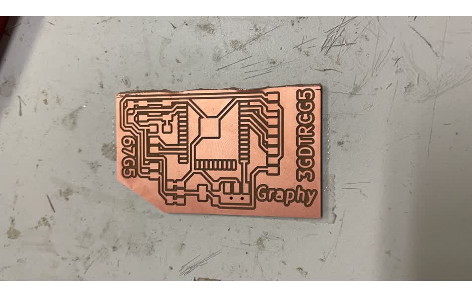
Working towards my final project, I want to have a pair of networked brush communicating over WiFi so that it can be truly "tele"-presence. To start, I looked into the pin-outs of the ESP32-Wroom module. From the input and output week, I know the critical importance of finding the right pins, especially for I2C communication. This guide has the comprehensive description of each pin's function. pin 21 (SDA) and 22 (SCL) are for I2C communication with my IMU, pin 26 and 27 are PWM pins for my two servos. Because the TX/RX pins are sandwiched right between the I2C pins, I decided to make my own headers to avoid adding zero resistors. I etched text below my header pads so that I know their corresponding functions. I also added power and ground connections for my sensor (3V)/actuator (5V). A quick note as I learned about this from others in the class, the pads of the ESP32's footprint in the FAB library is too big. Make sure to modify SizeY (width) to 0.6mm instead.
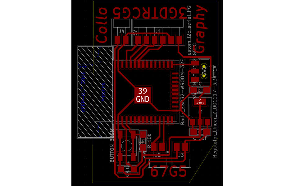
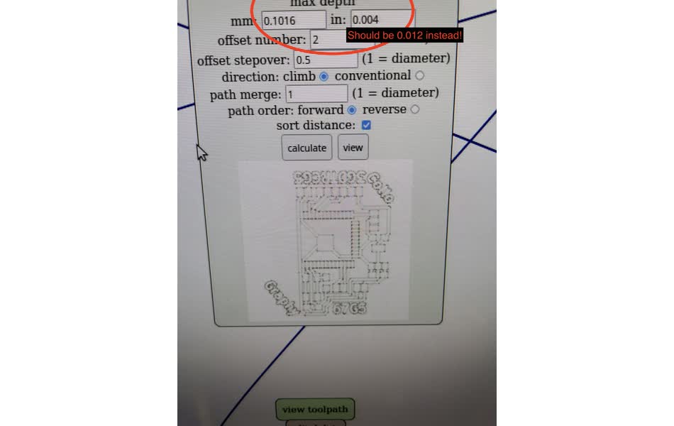
Time to mill the board. Even after so many times of milling, I still encountered some problems and made a couple of silly errors. (1) The Mods was not cooperating, so I had to reset and restart the system a couple of times. (2) I usually set the max mill depth to be 0.012in instead of 0.004in to get clean traces. I accidently swapped the two values, which prevented the mods from generating the path preview. This error alone cost me a really long time to notice. (3) I didn't know you were supposed to make sure there is nothing underneath the esp32 antenna. Later you will see that I had to use an exacto knife to etch and then chip off a part of the board. Silly me also made the same mistake twice so both of my boards have chipped off edge, which I will consider as a feature of my design lol.
Hardware failures
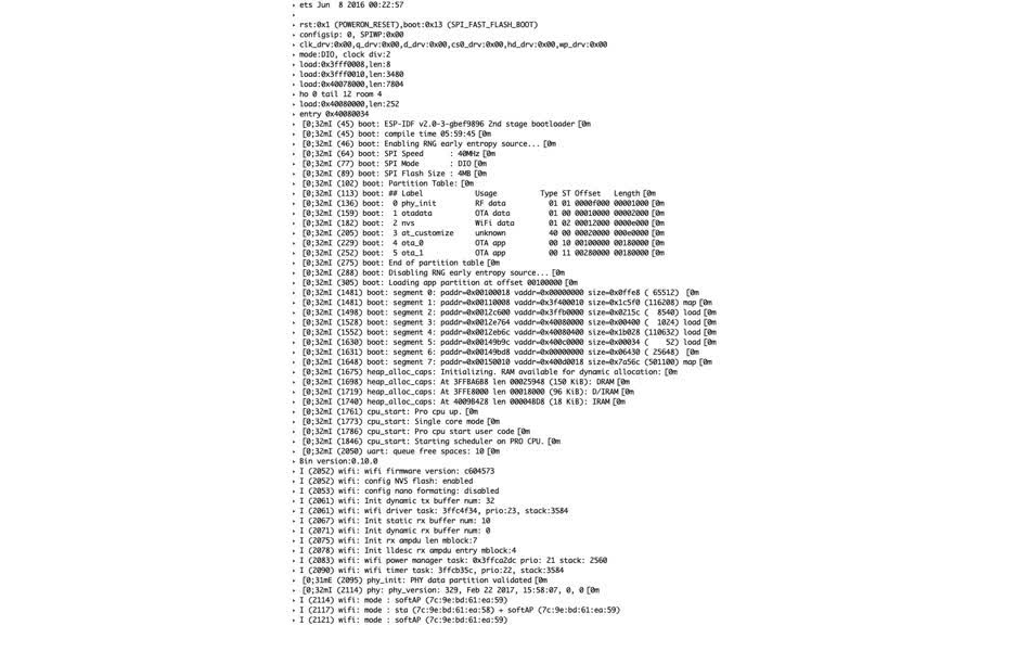
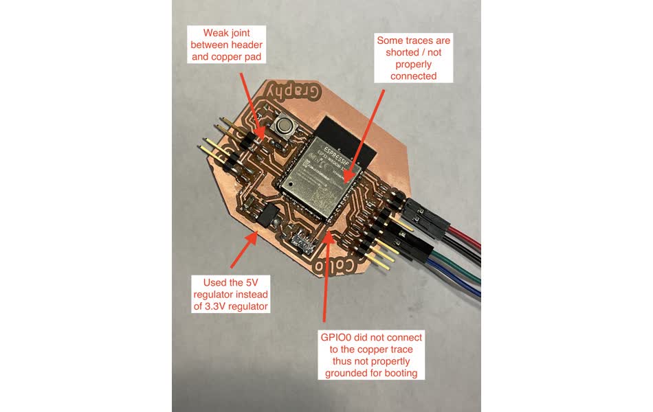
Just as I thought I was good to go, little did I know the following week I suffered from a combination of soldering mistakes I made. To program the ESP32-Wroom, you would first need to ground the GPIO0 and press the reset button so that the board is ready for receive the code. When I pressed the button, the serial vomits a chunck of texts but nothing saying "ready for download". I checked the continuity of GPIO and GND and for sanity checked everything else too, which is when I found out about my first soldering mistake: some of the esp32 pins are shorted. However, the error is still unresolved after that. I went to Anthony for help and discovered so many little mistakes. The most critical one being GPIO0 pin isn't actually connected to the copper trace underneath! I had only checked the traces' continuity. No wonder the board was not ready for download. Some other mistakes were found during this debugging was (1) I grabbed the 5V regulator instead of the 3.3V since they look identical except for the tiny text on top. (2) My headers were not properly joined with the copper pads, which is just quite bad.
WiFi Access Point and UDP communication
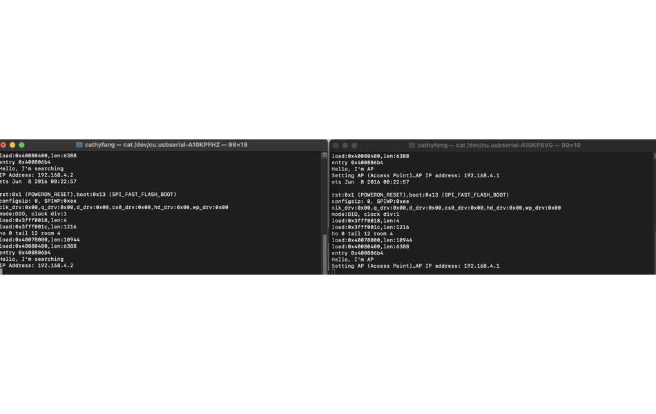
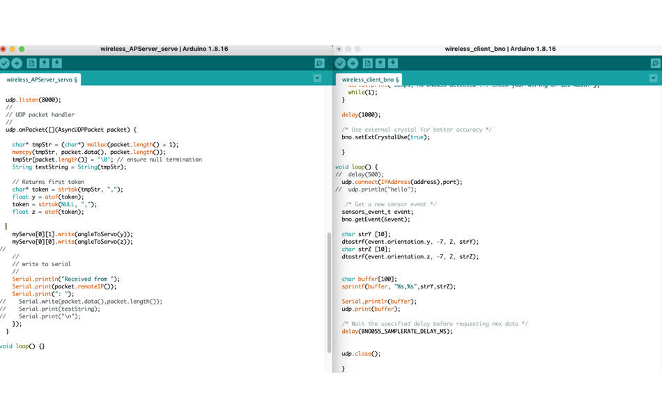
Since I know that the Media Lab wifi will be super crowded with traffic during the demo day, I decided to make one of my ESP32s an Access Point, which is basically a wifi router that other devices could use. I just followed this tutorial. Initially, it would not connect, which is when I found out about the error in the design of my board (see earlier text about chipping off part of the board behind the antenna). For the other board, it just needs to enter the corresponding ssid and password as if it's just connecting a normal network. After the two boards can find each other, now I need to send data from one to the other. For that, I used UDP because it's quite simple to set up (following Neil's tutorial) and I don't care so much about package loss. What I am sending is orientation data from the IMU to the other. Since upd sends/reads bytes, I needed to do a series of conversion between variables: (1) on the sender end: convert the orientation float values to string using dtostrf() print multiple variables into one string using sprintf() (2) on the receiver end: parce the async udp packet in byte to a string using this stackoverflow solution and then use strtok() to separate the values at the delimiter and use atof() to convert the string to a float.