Output
Again to build towards my final project, I need to control two servo motors that drive the tip of the brush. Details about the design of the motor attachment will be on my final project page. For this week, I just want to make sure the board I made has enough PWM pins for the servo. Checking the pinout page made by Adrian Torres , it has a total of 6 PWM pins, 2 of which are SCL and SDA (for the BNO055). Because I didn't want to make another board, for testing purposes, I just borrowed the same pins I used last week, SCL and SDA (pin 6 and 7). The code compiles and runs!

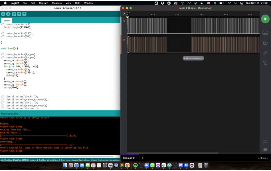
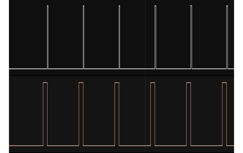
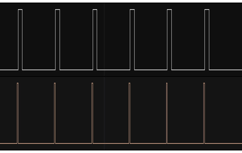
I'm loving the digital analyzer trick. Here I made the two motors go the opposite angles and you can clearly see it in the signals!
Here are some fun clips of driving the brush. For the final project, the servo angles will be controlled by the IMU so not some crazy movement like this.