Project 01 Exploring Few Ideas (and associated 2D models) Towards the Final Project
Smart Electronic Textiles- Towards a Personalized Healthcare System
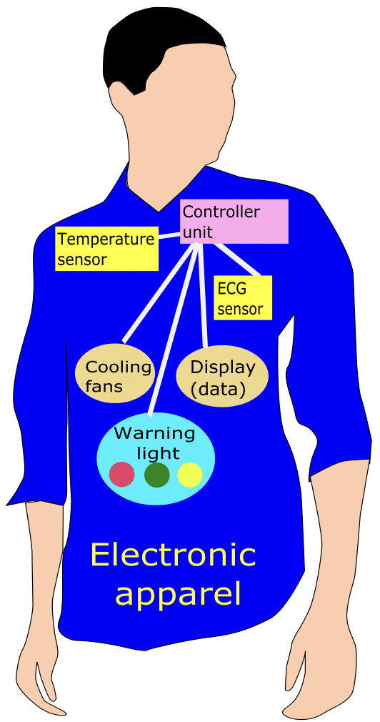
Idea 01: The device is expected to sense different physiological signals and display and warn the user using different actuators/transducers
Progress:
(a) Talking to a TA & moving to a new micro-controller: I loved all the TAs. One day, I met Andres during his office hours and shared my project plan. Before going to Mexico for his research project, we had the
opportunity to talk about my project briefly. I wanted to switch from the ARM series' ATTINY 412 MC (microcntroller) to 3216 because of higher number
of pinouts. Andres also thought it would be a good idea. He adviced me and helped me out in this regard. I really appreciate all the support and suggestions Andres gave me.
(b) Deciding my final project: Finally, I decided to make an electronic device that could sense body temperature and humidity in real time and display it using a LCD display.
Unlike shwon in the image above, there will be only a sensor and a LCD display in my final device. I may also add a piezo-buzzer and/or an array of light emitting diodes as a medium of warning/alarming
the user if the temperature/humidity surpasses any given threshold set by the user. In summary, it will be a device to monitor part of the human thermoregulatory system
by monitoring temperature of any target region of the body along with the associated humidity conditions.
(c) Areas of applications: The fundamental purpose of the project is to build an electronic device using off-the-shelf electronics. Such an important physiological signal could help users, like soldiers or firefighters,
monitor their body temperature during their activity or field operations. If added with a bluetooth or wireless device, the user-body conditions could
be monitored from a remote controlling center. In case of any field-emergency, they can deploy additional human resources to save the user of my device.
Such a device could come in handy for montoring thermal-work strain monitoring. Also, such a system can be used for immobile patients (e.g., patients suffering from paraplegia or pressure ulcer) as the alarm/alert-system can call for
help from people nearby.
(d) Literature survey: This is my first time making my own electronic device. I am excited to pursue the idea. However, I should have also explore few literatuers to figure out
what has been done in this field similar to my idea. In that case, I could have build upon the previous works. So, I started to explore previous works and see
what really have been proposed in this case. I did some literaure survey briefly and found similar commerical products but didn't see any temperature monitoring LCD dosplay
in those products or any alert system. Hence, in my case, I will build the missing pieces so that the user him/herself can visualize their physical signal. The inspiration to build device came
from my previous research works on wearable joule heaters that I worked on during my MSc. I encountered that paraplegic patients often burn their buttocks while being subjected to joule heating
textile products as they suffer from impairments in "motor or sensory function of the lower extremities" due to paraplegia. Most of the wearable joule heating products just heat but they do not monitor the
skin temperature of the user. In this project, I develop a device that would monitor the temperature of the textiles next to the human skin (i.e., the clothes they are wearing) and will alert user if the textile temperature
crosses their set temperature; and, I programmed 28 degree celcius to be the threshold point.
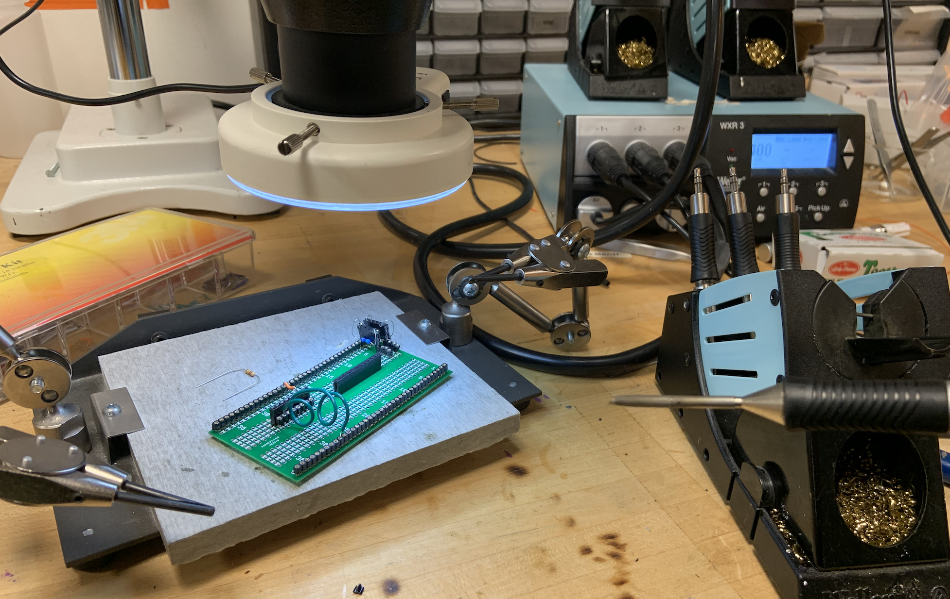
(e) Starting to build the project: So I started to work on the ATTINY 3216 from Project #10. As shown in project #10, I made the UPDI adapter to program the MC using a
USB to TTL serial 3.3V UART converter cable with FTDI chip terminated by 6 way header. Since, I already used the DHT_11 in Project #09,
I have to combine the configuration with the I2C interfaced LCD display, but for a new MC, i.e., the ATTIMY 3216 in this case. I also tried differnt actuators
transducers with the circuit along with sensors. For example, if the sensor input data (bending value/temperature hike/ distance of an object) crosses a certain threshold,
the RGB LED will turn from green/blue to red or the piezo buzzer will start beeping to alert the user. Finally, the project seems slowly coming to a matured phase for me.
I have faced lots of challenges while working towards the project as detailed in Projects 09-10; however, I was always in contact
with Andres through emails and slowly worked my way towards my final project. The best part was figuring out the need of applying the two ~4.7k pull-up resistors.
Starting the final project
Project goal:
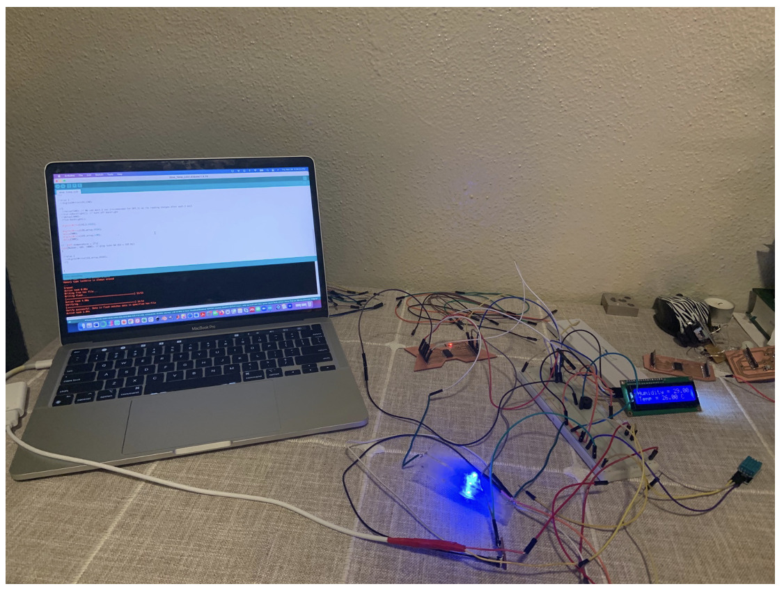
I plan to make a circuit that will have the DHT_11sensor that will read body's temperature/humidity signal. The PCB will also have LCD to display the temperature/humidity values.
Further, I want to add an array of blue LED lights which will turn on/off at regular interval. It is for a better visual appearance for the product. The product will also have a piezo-buzzer that
will turn on whenever the temperature will surpass a certain threshold to alert the user and surrounding caregiver.
Materials:
1. LCD with I2C communication interface backpack
2. Piezo buzzer
3. DHT_11 temperature and humidity sensor
4. ATTINY 3216 AVR Micocontroller and Arduino Uno
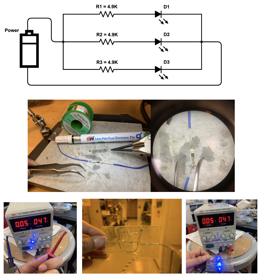
5. An array of three blue LEDs connected in parallel. Since one LED requires 3V to drive, meaning 3 LEDs would require 9Vs, an array of LEDs in series were fabricated with each of the LEDs has a current limiting 4.9K ohm resistor connected to it in series. The LEDs and resistors were soldered and laminated between 3M synthetic films to hold the structure of the array.
6. Built-in RED LED in series with a 1K ohm integrated to a ATTINY 3216 microcontroller (MC). The built-in LED is connected to pin 19 of the ATTINY. There is a capacitor in between GRND and VCC pin of the MC. The capacitance of the capacitor is 1 micro faraday.
7. One adapter to connect with a 6-pin FTDI cable (3.3V) to program the MC with its built-in UPDI pin no 16. The architecture of the adapter is provided in PROJECT #10 (OUTPUT DEVICE week).
8. Power supply of 5V through a USB to serial converter cable. The power supply cable was personalized based on the requirement of pinouts.
My Code:
#include // Library for I2C communication
#include // Library for LCD
#include // Library for DHT sensors (e.g., DHT_11, _22...)
dht DHT;
#define DHT11_PIN 2 // Connecting to Arduino Pin 2 for the DHT_11 sensor
LiquidCrystal_I2C lcd(0x27,16,2); // set the LCD address to 0x27 for a 16 chars and 2 line display
#define LED_1 16
#define LED_array 3
#define Buzzer 5
void setup(){
Serial.begin(9600);
lcd.init(); // initialize the lcd
lcd.backlight(); // turn on backlight.
lcd.begin(16, 2);
pinMode(LED_1,OUTPUT);
pinMode(LED_array,OUTPUT);
pinMode(Buzzer, OUTPUT);
}
if (DHT.temperature > 27){
tone(Buzzer, 165, 1000); // play tone 40 (E3 = 165 Hz)
}
}
LED Array fabrication (in series configuration):
To give a good look and ensure the sketch is running through my ATTINY 3216, I wanted to add an array of blinky blue LEDs to my device.
Hence, I added three LEDS and three associated 4.9k ohm resistors in series as seen in the image below. Since, each LED requires 3V of power,
indicating 9V if added in series, I decided to configure the array rather in paraller architecture so that the reqired power voltage remains below 5V.
Otherwise, the would have been a power mismatch between my PCB/LCD and LED array and a higher voltage would eventually burn my PCB-sensor-piezo-LCD circuit architecture.
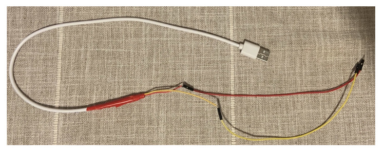
Converting a micro USB cable into suitable connectors for 5V power supply cord
Since there is no 5V battery, I decided to use the power from USB ports that usually supplies 5V. One such source was the USB port of computers.
However, I didn't have the connector. So, I took one USB micro cable and cut it to expose the individual male connectors to the breadboard for supplying power from a MacBook.
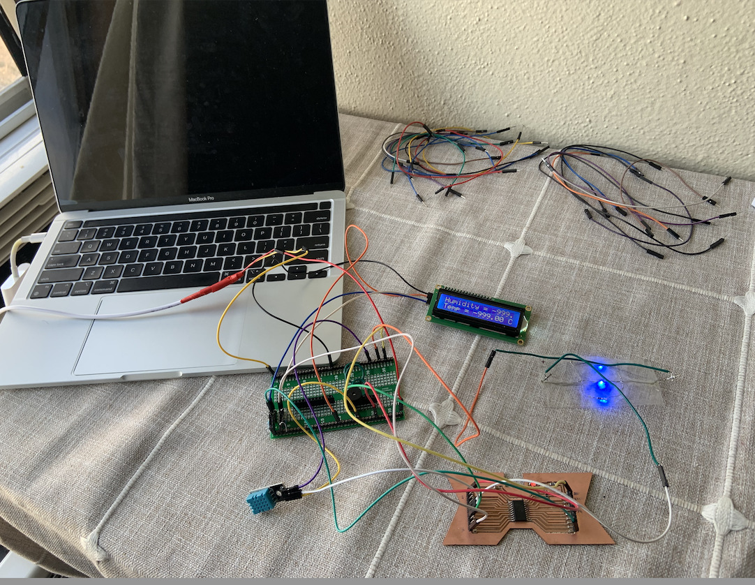
Flashing my ATTINY PCB with the programming code & trying out using the breadboard
Video clips
Challenges that I am facing now:
1. How can I replace the power supplier 5V USB to serial cable into a battery and integrate that into my board. May be I should make a separate breakput board to replace the breadboard and add a battery (5V coin cell).
2. How can I embed/mount the boards and associated circuitries onto a textiles. I thoght of making individual 3D-printed cases/enclosures and molded/caseted structures to enclose my circuitry. It will not only provide a better aesthetic but also will provide safety from external/mechanical deformation.
3. How can I add my flexible LED-array and how can I protect it from damage. May be I should sew/bond it at the inner-face of the apparel with a 3D printed backing attached to the array
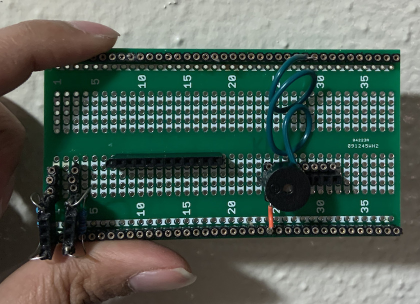
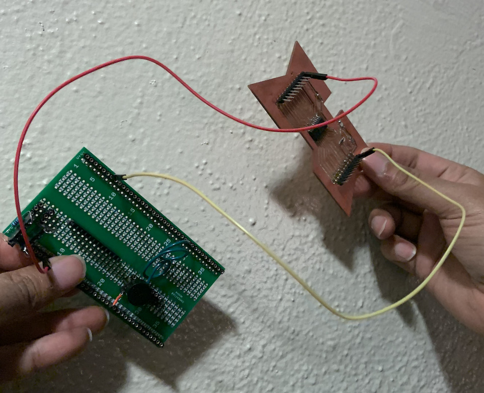
Making a custom pull-up resistor board:
To replace the large breadboard, I decided to make a custom breadboard of my own and embeding header pins and soldering them. I chose a board that has a similar dimension to that of my milled PCB baord housing the ATTINY 3216. The idea is to connect/glue these two boards togther with their bottom-surface facing each other.
I added two 4.9K ohm pull-up resistors on this custom board for the I2C interfaced LCD. Additionally, necessary connections were made to ground the piezo-buzzer so that when
piezo buzzer is embedded on the board,no separate jumper wires are required for ground connection.
Video clips
Next, I have to think of a cordless power source that can be directly added to the modules all together so that there is no need of any wired power source.
Trials on human subject and conceptualizing the wearable:
I thought of trying the device onto a t-shirt by loosely clinging to it just to have an idea how it would look like and to think of a way for packaging the whole device.
I plan to make a 3D model for the packaging case. I may eith laser cut the 2D pieces of the 3D model or I can directly 3D print it. However, it would depend on the outlook of
the final product. Molding/castiing could be another approach for making the packaging case/house.
Meeting with another TA, Jake:
Accoridng to Jake, Neil may not like too much jumper wires in my current setting. So, I decided to design a completely new PCB that would combine both of my boards (MC board and Power source board) in one.
I plan to start the documentation in my "Final Project" page and not in this page.
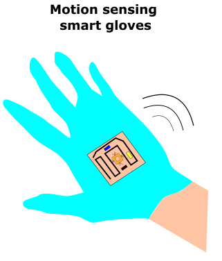
Idea 02: Hand gesture sensing smart gloves for controlling a robotic arm or therapeutic applications.
Progress:
I wanted to pursue this idea and already 3D printed parts of a finger. Also, read few relevant literatures supporting my project theme.
However, I figured out that I do not have that much time to work on it. So, I abandoned my idea and, may be, in future, I will pursue this idea.