Electronics Design
Tools: Roland SRM-20 mill, soldering station, DMM, oscilloscope
Group Assignment (Test Equipment):
I probed continuity using the continuity buzzer on the multimeter to verify connections. I showed others how to use the oscilloscope by measuring the calibration square wave.

Individual Assignment:
Useless POS Cube:
I was a bit ambitious in my design, as I chose to make a cube with milled PCB panels. I was hoping to design the board in such a way that I could form a tight joint between faces of the
cube and use solder to mechanically join the faces while also connecting traces running in the interior of the cube. To make my life more miserable, I designed a two-layer board with vias.
My original concept was to control an RGB LED with a capacitive touch sensor milled into the outside face of the board and include echo capability.
tldr; I successfully soldered the cube together and verified continuity of all traces, but realized that I used the wrong LM3480 and am seeing the dropout voltage at the regulator output. Rework in progress..
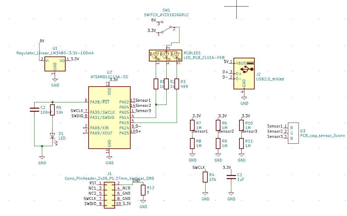
Schematic Design:
I used KiCad to make a relatively simple schematic based on the example boards on the website. I like the KiCad workflow for its hotkeys, but I'm sure that you can just as easily configure Eagle with hotkeys.
It's nice that Eagle makes some of the layout easier to revise. Anyways, I ended up redrawing the footprint for the USB pins (before it was posted on Gitlab)
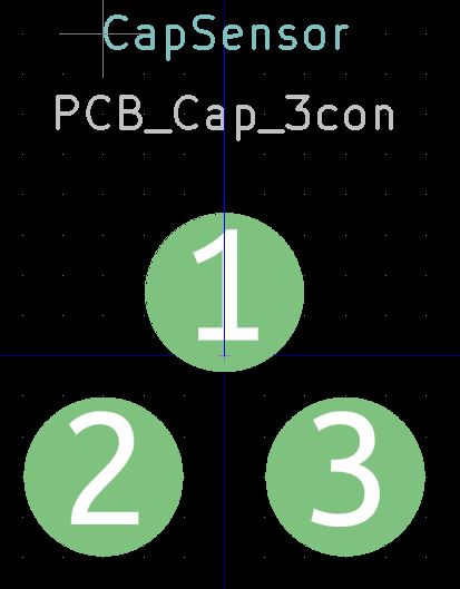
as well as making a footprint for the capacitive touch sensor. To sense touch, I was hoping to sample the RC response to detect if a finger capacitance was detected (RC=~1us) then modulate the RGB
based on the response. I find it good practice to group the schematic by function (power, mcu, sensors, connectors) then use net labels to connect things. If there's an analog
ciruit part in the schematic, however, I find it easier to draw with wires for easy future reference.
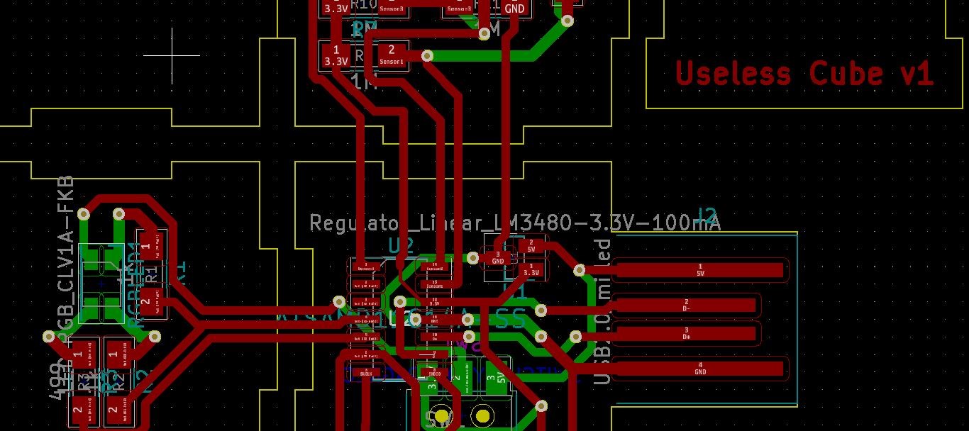
Layout:
I enjoy playing some loud techno to enter the zone during tedious and occasionally satisfying activities like layout and assembly. Because I had already committed to
making the stupid cube with two-layers, I just used vias to complete the routing. I used them as minimally as I could and used one zero Ohm jumper.
Next, to make the connections between cube faces, I just made sure to route the traces straight across the boundry. Giving some extra room between faces, I drew the drill outlines.
I made sure that my design was centered, square, and symmetrical, so that I could add simple alignment features in the corners without thinking about it too much.
I also made sure that the layer two vias and pads were oversized to account for alignment tolerance.
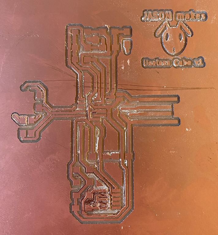
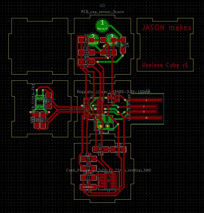 Milling:
Milling my board was a pain. I understood that making a two layer board involves having to flip and re-align the cutout, yet I persisted.
I used Inkscape to separate the layers into drawing files and widen some vias for alignment tolerance. Honestly, I should have just designed a simple board and moved on with my life.
It had no trouble converting in mods, but the board took 20 minutes to mill. Combined with the dwindling supply of 1/64 end mills and the tool reservations through the night, I really only had
two chances to mill. Furthermore, I had to mill the traces, mill the vias with the 1/64 mill, mill the outline with the 1/32 mill, flip and realign the pattern and mill again with 1/64 without angrying other users.
Finally I had to add the rivets. I ended up getting the traces, vias, and outline milled perfectly. To mill side two, I used the frame produced in the outline and taped down the pieces as well as I could.
I then lined up the end mill to my alignment mark, manually corrected rotation by eye, and hit start. TADA! I was 1 mm off, and it ruined my board. Square 1 again..
Milling:
Milling my board was a pain. I understood that making a two layer board involves having to flip and re-align the cutout, yet I persisted.
I used Inkscape to separate the layers into drawing files and widen some vias for alignment tolerance. Honestly, I should have just designed a simple board and moved on with my life.
It had no trouble converting in mods, but the board took 20 minutes to mill. Combined with the dwindling supply of 1/64 end mills and the tool reservations through the night, I really only had
two chances to mill. Furthermore, I had to mill the traces, mill the vias with the 1/64 mill, mill the outline with the 1/32 mill, flip and realign the pattern and mill again with 1/64 without angrying other users.
Finally I had to add the rivets. I ended up getting the traces, vias, and outline milled perfectly. To mill side two, I used the frame produced in the outline and taped down the pieces as well as I could.
I then lined up the end mill to my alignment mark, manually corrected rotation by eye, and hit start. TADA! I was 1 mm off, and it ruined my board. Square 1 again..
Manual Milling:
In a fit of frustration, I started to see if I could find any way to salvage my board and I realized that I just had to isolate the copper around the vias.
I could make connections again with some small wires. Using a razor blade at a shallow angle worked really well. It took me around 30min to mentally relayout layer two, and another 30 min cut the copper, but I had a chance.

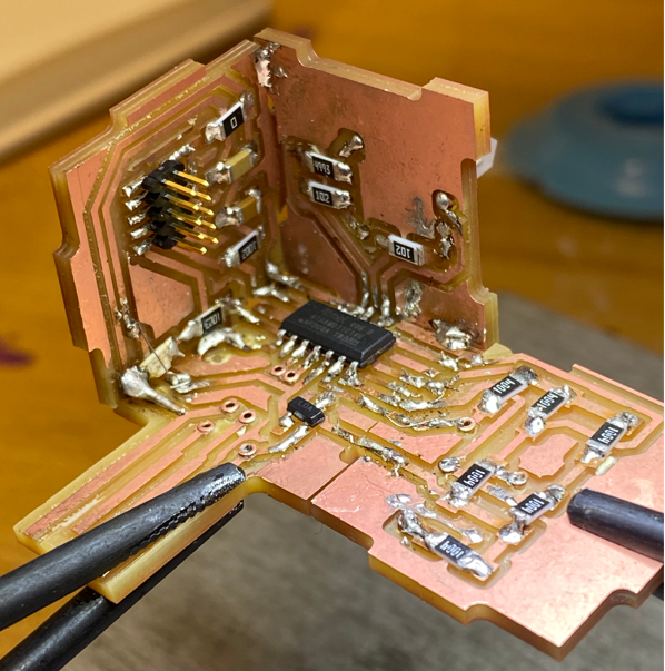
Soldering and Assembly:
Soldering the SMT components on the nicely milled size was clean, fast, and predictable.
I planned in my design to assemble the 'back' first, then the sides, which would still allow me to access the joints with the iron. I then found a potentially fatal mistake: the pieces didn't fit together well.
My 2D to 3D mental conversion skills that I've been practicing failed me. The result was that I couldn't form clean seams between face, but I was in too deep and couldn't give up.
It hit me that I could just solder small wires with some slack, fold up the side, and just mechanically tack it down to another face. To my surprise, it worked, and I had the world's ugliest (and useless) cube.
I had never bodged a board this hard, but I feel like I get a gold star for the effort. As a preventative measure, I checked connections as I soldered to make sure my bodges were working.
 Debugging and programming:
I never expect anything to work on first power-on, so I was not surprised when the useless cube v1 didn't program. Because the schematic is pretty simple,
there were only a handful of things to check: starting with the power. After probing the regulator (plugged into USB), I found that the voltage at the 5V input was around 1.3V instead.
It hit me right away what the problem was.. In the CBA shop, there are two cubbies of LM3480. One is labeled as 3.3V and one is 5V. It only became clear to me later that the voltage label
refers to the output voltage. After checking the datasheet, I found that the part I had expected >5V, so it dropped out and was not outputting 3.3V. I was able to confirm
that the ~1.3V I was seeing was the expected dropout voltage 1.2V. This was pulling the pin down even when the SWD connector (with 3.3V) was connected. This would be a medium difficulty swap because I have to replace the part in the interior of the cube, but I ran out of time
and chose instead to finish my documentation. See the untested control code below.. *cries softly*
Debugging and programming:
I never expect anything to work on first power-on, so I was not surprised when the useless cube v1 didn't program. Because the schematic is pretty simple,
there were only a handful of things to check: starting with the power. After probing the regulator (plugged into USB), I found that the voltage at the 5V input was around 1.3V instead.
It hit me right away what the problem was.. In the CBA shop, there are two cubbies of LM3480. One is labeled as 3.3V and one is 5V. It only became clear to me later that the voltage label
refers to the output voltage. After checking the datasheet, I found that the part I had expected >5V, so it dropped out and was not outputting 3.3V. I was able to confirm
that the ~1.3V I was seeing was the expected dropout voltage 1.2V. This was pulling the pin down even when the SWD connector (with 3.3V) was connected. This would be a medium difficulty swap because I have to replace the part in the interior of the cube, but I ran out of time
and chose instead to finish my documentation. See the untested control code below.. *cries softly*
