Output Devices
Speakers:
My final project will include two sets of speakers that will need to be driven at different
frequencies. The first speaker is a off-the-shelf 25W 4Ohm vibrational speaker and the second speaker is a array of ultrasonic transducers that will generate sound from ultrasound.
This week, I focused on testing the speakers, creating the boards to drive them, and writing some test code for modulation. The interesting part of this week's project is using the A4953 full-bridge motor driver
as the class-D amplifier.
Off the shelf hardware test:
This part is just for fun/demonstration, but it gives a sense of how the vibrational speaker function.
Notice how the sound quality changes based on the material and size of resonating object.
I used a cheap 18W (12V/3A) amplifier I had driving some small speakers in my room.
Design, Layout, and Assembly:
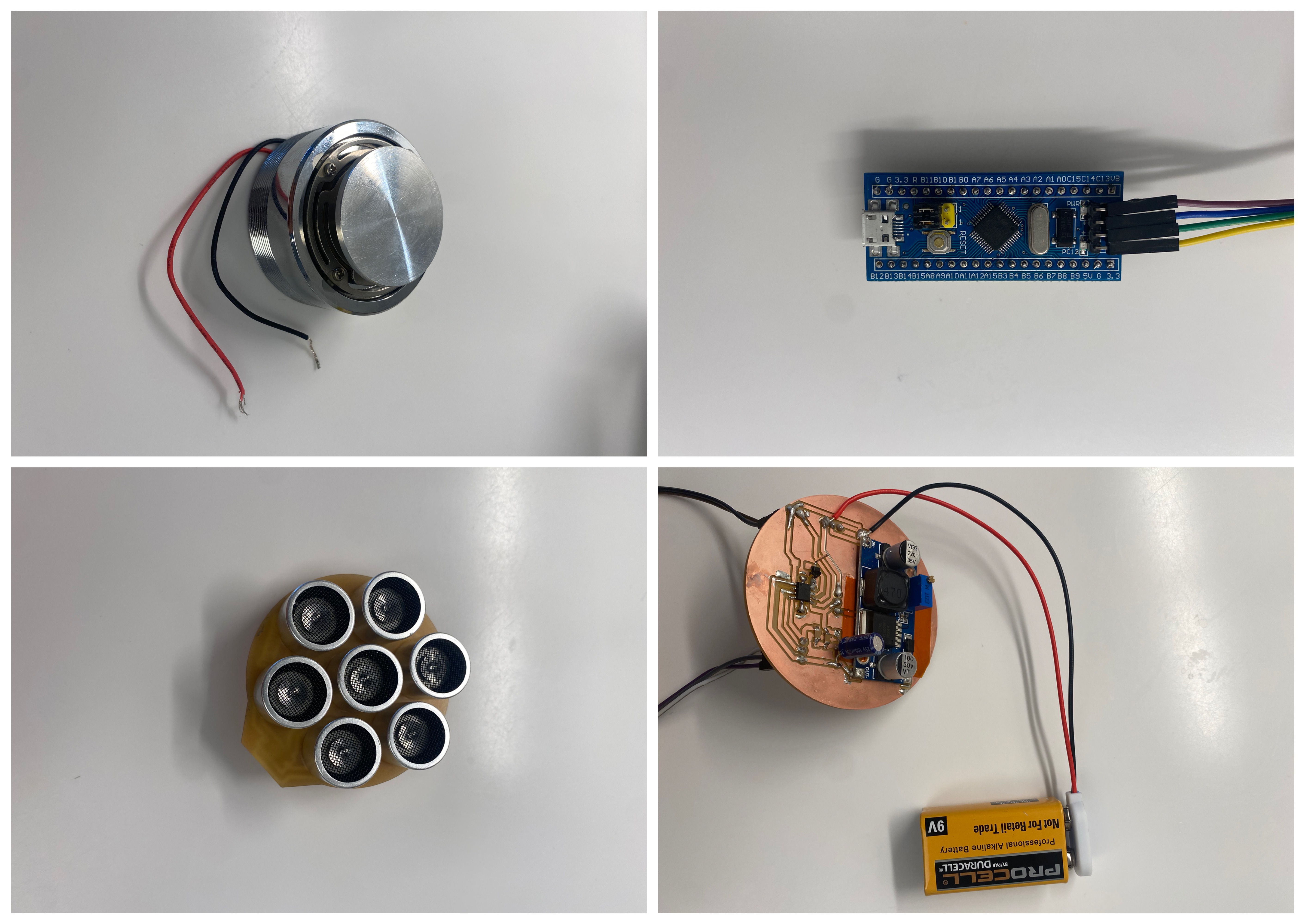
I designed two boards this week: one to hold an array of ultrasonic transducers and one to hold the power electronics and amplifier for the speaker.
The array of transducers came from a bag of TCT40 Trasmitters, which are one of the two modules on the ultrasonic distance ranging board (the other is the receiver). Turns out that if you drive them hard enough,
they can travel quite far. According to the datasheet, they're designed for 150V max.
I used the hierarchical schematic in Kicad to separate out the boards while maintaining
their connections. The ultrasonic speaker array is just 7 transducers wired in parallel with a breakout jumper. The drive board includes a output boost module
that I bought, which boosts the 9V battery input to 20V. This serves as VDD for the h-bridge amplifier,
which converts 3.3V PWM into 20V PWM signal. The output can then be low-pass filtered to form sin waves or other smoother audio signals.

Testing:
In order to generate a PWM carrier signal at 40 kHz and have the duty cycle resolution to modulate the carrier wave, I used a slightly beefier microcontroller than I had been using in this past.
This was mostly to prototype, but also because I didn't want to do this via the ESP32 module that I made a board for last week. I used a spare STM32 Blue Pill that I had lying around, which is a $3 board
with a 72MHz clock and an ARM Cortex M4 (the SAMD11/21 has a Cortex M0+). It seemed like a wise choice to prototype first and integrate later.
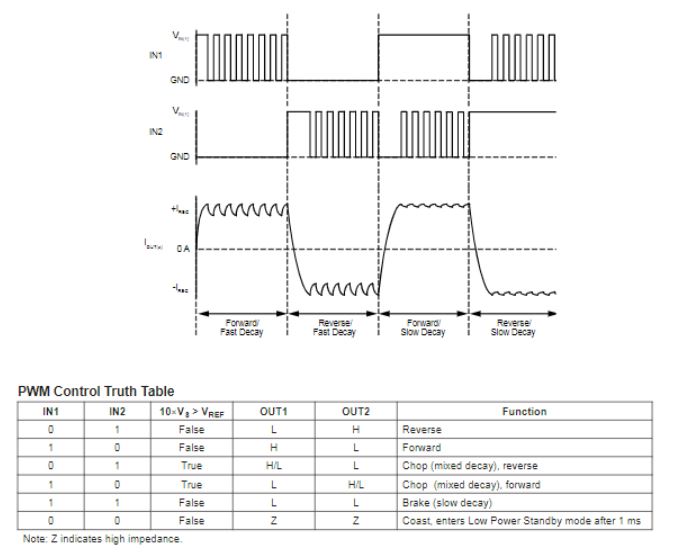
After writing the code to PWM a sin wave on a 40kHz carrier, I was ready to plug in the power. Luckily this is fairly simple because the Blue Pill has a clock distribution network with four available synchronized timers.
I also had to follow the timing diagram on the AD4953, which essentially meant I had to pull IN2 high while PWM-ing IN1. The modulated sin wave was roughly 500Hz.
 Next I tried to power the module with a 9V battery and checked the output of the boost module. There is a potentiometer that adjusts the voltage within +/-2V, so I adjusted it to a even 20V.
Finally, I plugged in the PWM inputs and measured the output. I was able to see my sin wave PWM replicated at 20Vptp with minimal distortion.
Next I tried to power the module with a 9V battery and checked the output of the boost module. There is a potentiometer that adjusts the voltage within +/-2V, so I adjusted it to a even 20V.
Finally, I plugged in the PWM inputs and measured the output. I was able to see my sin wave PWM replicated at 20Vptp with minimal distortion.
 Plugging it into my speakers, I was able to produce a fairly directional output.
Next, I tried audio streaming, but was unable to configure the ADC and interrupts properly. I ended up accidentally killing a Teensy 4.1 in a desperate attempt, but I will keep developing spiral style.
Plugging it into my speakers, I was able to produce a fairly directional output.
Next, I tried audio streaming, but was unable to configure the ADC and interrupts properly. I ended up accidentally killing a Teensy 4.1 in a desperate attempt, but I will keep developing spiral style.