final project ideas.
Click here to learn more about my original final project idea. Realized very early on that this project was way too hard for me, but its always fun to have big goals! Hope to make it someday. :)
final project work.
My new, revised, and more reasonable idea is that I want to make a device that will turn on and off a light switch when I clap. Even though this seems pretty simple, it was actually quite a challenge for me and I learned a lot. Also thanks to Anthony for being so patient with me. I truly must have been the student who tested his patience the most. Thanks to the many hours of electronic help/debugging!
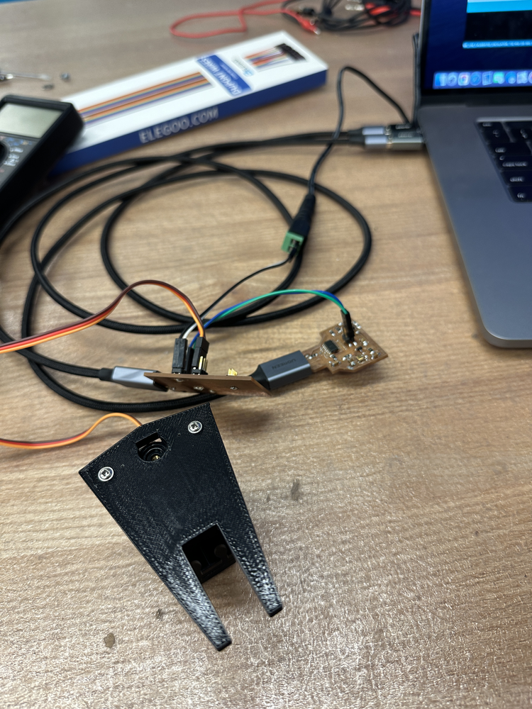
Due to Neil (and Zach's) good advice, luckily I had been working on weekly projects that would be helpful towards my final project. Therefore, I mostly just had to package and assemble my final project. The board I had made during the "input devices" week had a microphone and the board I made during the "output devices" week had the potential to move a servo. Therefore, I now needed to make a device that would attach to the servo and turn the light switch on (I also ordered a light switch off of Amazon).
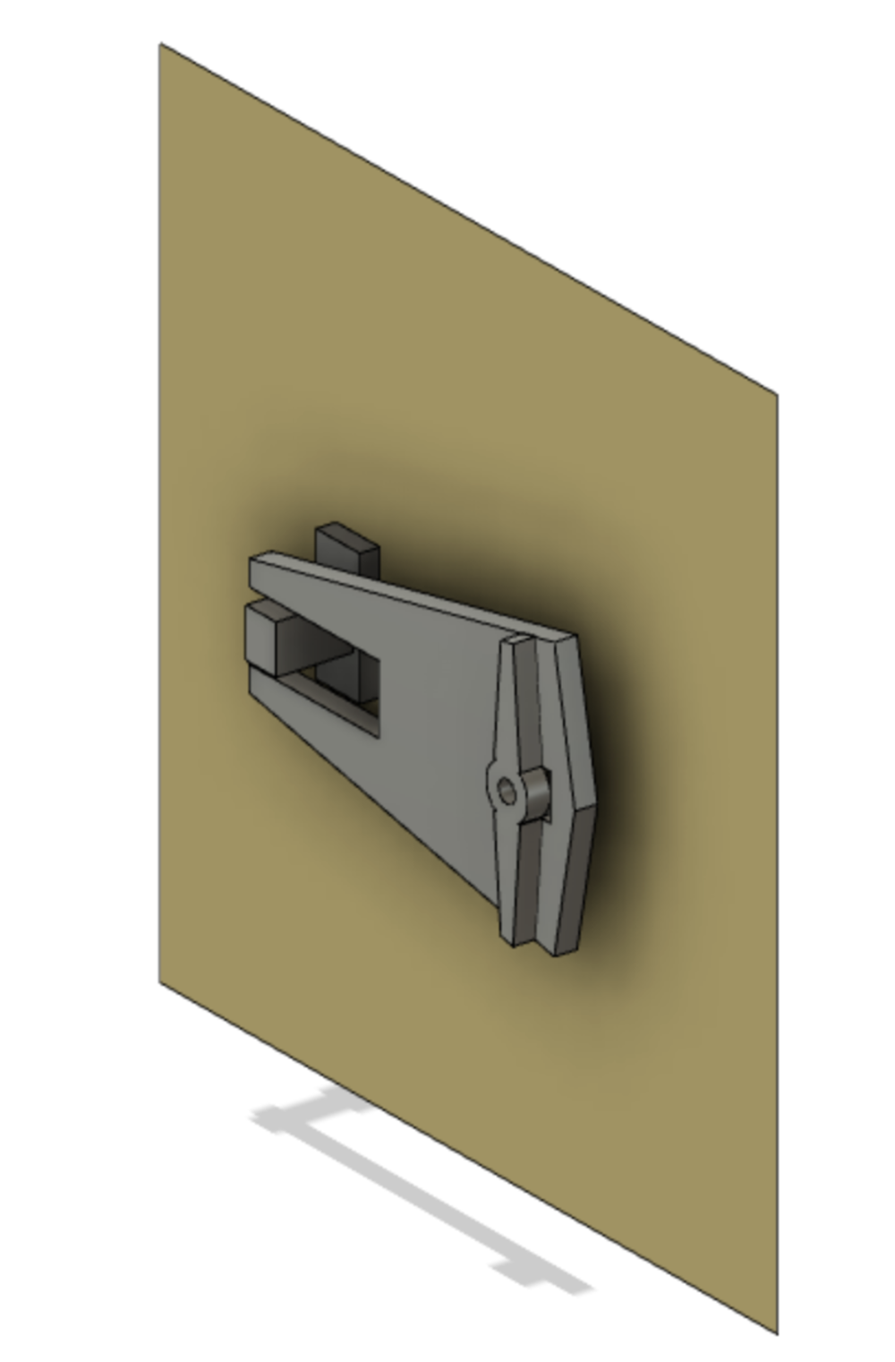
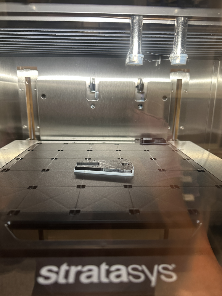
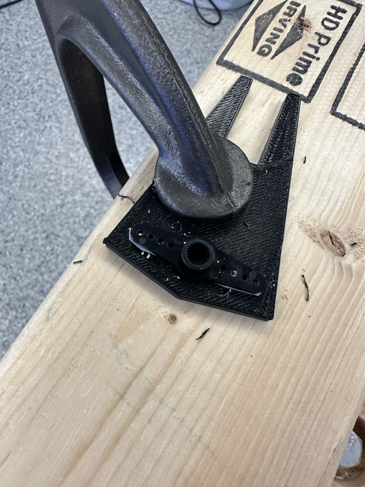
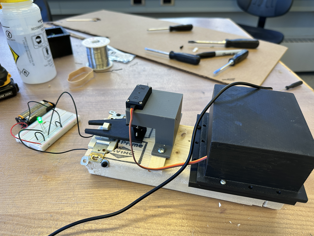
With some help from Alfonso on how to effectively make a toggle, I designed one in Fusion. I was quite rusty since I hadn't worked with Fusion in months, but with Alfonso's help I got it done. Then I printed it out on the very cool stratasys F120 at EDS. Everyone was being so nonchalant about the machine, but I thought it looked hella cool. Then I drilled small holes in the plastic (marking where the screw holes should be), and then finally threaded screws through, which secured the part to the servo motor.
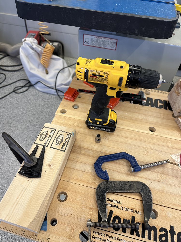
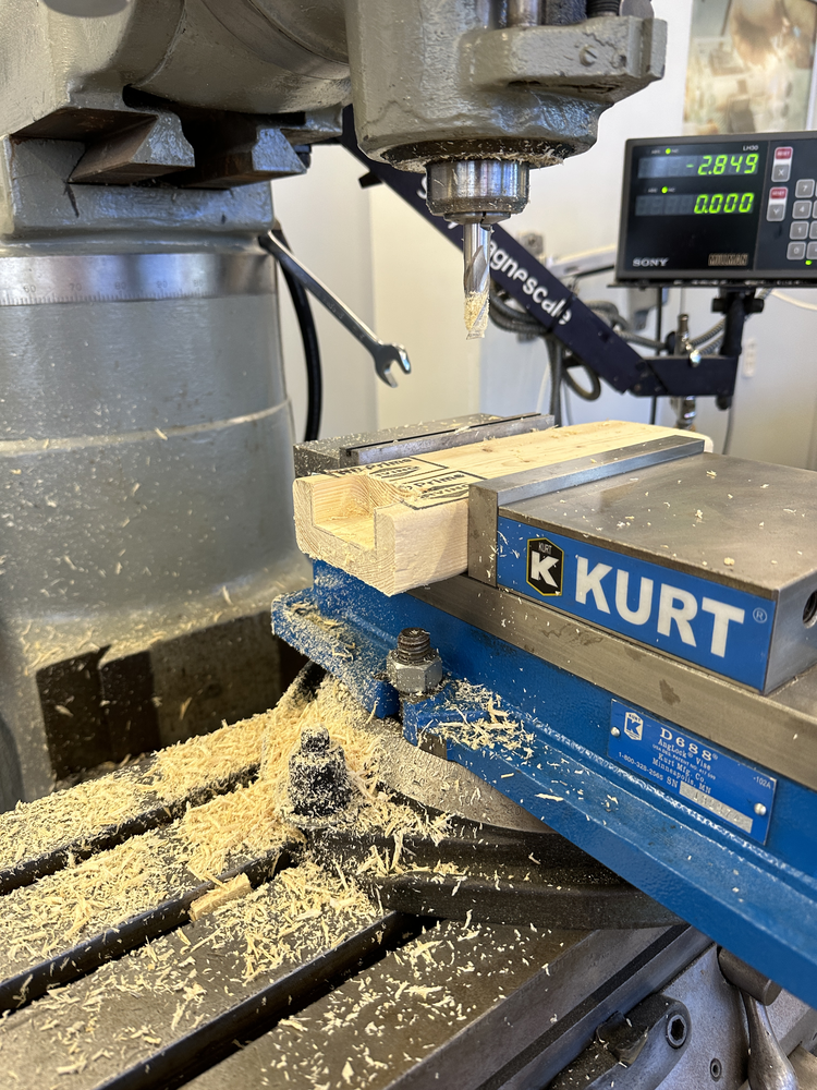
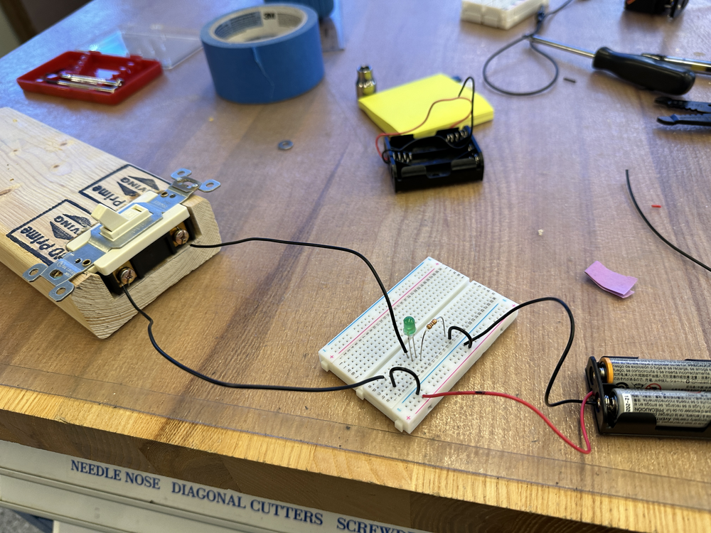
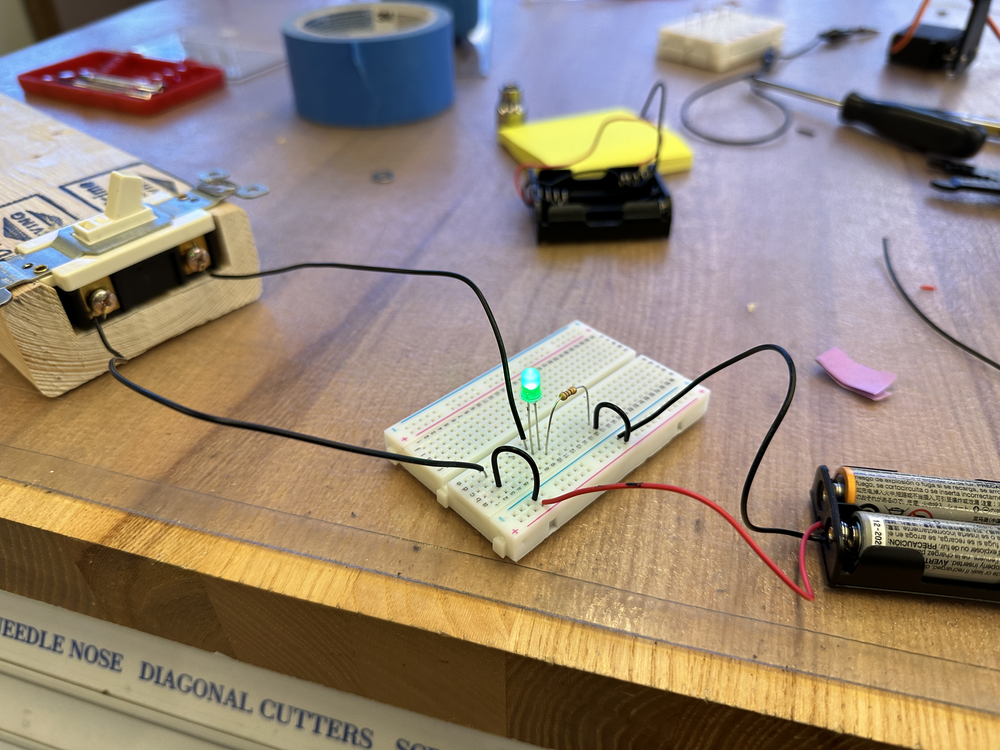
Then I needed to actually mount the light switch. With Dave's help, I used the milling machine at EDS to make a slot for my light switch. Then I also wired up the light switch to an LED using some some jumper cambles and a breadboard. This was pretty interesting because I had to remember some basic things about circuit making and using Ohm's law to calculate what resistor I would need. By now, I basically had everything that I would need. I just needed a "holder" that would hold the servo in place. Then I was done!
I made the "holder" in Fusion as well by using calipers to be very careful with my measurements. Then I 3D printed (but this time not with the stratasys :( ) it, a process that look 3 hr and 24 min.
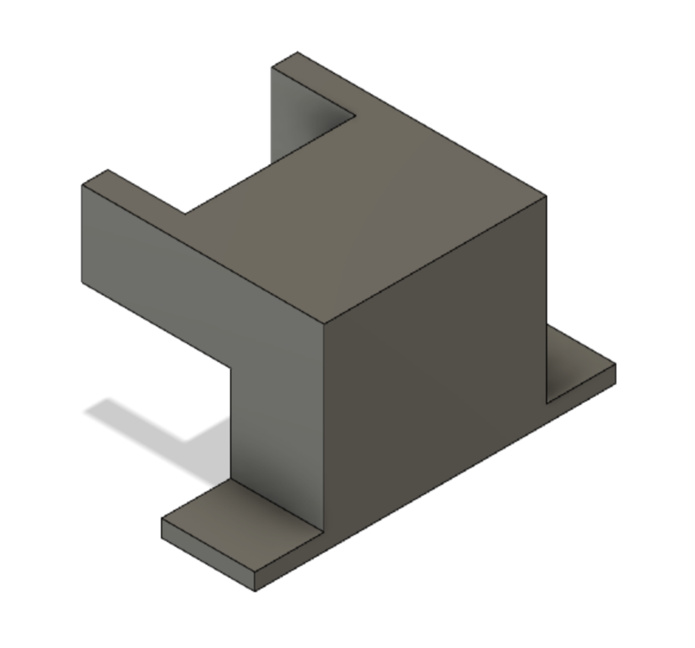
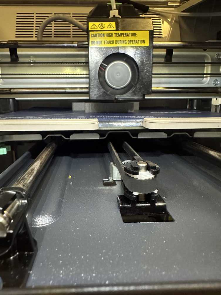
I first attached the servo to the holder by drilling pilot holes and then carefully screwing in. Then I needed to attach the holder to my piece of wood which had my light switch bolted to it. In order to do that, I needed to cleverly use some clamps (and Alec's help) in order to get everything perfectly aligned. I also put a small piece wood underneath the holder in order to raise it a bit. Then I just drilled some screws into the plastic and wood to hold everything together. Finally, I wired everything up and uploaded the correct code.
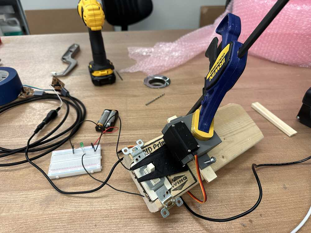
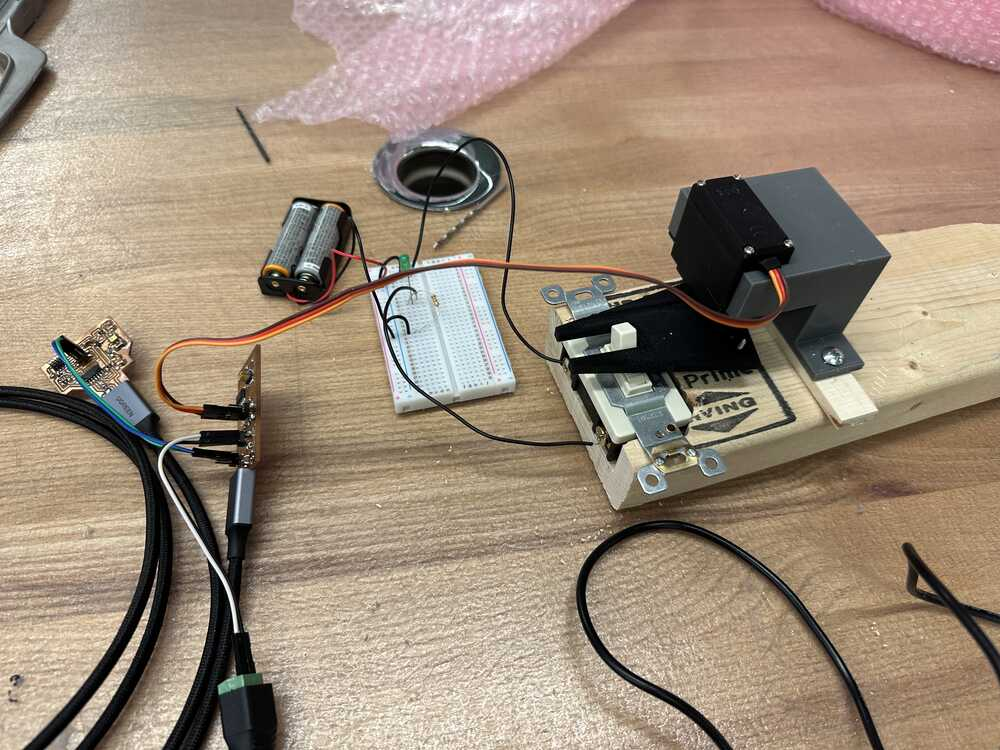
It was time to test and I was very nervous. However, somehow everything worked perfectly the first time! Here is a video of everything working:
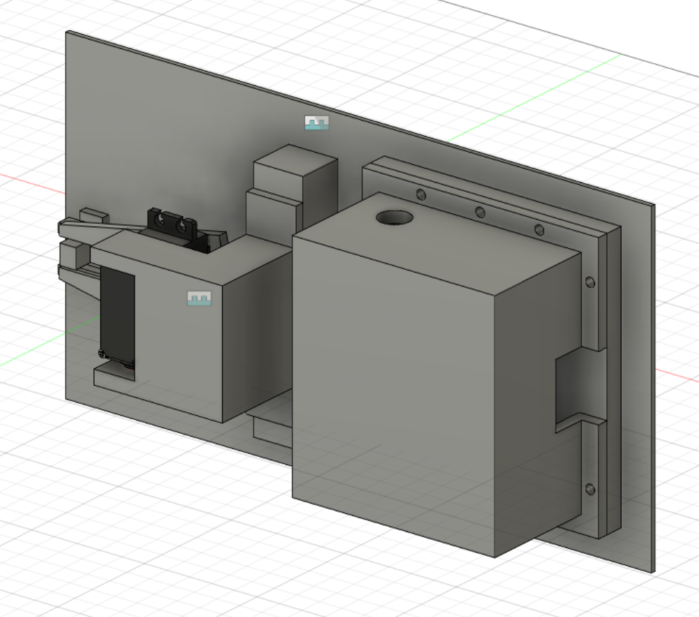
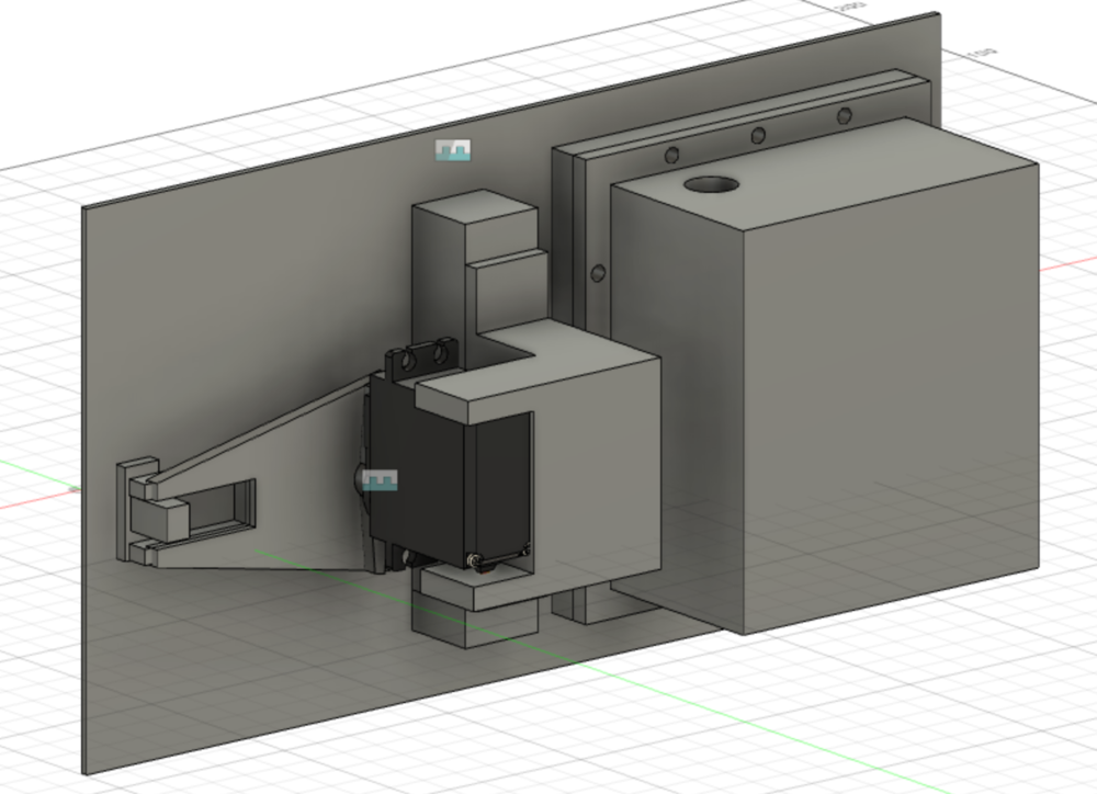
Finally, I needed to package my tangle of wires very neatly. Therefore, I designed a container for my boards that had holes in order for wires to pass through. Here is that design (front and back):


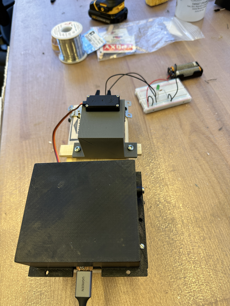
Lastly, I put everything together: first I 3D printed my design, carefully aligned it into place, and then screwed it in. It looks really nice (only the wires needed for power stick out on one end)!
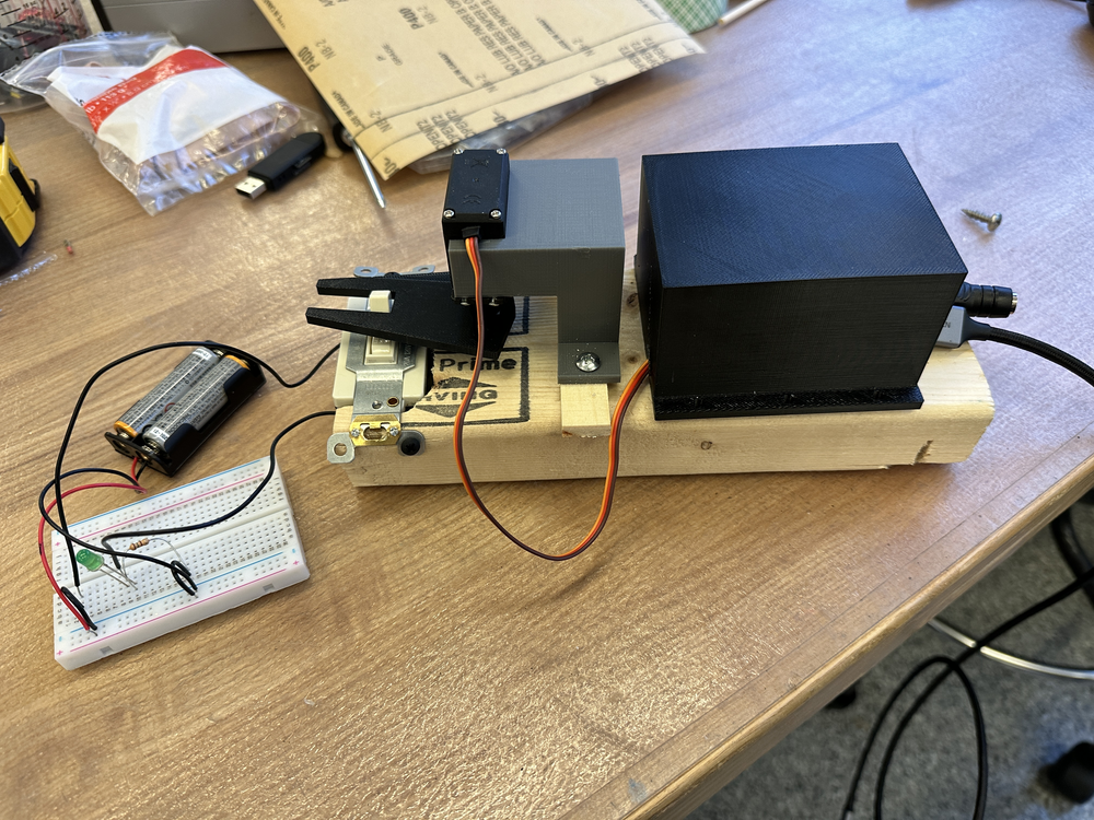
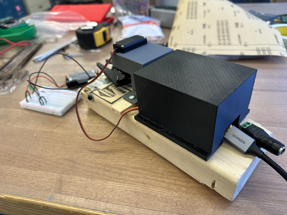
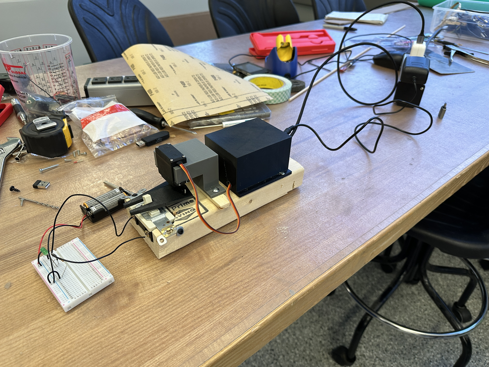
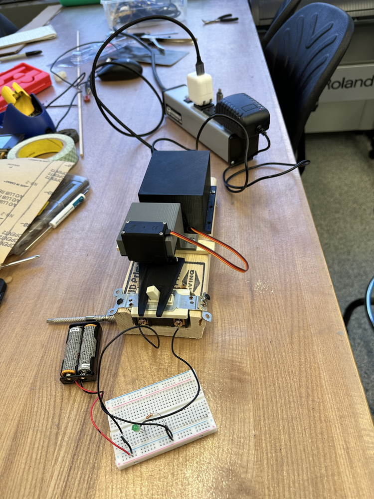
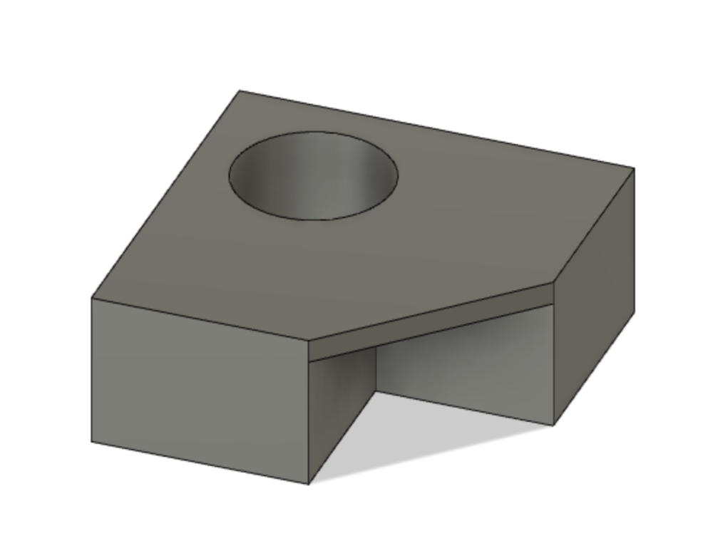
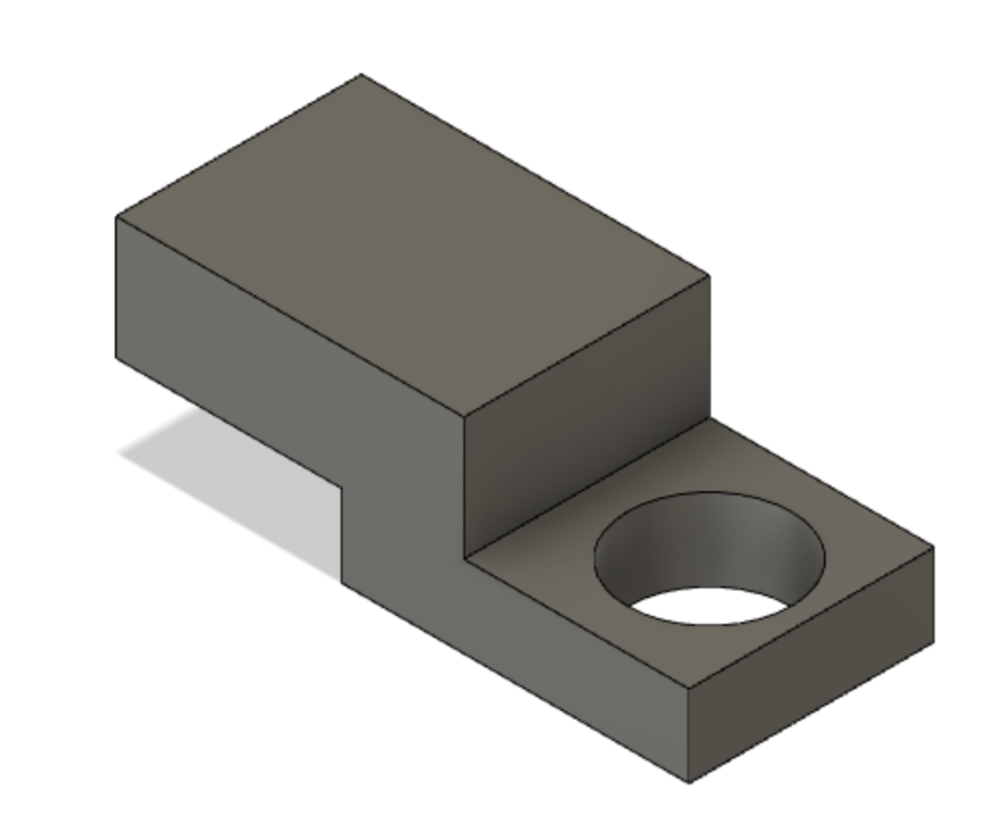
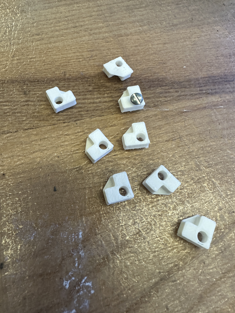
However, in order to completely integrate the packaging, I took some additional steps. First, I designed some tabs in order to bolt my PCB boards down to the piece of wood. This would allow them to not move around. Making these tabs was surprisingly hard and took 3 iterations. Since the tabs were so small, sometimes the 3D printer would not print them properly, then meaning that the screw hole would not be big enough. Also I ran into a slight issue when one of the boards was too long to fit two corner tabs and fit under the black bow I had made, so I had to design one special "side tab" for that board.
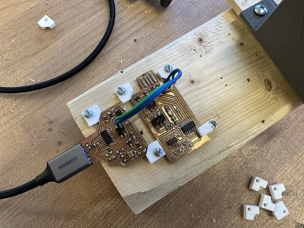
Additionally, I used a Dremel to bore a hole in the side of the black box I had made in order to feed the power cable through it. This was my first time using a Dremel, and it was definitely more tricky to use than Anthony made it out to be! Then I used some 5 minute epoxy to secure the cable into place. This made everything look super nice and clean (even though I didn't apply the epoxy particularly well)!
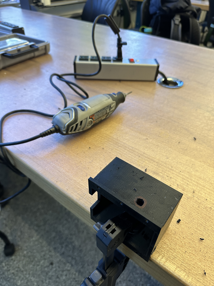
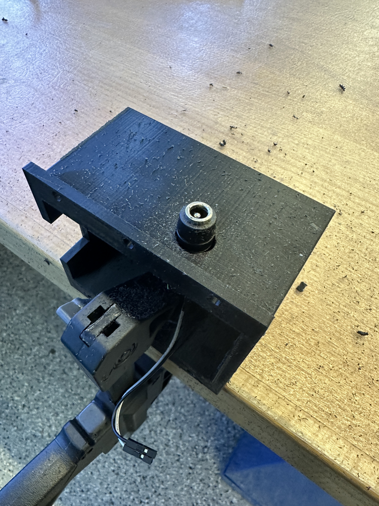
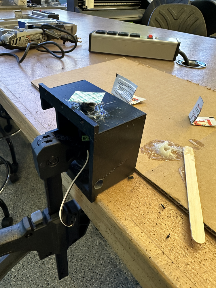
Then I was finally ready to hook everything back up and put the black cover back on. I'm very glad I made these changes to the packaging; it makes everything look so much nicer!
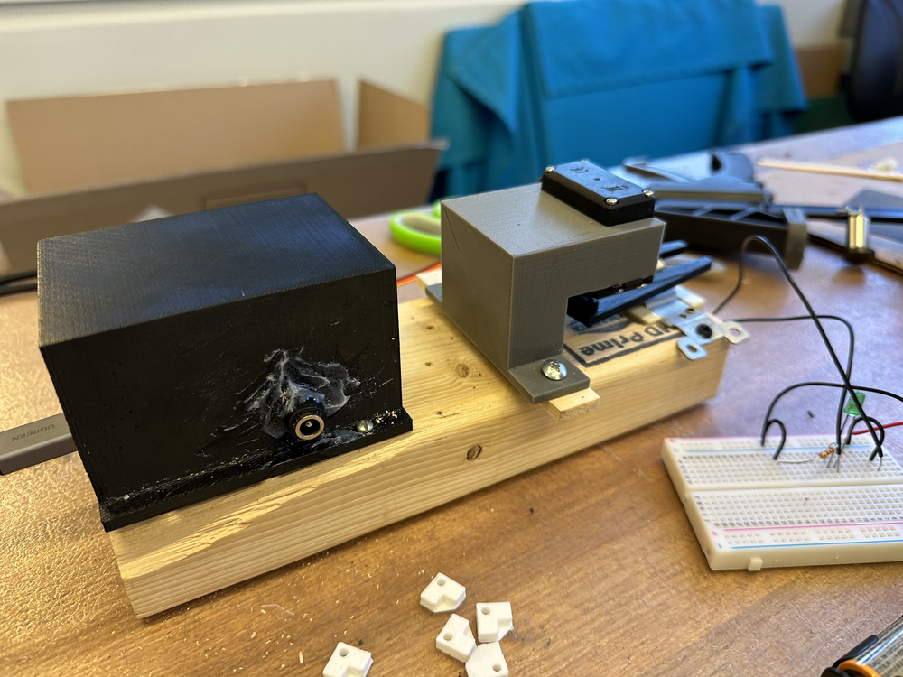
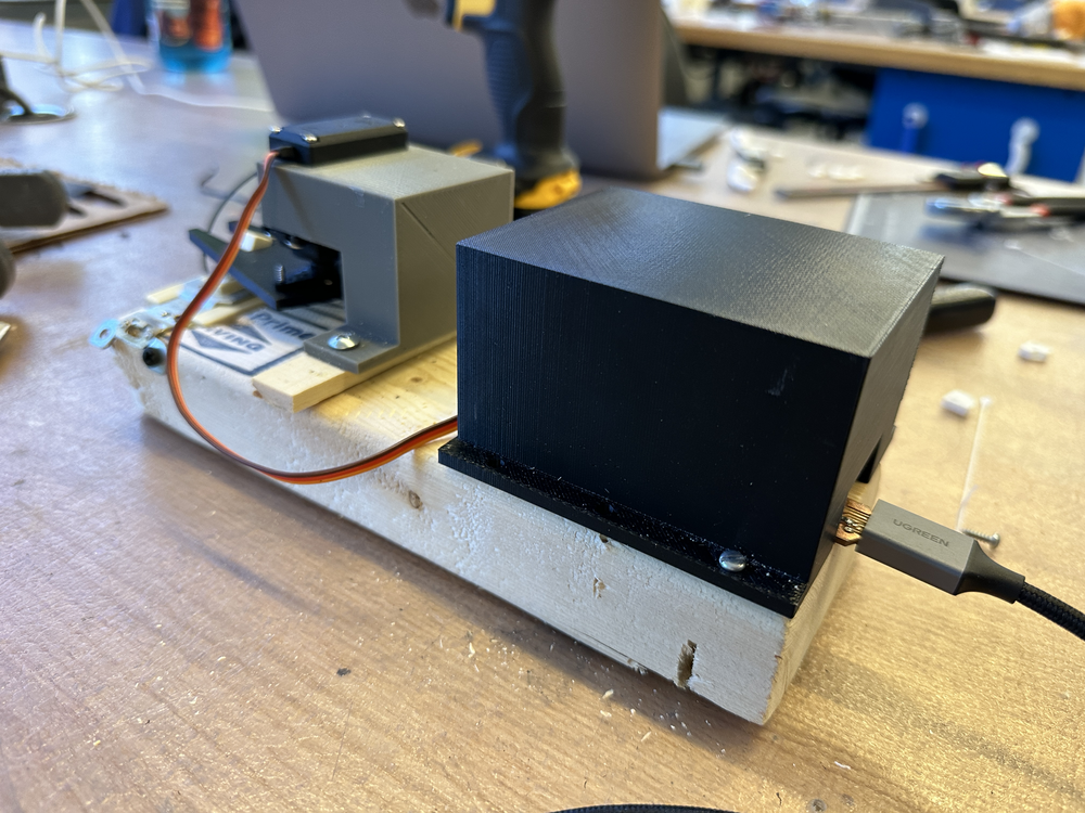

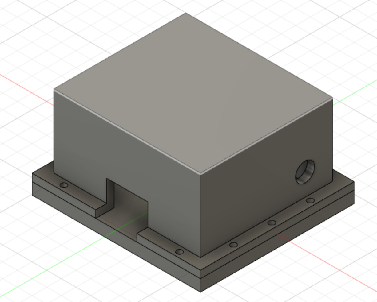
However, I then realized that the boards were screwed to the wood, which I was modeling as the wall. This was not realistic as no one would ever screw boards into their wall. Instead, they would like to just mount one thing. Therefore, I decided to design another capsule for my boards, but this time one that had a covering on the bottom. This was not too hard to CAD since I just slightly modified my previous design. In particular, I made it a little bigger so my boards could fit comfortably and also widened up the wire holes since last time I had to resort to some sanding in order to fit the wires. I also added holes for the nails I would eventually use to secure the box to the wood and also the box together. After I printed the new capsule, I soaked it in the citric acid solution for around 2 days to remove all rafts. I was finally ready to assemble again!
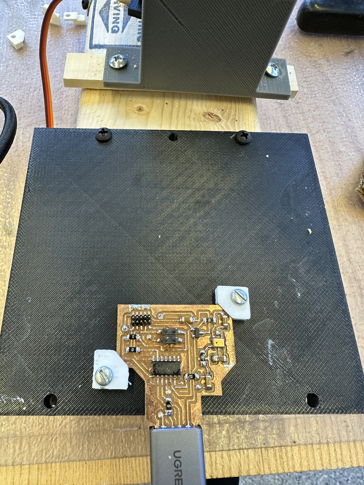
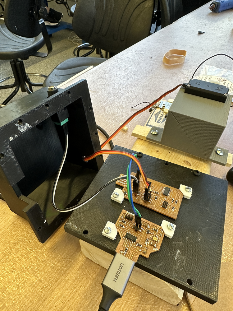
First I epoxy-ed on another plug. This time I decided to epoxy from the inside for a much cleaner look. Then I unscrewed my previously secured boards and resecured them to the new base I had made. Then I fed the correct wires through the holes and secured the top of the box. I was happy to see that all wires fit properly now. Lastly, I screwed on the top of the box. I did all the screweing by first selecting an appropriate sized drill bit and then drilling pilot holes. Then I hand screwed the screws into place. I was finally done!

Lastly, here is a CAD of the whole thing. I did everything myself except downloading CAD for the servo motor from the Internet.
Finally, here are the final presentation questions answered:
- What does it do? When you clap, it turns a light on and off (one per clap).
- Who's done what beforehand? I'm sure similar apparatuses have been made before, but I'm unsure if anything has been done with my design.
- What did you design? I designed an apparatus (electronics, servo, and a holder) in order to turn a light switch on and off when one claps.
- What materials and components were used? I used a block of wood, PCB boards that I designed, milled, and soldered, a servo, 3D printed parts, and a light switch.
- Where did they come from? I purchased the light switch and made everything else myself.
- How much did they cost? The light switch cost $10.
- What parts and systems were made? I made a servo board, a micorphone board, and two 3D printed two parts to attach to my servo motor.
- What processes were used? I used a mill to make my PCB boards and a 3D printer to print parts.
- What questions were answered? I learned about what electronics are needed in order to get a servo motor to run and a microphone to work.
- What worked? What didn't? Few things seldom worked the first time. The eletronics was especially hard to deal with as I have documented in my weekly summaries. Surprisingly, the 3D printed parts all succeeded the first time.
- How was it evaluated? When I clap, the light turns on and off!
- What are the implications? I now have a lazy way of turning my light on and off from bed. :P
Finally, here are the files: Claw STL Holder STL Housing STL Corner Tab STL Side Tab STL Top Housing STL Bottom Housing STL Full CAD Model