embedded programming.
If we recall, I had ended week 4 with not even being able to get my board milled due to a series of misfortunes. The last issue I had encountered 2 weeks ago was that while the vias were drilling, my board would lift and drill itself through. Therefore, with the help of Justin (who knew Photoshop), I split the outline png into two: a png with just the vias and a png with just the outline. My friend Chad (from outside the class) wanted to see a pcb mill, so I invited him to watch as I milled. I think the pressure to perform in front of him caused me to work much more carefully, and somehow I milled the board correctly the first time around. Somehow, nothing went wrong and the traces came out perfectly. In fact, I might as go as far as to say that it was the nicest board I have ever milled. So yay, I finally had a board!
So I quickly got to work soldering all the correct parts onto my board, taking precaution to orient all the parts in the correct directions. However, when I got to the voltage regulator, I realized I had designed the pcb using the wrong 3.3V regulator (I used the one with 1 amp). However, Manu said that it might still work and it was the last piece I needed to solder on, so I decided that I might as well just solder it on. Finally, I was ready for programming! (Or at least I thought so.)
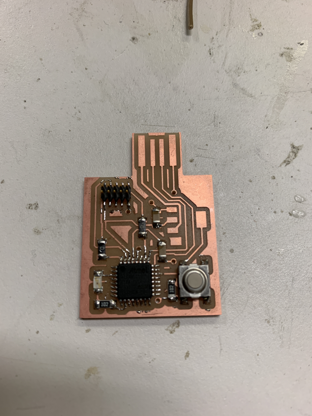
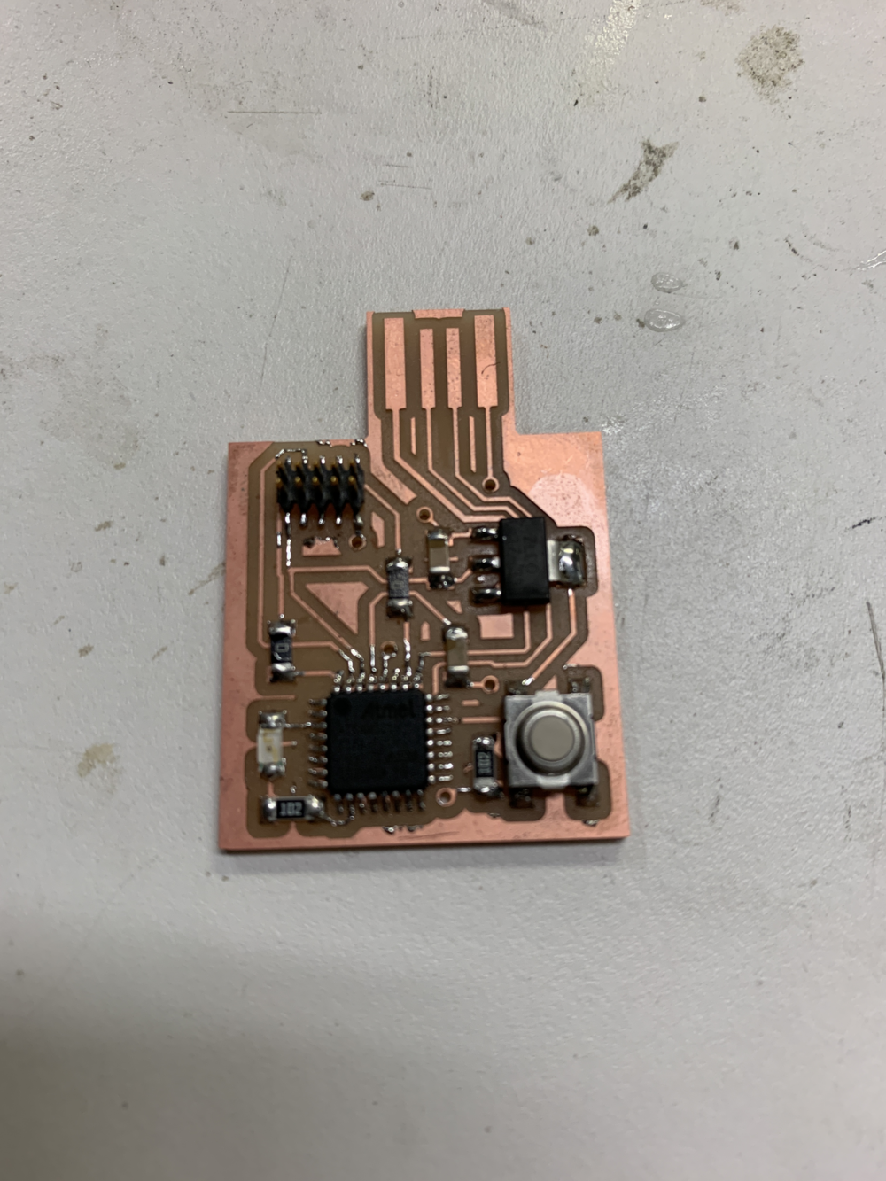
Manu was kind enough to help me with programming. If you recall, she also helped me install edbg on my computer two weeks ago. I also asked her to quickly inspect my board before I start programming, and she has such good eyes! Somehow she caught a huge mistake, which was amazing. The JTAG is supposed to have 3 grounds, but I had only connected 1 to ground. Therefore, Manu suggested the hack-y idea of just adding a solder bridge to fix the mistake. I was ready to try anything at this point, so I took her suggestion and added an ugly solder glob to my very nicely soldered board. Finally, I plugged my board into the USB port of my computer dongle, the debugger into the 2x5 header, and the other end into another USB port on my computer. Then with Manu's help, I downloaded the SAMD21E18A bootloader from Jake's website. Then using EDBG, I tried to flash the bootloader onto my board. However, I got an 'invalid response' error. I tried reversing the JTAG connection, but the same error persisted. It was all very confusing since the green light was on the debugger, indicating that the board was connected. Manu suggested that it might be some hardware issue, which was very disheartening cause this basically meant I would need to start again.
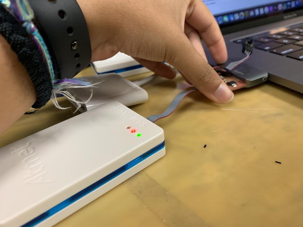
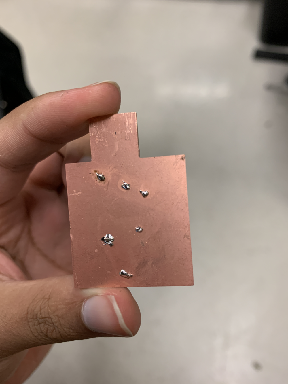
However, just at this time Jason walked in. I told him what was up, and he immediately mentioned that I hadn't taken care of my vias! He taught me how to put rivets into the via, hammer them in, and then solder on connections. I had 6 vias so I treated all of them as he taught. It was actually super fun to hammer the rivets in and add solder globs onto the back of the board. Then Jason told me about Microchip Studio, which was super helpful. I selected the correct board and checked the reading. In the first JTAG orientation, I got a reading of 2.7V, which was concerning. But when I flipped it around, I got the perfect 3.3V reading! I was ecstatic. Jason then showed me how to flash the bootloader onto the board from within Microchip Studio and it was so simple. Thanks Jason! So I left that night feeling pretty content that I had the bootloader on my board and all I had to do was program it.
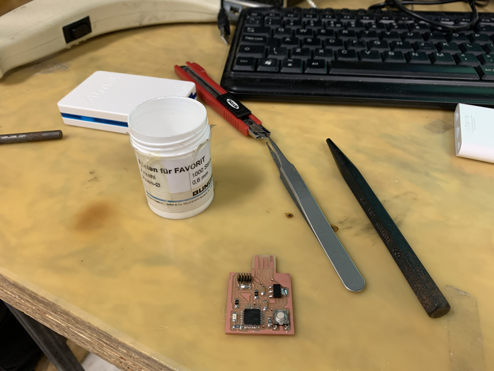

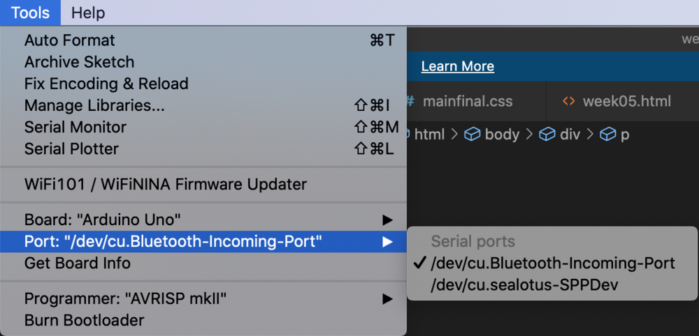
So onto programming. I once again followed Jake's instructions from here to set up Arduino correctly. However, I could not see my board in the 'Ports' menu. I decided to ignore that issue temporarily and quickly write up the programming. Taking inspiration from this FabAcademy project, I wrote my code (essentially slightly modified the code found on the website to match the pins on my board, which I read from Jake's website/the SAMD21E18A datasheet.) I compiled the code, and it compiled properly. However, as expected the upload did not work since my board was not recognized. I spent an hour or so trying to debug, to no avail. I hope to come back to this in the next couple of days.

Update! I resumed working on this board on August 3, 2022. I still needed to make a lot of boards, and I thought it would be a good idea to be able to get at least one simple board properly working before attempting to make more complicated boards (which I would need to make in order to finish the other weeks' assignments and also the final project). I should also note here that I have now switched to working at EECS's EDS (Cypress Engineering Design Studio) and am not working out of CBA anymore. This is because I required a lot of help, and Anthony (Pennes), the EECS section's technical instructor, graciously offered to help.
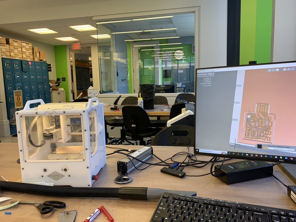
The first day I showed up to work on my PCB boards, I told Anthony about all the issues I had with milling this board. I thought I was just having milling and soldering issues, but Anthony immediately noticed that my schematic had an issue. I had accidentally switched the pins that CLK and DIO were to be on. Therefore, even if I had perfectly made my board and soldered on the pieces many months ago, it would have never worked :(. I quickly fixed that mistake and then re-routed that part of my board. I was set to mill! I was very happy to learn that EDS has a Roland mill as well as the Other mill. The Other mill is so amazing and has definitely made my life much easier. First of all, it is AMAZING that you can just send it .brd files and it just mills the board. Using mods with the Roland would literally give me so much anxiety since so many things can go wrong as there seems to be so many settings. Also all the issues I cam across with the Roland are documented above. To my complete shock, the Other mill perfectly milled my board the first time around. Simply amazing.
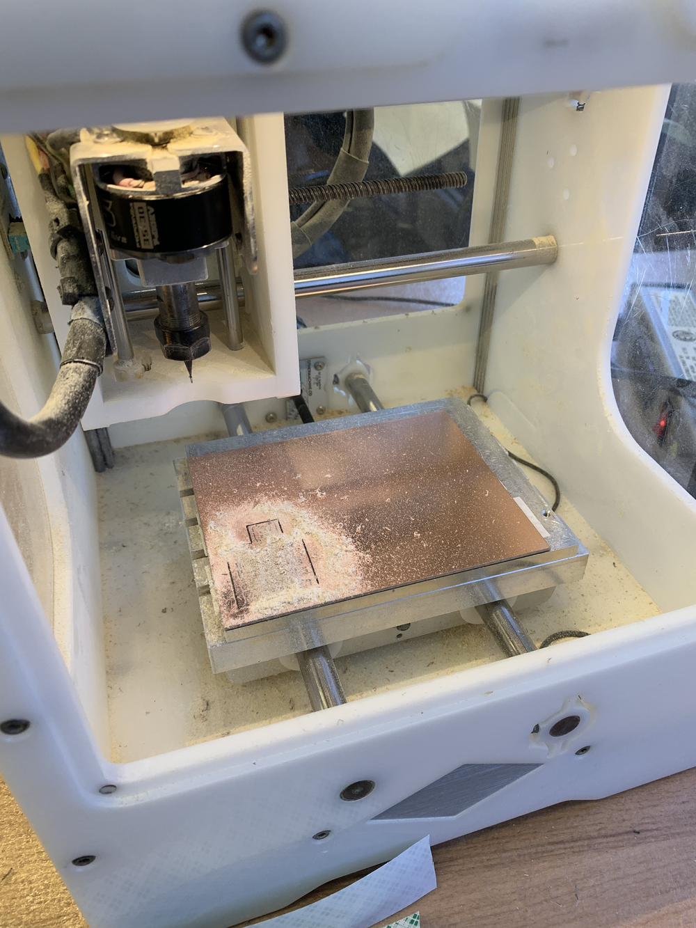
I finally started soldering and this part went pretty smoothly after Anthony gave me a crash course on how to solder. I'd honestly forgotten about a lot of the tricks I had discovered for myself so it was actually trickier than I remembered. Additionally, I had forgotten about the existence of flux, but when I did remember, it was a GAME CHANGER. But as I would soon learn, my soldering was not as good as I thought it was. After finishing soldering, I attempted to flash my board with a bootloader using the Atmel ICE. Recall that this is basically as far as I had ever gotten during the class. However, as my luck would have it, when I plugged my board in and attached it to the Atmel ICE, the Atmel ICE displayed that only it had power and the board did not. This is when I realized how bad my soldering was.
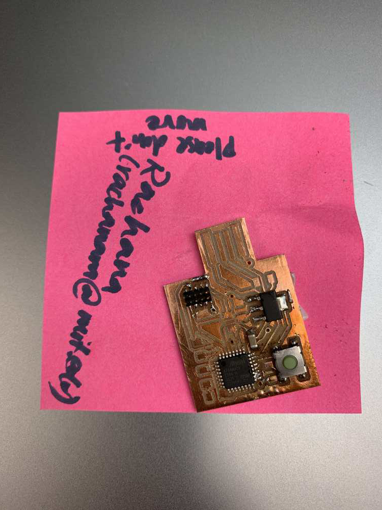
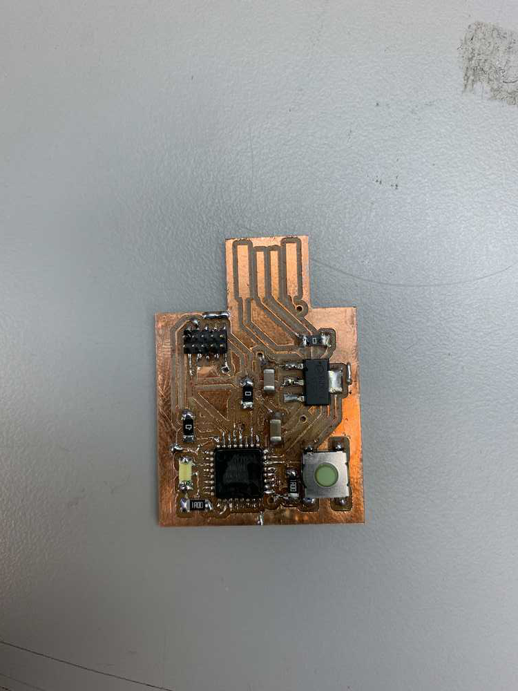
What commenced next was hours of Anthony pointing out that I had bridging somewhere and then me going and then fixing it. However, even after all of that, the Atmel ICE displayed that my board had no power. Therefore, Anthony hypothesized that my regulator might have been fried. Therefore, he told me to use the hot air gun to heat the part, lift it, and replace it. But of course dumb me decided to not listen to Anthony and just attempt to lift the part using the soldering iron (since I thought it would be faster and easier and I was tired). I soon paid for this mistake. As I attempted to heat up all three legs of the regulator at once and pry it up, I ripped up one of my traces. I was devastated as I thought I would have to re-mill my board and start from scratch. However, Anthony suggested a "hack" to fix my problem. He suggested that I just run a wire between the leg of my regulator and the trace it needed to connect to. However while attempting to do that, I melted off that trace as well. Thankfully Anthony came in a saved the day with his magical soldering skills and managed to bridge that gap with the same wire as well (this is the gold wire in the picture). Finally my regulator was properly replaced. However, the Atmel ICE still displayed that my board had no power!
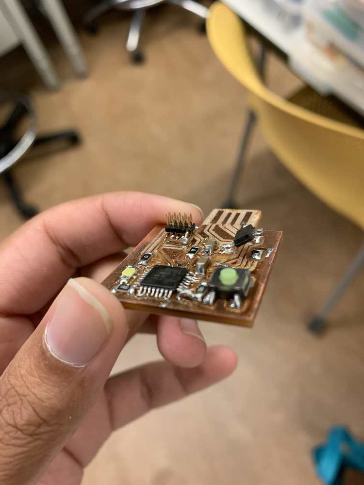
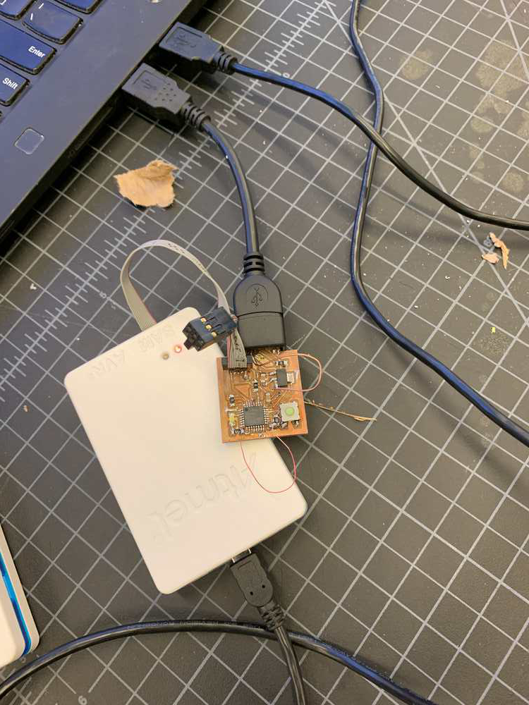
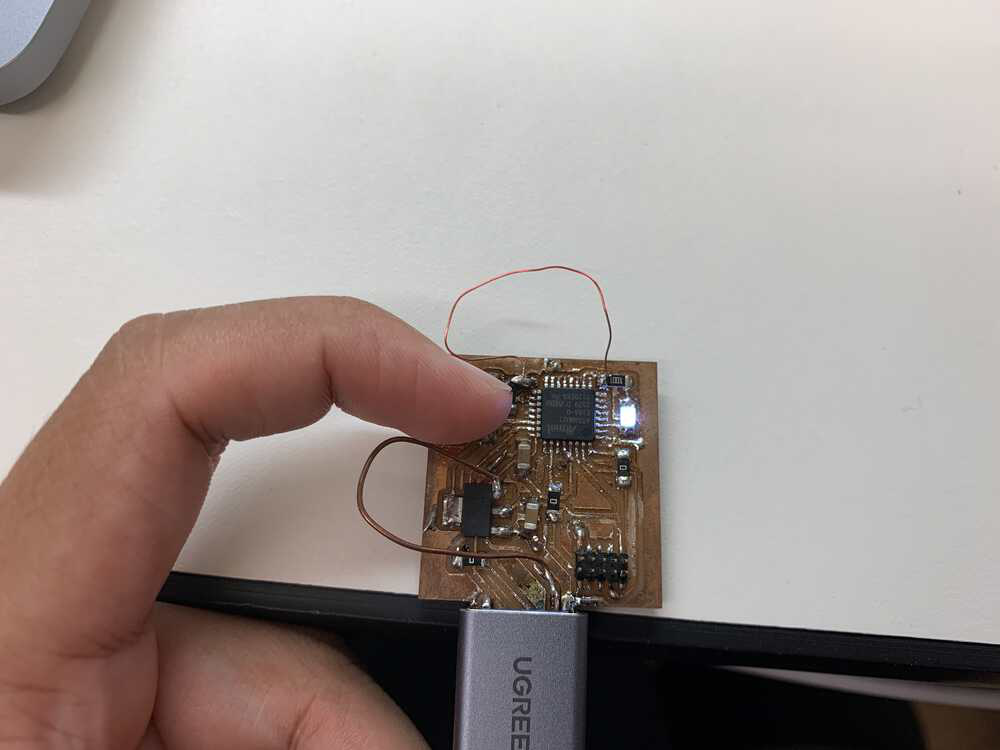
Therefore, Anthony said that the last resort was I should replace the SAMD21E microcontroller, as it could have shorted. Thankfully, this time I listened to him and actually used the hot air gun, which was a quick and easy process. However, the board still did not work. Then Anthony noticed that the VDDCORE was not outputting 1.2V as desired. (Note that the SAMD21 has multiple power pins, and VDDCORE is one of them. That datasheet describes it as VDDCORE: Internal regulated voltage output. Powers the core, memories, peripherals, FDPLL96M, and DFLL48M. Voltage is 1.2V.) This turned out to be an issue with the trace going below the SAMD21 which was causing the chip to not be grounded (very bad!) Instead of lifting the chip up (again), Anthony instead had me solder a wire from the chip to ground. When I lifted the microcontroller previously, I remember thinking that the GND trace looked corroded. But it did not occur to me that the corrosion could be the issue, which is very stupid in retrospect. Finally after fixing the issue, the Atmel ICE displayed that my board had power! I succesfully burned the bootloader on using Arduino (not edbg) and I was finally ready to program. I wrote some very simple code to turn the LED on when the button was pressed and it worked! Yay, finally had made a working board, even though it was kind of jank.
Here are some simple hardware debugging tips I learned from Anthony:
- If you are not reading 5V and 3.3V in the correct spots, then see if ground is connected to ground everywhere and 5V is connected to 3.3V regulator properly.
- If you are not reading the device signature on your computer (microchip studio for Windows or lsusb for Mac), you should check the data channel connections, which are DIO, CLK, and RST. There might be some issue in the connections there. In my case, there was an issue with the JTAG connector RST pin was not soldered all the way down (not making connection).
Now when I was about to start adding pictures to this post, I realized that I had forgotten the ImageMagick commands to compress pictures and I could not find the webpage on Neil's site for the life of me. However, I have found it now (thanks to Anthony's help again), and it is here. In case that link stops working, the relevant commands are
- convert PNG to JPG: convert input.png output.jpg
- convert all PNGs to JPGs: mogrify -format jpg *.png
- compress JPG to quality 50% width 1000: convert input.jpg -quality 50% -resize 1000 output.jpg
- compress all JPGs to quality 50% width 1000: mogrify -quality 50% -resize 1000 *.jpg
Finally, here are the working files: Schematic PCB Arduino Code