input devices.
Note: this work was done starting August 2022.
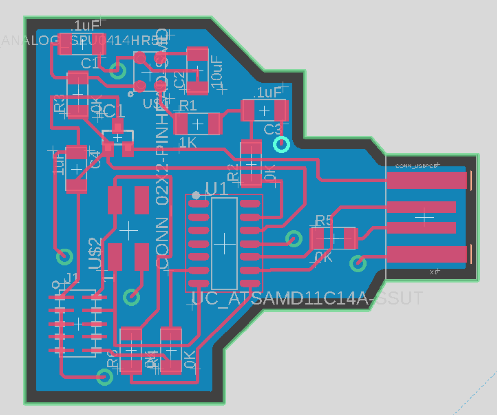
This week, I wanted to create a board with a microphone on it so that I could use it for my final project. Since I was hoping to connect this board to another one for the sake of my final project, I included a 2x2 header on the board and connected those pins appropriately to the tx and rx pins on my microcontroller. (More about this in Week 10.) I luckily had already made the schematic for this board back in December 2021 with the generous help of Zach, so all I had to do now was route. One quick note about the schematic though. When I opened it up again in August 2020, I was very confused about why I had random capacitors of random values in my schematic. I learned about how a microphone works from Anthony and why the capacitors are needed. However, what I wanted to highlight here is that a datasheet should be consulted to determine what value capacitor or resistor to use! I used to think these values were pulled out of nowhere, but turns out that they are simple calculations given in the GOD sheet, aka the data sheet.
I learned many useful tips from Anthony involving routing.
- Pressing "slash" activates the command line mode, which is so useful to quickly switch between tools. (Since you can just type the tool name into the command line.)
- Press "r" to go into routing mode very quickly.
- Use a trace width of 12 and a via diameter of 40. (Enter these values into the routing menu that pops up when you press "r.") Optionally, make the trace coming from 5V have a trace width of 16.
- Use "esc" to quit any mode or tool you are in.
- As you start routing, you will notice this incredibly annoying thing where the traces want to "snap to this weird grid." In order to have more precise control over where traces are lying, press "option" as you move your traces around.
- Use the command "drc"! (This stands for "design rule check".) This command allows you to think that there is enough room for the mill to make your board. If you do this, make sure to go into "clearance" in the drc menu and change all the top values to 16 mil (under Different Signals).
- Feel free to use jumper 0 ohm resistors! They are your best friend.
- First you want to use the polygon tool to create a polygon that covers your whole board and label it "GND".
- Then you want to delete the "boundaries" of the gray workspace you are working on.
- Finally use the "board" tool to outline your board. Make sure to follow the given markings near the USB, but otherwise you can create your outline however you want.
- If everything worked properly, then all the background should have disappeared and you should only be left with your PCB!
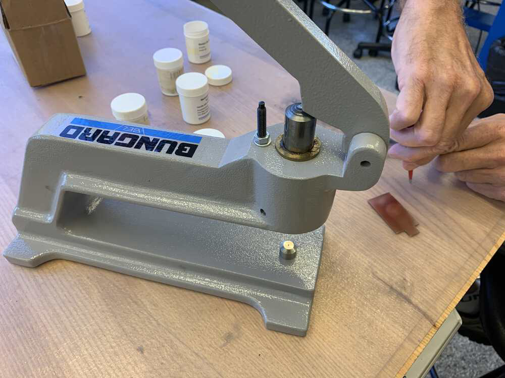
After completeing routing my board, I milled it and soldered the correct parts on. I used the fancy rivet press that Dave (another technical instructor at EDS) hides in his office due to it being easily damaged, so I felt very lucky. Also I "invented" a new technique around now which I use to strip the copper around the USB. I include it here in case it is useful for anyone. So basically a secret is that I am kind of scared of utility knives, so I would really struggle with stripping the copper, especially because I was also really scared of accidentally damaging my traces. So I figured out that you can actually use the solder iron to strip the copper! You just gently heat the copper and if you're lucky it'll just start peeling when you scratch it with the solder iron. If you are unlucky, you might still have to use the utility knife, but it will be way easier.

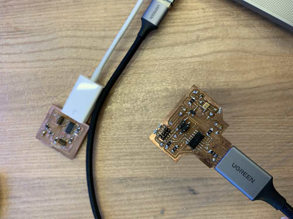
By this time, I had also made my own programming board (documented in Week 3), so I wanted to use it to bootload the microphone board. I plugged everything in and then ran lsusb. My board was recognized by my computer! I then followed Jake's guide: I already had edbg installed from December 2020, I downloaded the correct binary for the bootloader (I was using a SAMD11C microcontroller) and placed it in the correct place (under the edbg folder on my computer), and then I ran the proper command to burn the bootloader. Unfortunately, I got an error that even Anthony hadn't seen. The error said that "Error: incorrect DAP_INFO_CAPABILITIES size".
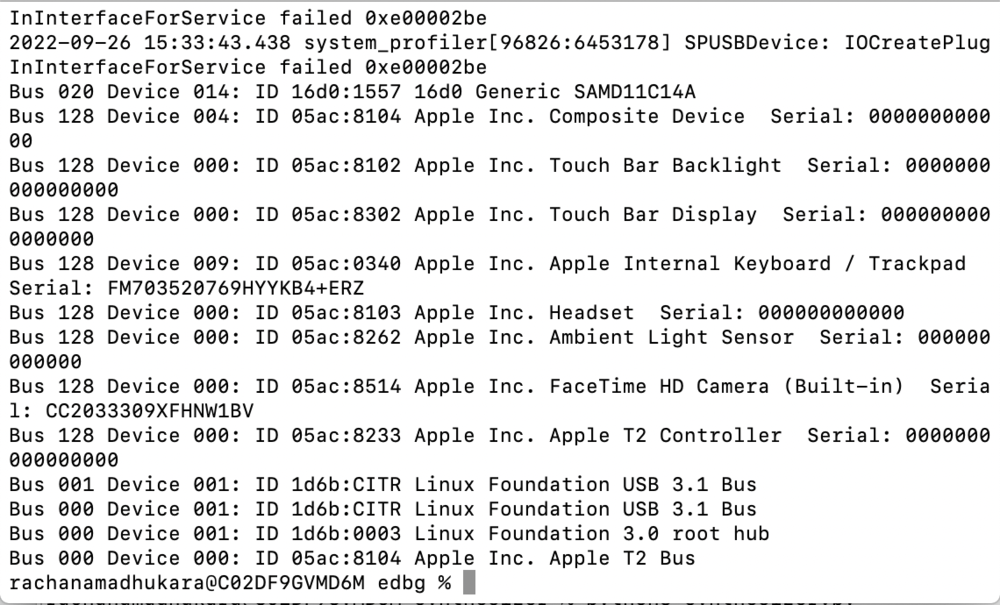
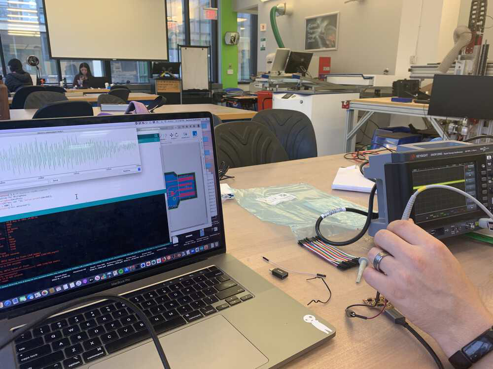
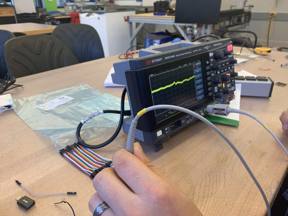
After some Googling, I found another fab site that had the same issue. However, there was no resolution presented there, so I still do not know how to fix this issue. It seems to be a Mac specific issue. Therefore, for my board, I just used the Atmel ICE to burn the bootloader using edbg. This time, everything worked properly! Now I could move onto to programming, which was pretty straightforward. Using the Arduino Serial Plotter (second picture) or using an oscilloscope (third image), you can see the wave form change when one makes a louder noise. The microphone was working!

Finally, here are the working files: Schematic PCB Arduino Code