Week 7
Embedded Programming
Designing the Board
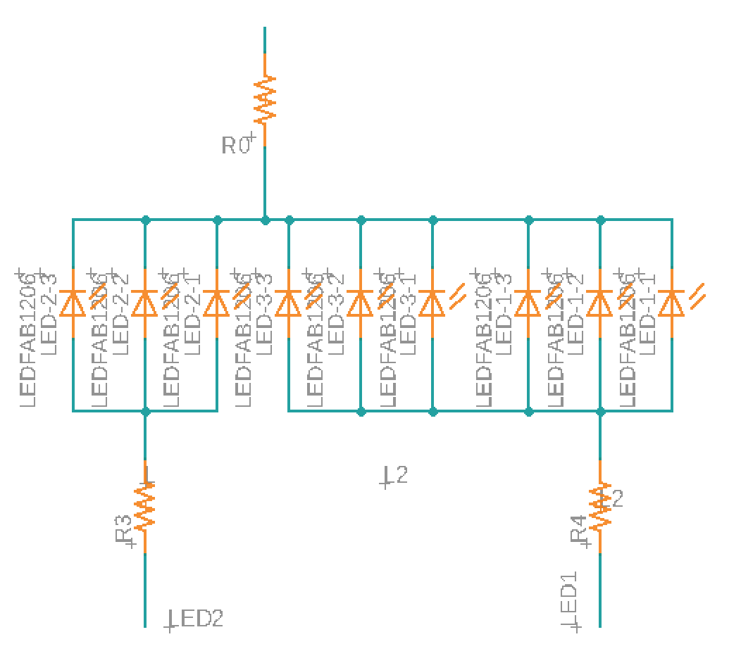
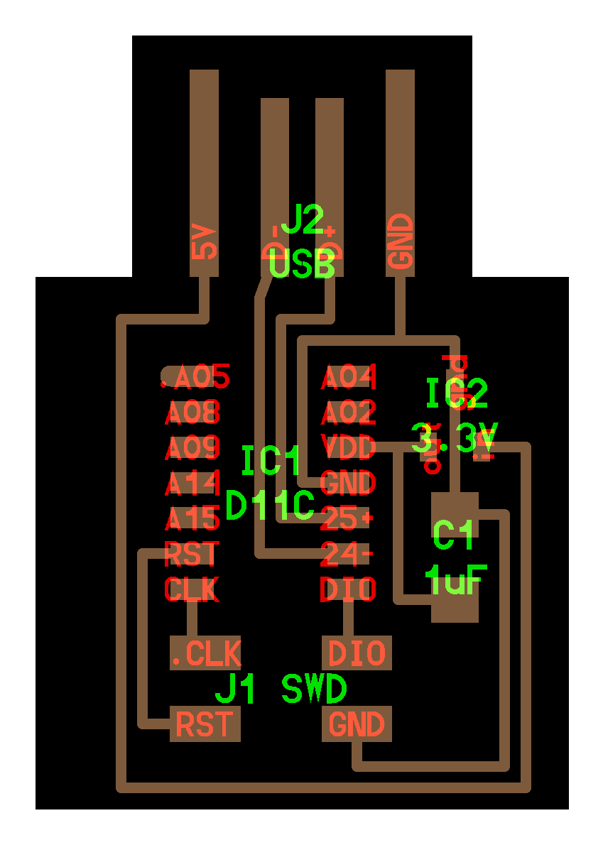
I created a new board for this assignment because I had missed a previous week due to sickness. I selected to reproduce the ATSAMD11C echo board with a 4-pin connector ( Link ). However, I also added a tactile switch button and 9 white 1206 LEDs to the schematic. In order to use these I also added 4 new resistors: 2x100 ohm (LEDs), 1x 10000 ohm (button), and 1x0 ohm (board layout to go over a wire).
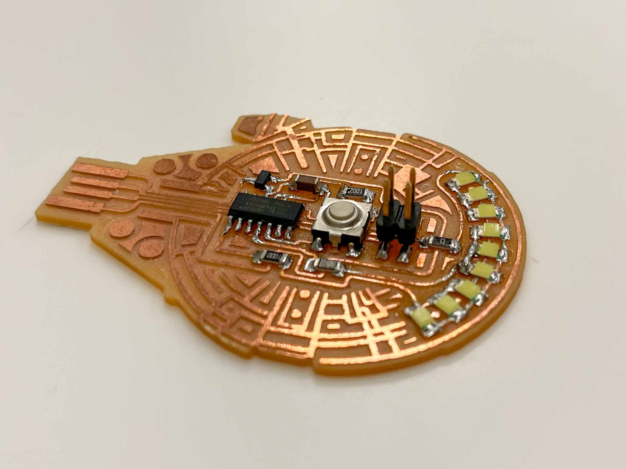
The big takeaway from the design it mainly in the way i configured the lights. I separated the pins for middle 3 lights vs the outer 6 (3 on each side) to control them separately. This required two different in routes, each going through a resistor. Then I wired all 9 through the same 0 ohm resistor (to jump a trace) and connect to ground (image on left).
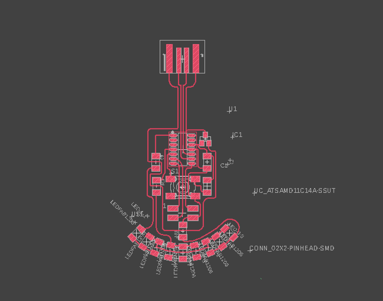
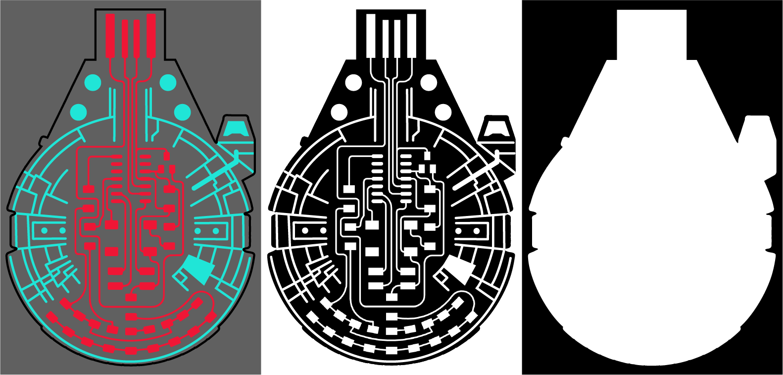
I also wanted to have fun with this assignment without too much complication, so I decided to stylize the board to resemble the Millenium Falcon from Star Wars. This requires initial circuit design in fusion and additional design complete in Adobe Illustrator.
I also wanted to have fun with this assignment without too much complication, so I decided to stylize the board to resemble the Millenium Falcon from Star Wars. This requires initial circuit design in fusion and additional design complete in Adobe Illustrator.
Eagle to InDesign Artistic PCBs
Step 1: Import image to illustrator and got to Object>Transform>Scale. Type in 50% for uniform scaling.
Step 2: Import image to illustrator and got to Object>Transform>Scale. Type in 50% for uniform scaling.
Step 3: Copy the image and use the trace function to help with you design layout (the copy is optional)
Step 4: Design as you will, but it is good to use the correct line width for your designed traces. For example, our PCB milling machine uses 1/64" bits for the traces, so I made that my line width as well.
Step 5: After you're done, export your image as a PNG and set the ppi to 1000.
Milling
You can review week 3 for instructions on milling. I used the same setup for this project, however my first run through had an issue with the USB port being too small. This was completed through a simple adjustment to the outline by taking measurements from Eagles USB port layout and adding it to my Illustrator file (0.3447 in x 0.4204 in).
Soldering
There is also nothing particularly new discovered in my soldering this week. However, I had a new appreciation for checking for mistakes that can be extremely small.
One mistake that was discovered was an error in the PCB design. I was missing a connection between the middle 3 LEDs on the input line. To fix this issue, I decided to bridge solder across the connections.
One approach to this is trying to drap heated solder across the 2 points. This might work, but it is quite tenuous and it can be thin. Instead, I cut a piece of solder lond enough to bridge the 2 sides and heated the ends (video on right).
Programming
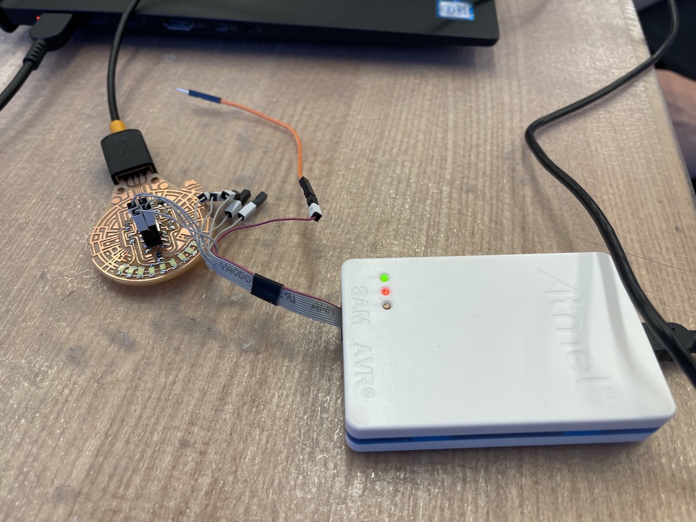
To begin, we needed to install the Bootloader to allow our board to properly communicate with Arduino. I completed this with the help of my TA. The file for the ATSAMD11C bootloader can b found here.
For my program, I wrote it using Arduino, not AVR. I chose this because of familiarity and that speed wasn't going to be critical.
I started by using some code I found online and then modified (Foundation code by David Mellis). The code is simple and uses the tactile button as an on/off switch for an LED. A few things I wanted to change are:
- Add a second input for LEDs (one is inner, the other outer)
- Turn the default state to be OFF
- Turn to simulate a 3-state switch (1-all off, 2-inner on, 3-all on)
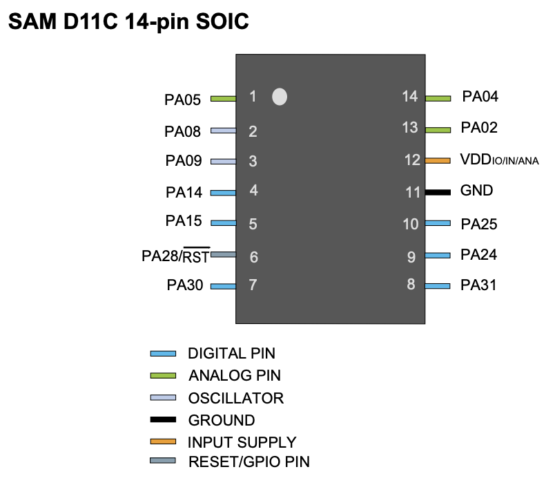
You want to start by setting your inputs and outputs correctly. Using the Pin Layout diagram from the ATSAMD11C data sheet, you can see I used 5 (Outer LEDs), 14 (Inner LEDs), and 15 (Tactile Switch).
/* switch
 *
 * Each time the input pin goes from LOW to HIGH (e.g. because of a push-button
 * press), the output pin is toggled from LOW to HIGH or HIGH to LOW. There's
 * a minimum delay between toggles to debounce the circuit (i.e. to ignore
 * noise).
 *
 * David A. Mellis
 * 21 November 2006
 */

int inPin = 2; // the number of the input pin
int outPin = 13; // the number of the output pin

int state = HIGH; // the current state of the output pin
int reading; // the current reading from the input pin
int previous = LOW; // the previous reading from the input pin

// the follow variables are long's because the time, measured in miliseconds,
// will quickly become a bigger number than can be stored in an int.
long time = 0; // the last time the output pin was toggled
long debounce = 200; // the debounce time, increase if the output flickers

void setup()
{
 pinMode(inPin, INPUT);
 pinMode(outPin, OUTPUT);
}

void loop()
{
 reading = digitalRead(inPin);

 // if the input just went from LOW and HIGH and we've waited long enough
 // to ignore any noise on the circuit, toggle the output pin and remember
 // the time
 if (reading == HIGH && previous == LOW && millis() - time > debounce) {
 if (state == HIGH)
 state = LOW;
 else
 state = HIGH;

 time = millis();
 }

 digitalWrite(outPin, state);

 previous = reading;
}
The big takeaway from my programming is the 3-way switch. It is a basic if-statement logic that contains the 3 possible starting states.
- State 1: Inner - Off & Outer - OFF
- State 2: Inner - ON & Outer - OFF
- State 3: Inner - ON & Outer - ON
The program confirms the state it is in and then pushes it to the next state by making the appropriate ON/OFF change(s).
/* This is a modified version of David A. Mellis's work(21 November 2006) : https://www.arduino.cc/en/tutorial/switch
 *
 * switch
 *
 * Each time the input pin goes from LOW to HIGH (e.g. because of a push-button
 * press), the output pin is toggled from LOW to HIGH or HIGH to LOW. There's
 * a minimum delay between toggles to debounce the circuit (i.e. to ignore
 * noise).
 *
 * David A. Mellis
 * 21 November 2006
 */

int BUTTON = 15;     // button pin
int LEDin = 14;    // inner LEDs pin
int LEDout = 5;    // outer LEDs pin

int INstate = LOW;   // the current state of the inner LEDs
int OUTstate = LOW;   // the current state of the outer LEDs
int reading;      // the current reading of the button
int previous = LOW;  // the previous reading of the button

// the follow variables are long's because the time, measured in miliseconds,
// will quickly become a bigger number than can be stored in an int.
long time = 0;     // the last time the output pin was toggled
long debounce = 200;  // the debounce time, increase if the output flickers

void setup()
{
 pinMode(BUTTON, INPUT);
 pinMode(LEDin, OUTPUT);
 pinMode(LEDout, OUTPUT);
}

void loop()
{
 reading = digitalRead(BUTTON);

 // if the input just went from LOW and HIGH and we've waited long enough
 // to ignore any noise on the circuit, toggle the output pin and remember
 // the time
 if (reading == HIGH && previous == LOW && millis() - time > debounce) {

  if (INstate == LOW && OUTstate == LOW) { // When no lights are on
    INstate = HIGH;
    OUTstate = LOW;
  } else if (OUTstate == LOW && INstate == HIGH) { //When only the inner lights are on
    INstate = HIGH;
    OUTstate = HIGH;
  } else if (OUTstate == HIGH && INstate == HIGH) { //When all lights are on
    INstate = LOW;
    OUTstate = LOW;
  }
 Serial.print("INstate");
 Serial.print(INstate);
 Serial.print("OUTstate");
 Serial.print(OUTstate);

  time = millis();
 }

 digitalWrite(LEDin, INstate); // write the inner LEDs
 digitalWrite(LEDout, OUTstate); // write the outer LEDs

 previous = reading;

}


