Week 10: Output Devices
Goal: Add an output device to a microcontroller board you've designed, and program it to do something
Motivation and Design
This week my goal was to design an example board of how I can set up my modular grow lights for my final project. I didn't order the leds I want to use in time to use them on the board, so I went ahead and just designed it using the LEDs we had available in EDS to show functionality. Once the specific grow lights I want to use arrive, it should be a quick swap out to change the led footprints on the design to fit the new LEDs, and get everything set up with similar code.
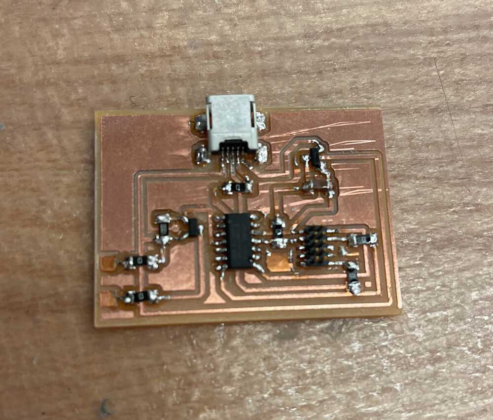
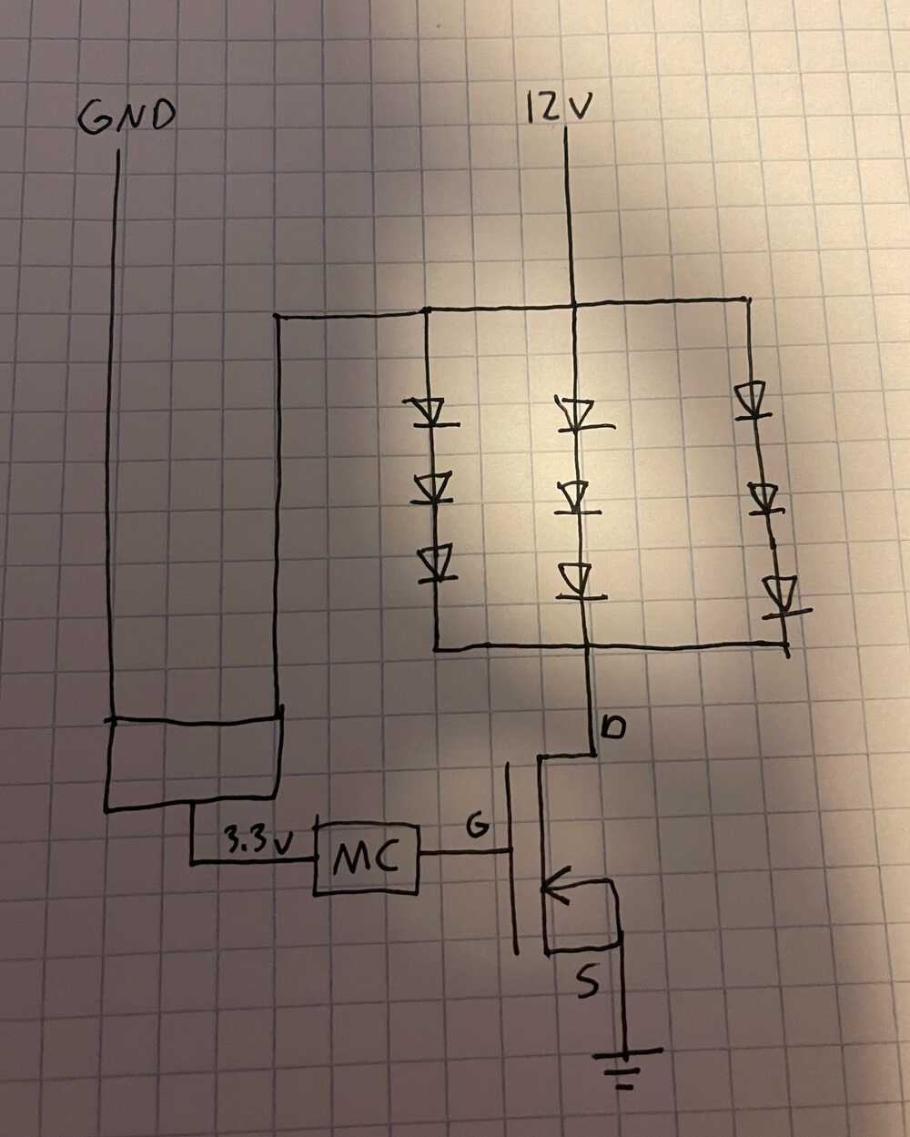
I created two boards this week. The first contains a basic circuit of leds and a resistor which will be attached above each plant in my final project. The second contains the microcontroller to drive the timing of the lighting system. I followed pieces of some of the boards used in past weeks, but opted to use a mini-USB to supply 12V power in order to have enough voltage to power my LEDs in series. I also used a voltage regulator to use the same power source to power the SAMD11C on the pcb. Finally I wanted to have some way for this board to toggle on power to the rest of the system (the multiple circuits with leds) so after talking with Alec and Anthony, I opted to use an N-channel MOSFET to act as a sort of switch. To do this, I hooked up the gate pin to a digital output pin on the SAMD11C, drain to where I will connect the led board circuit, and source to ground. In order to power multiple led boards I planned to have a large parallel circuit starting from this control board and connect them with some jumper wires. In my final project, however, I hope to have copper pads that connect when new pieces are added to add branches to the circuit.
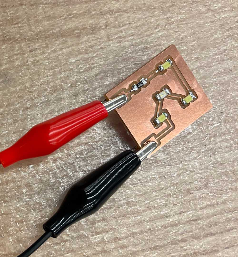
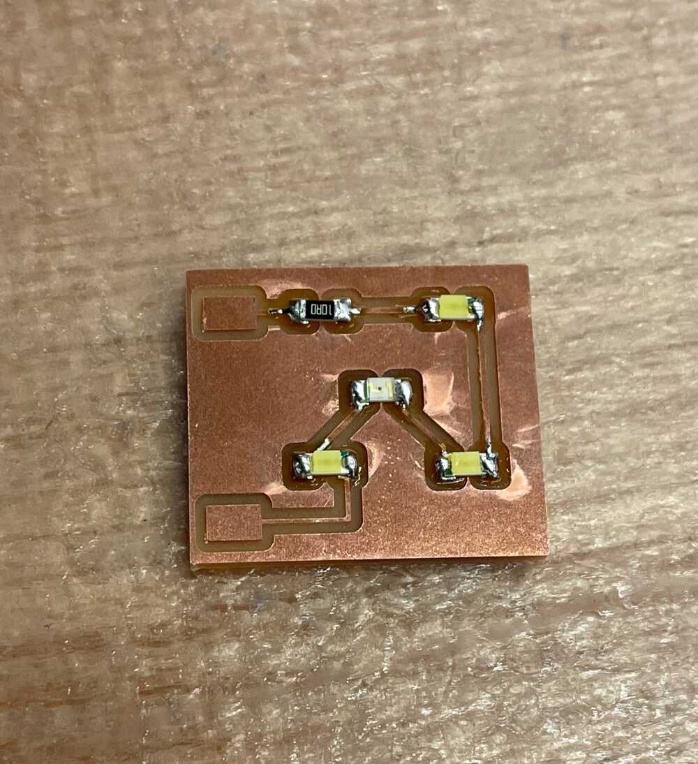
In order to design my LED circuit I first started with an input voltage of 12v since I figured this would allow me to have a decent amount of LEDs in series. From this voltage I added up the sum of the led voltages in the series which summed to 11.9v and subtracted it from the inital 12v input. Then I solved V = IR to get the correct current for the LEDs which was .03 A. This gave me a resistance of .1v / .03 A = 3.33 Ohms. So I went ahead and included a 10 Ohm resistor since this was the next magnitude up from what I needed. This made sure I was not putting too much current through the series. Then I left room on the input and output of the circuit to connect wires.
The Boards
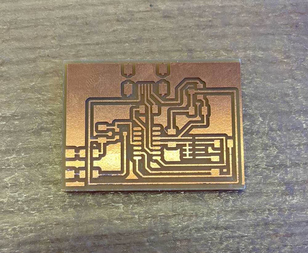
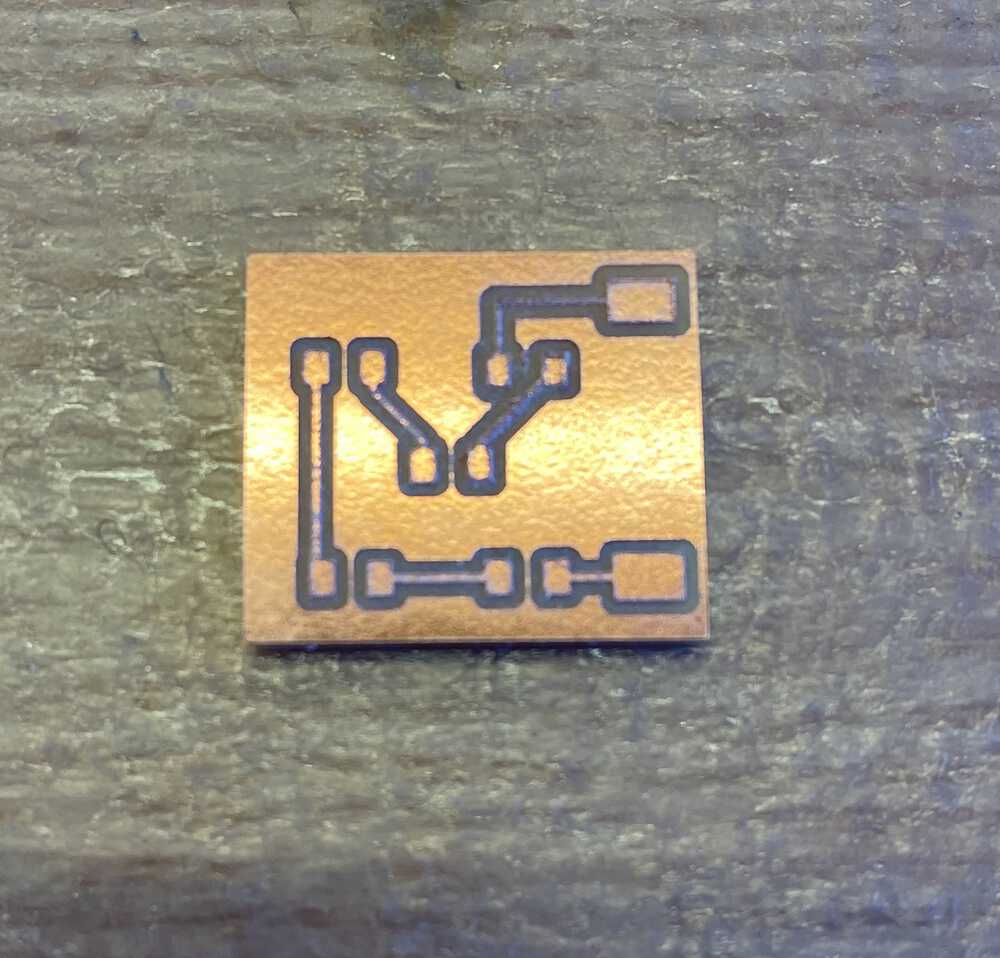
Here are some images of the boards and my overall vision for the circuit..
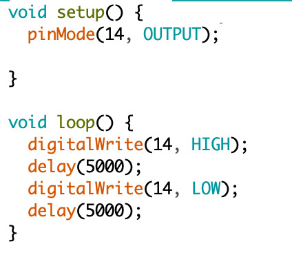
The Code
Programming the board this week was super simple as all I wanted to do was essentially a larger blink board. The code consisted of setting a digital output pin, then alternating high and low voltage to it in order to use the N-channel MOSFET as a switch. Below is the code for this. In my final project, the cycle will look something more on the lines of 12-14 hours rather than 5 seconds.
Failure -> Success
After bootloading my controller board and programming it with the code I wrote, I went to the power supply, turned the knob to 12v and connected everything up then turned it on and my voltage regulator lit on fire and fizzled out. Uh oh. I quickly turned everything off then unplugged the board in order to investigate what happened and with the help of Alec, we found two problems. 1) I ended up connecting my circuit like I was using a P-channel MOSFET instead of an N-channel accidently and 2) I had small pieces of copper between where the jumper wires connected and the copper left over from milling which introduced a short between the connectors (pictured below). After replacing the voltage regulator and fixing my connections to reflect that I had an N-channel MOSFET, I was able to successfully get everything to work as intended.
Some other notable takeaways from this week:
- I should spend some more time and learn the inner workings of some components such as MOSFETS to increase my understanding of how they are used.
- Allocate more time to route PCBs!
- Draw out circuit diagrams before trying to make them in Eagle.