Week 2: Computer-Controlled Cutting
Goal: Cut something On The Vinyl Cutter
Vinyl Cutter
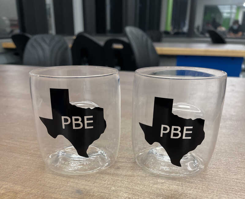
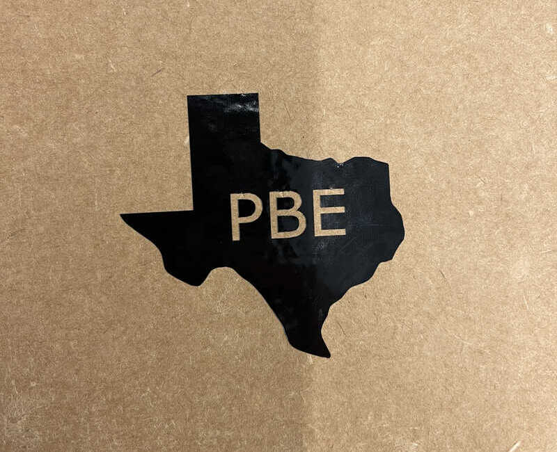
To start off the week I experimented with using the vinyl cutter to apply designs to some glasses I have in my room. I decided on a design combining both my old home (Texas) and my home here at MIT (my fraternity PBE). To right is my final design attached to the cups.
The Final Product
Cheers!
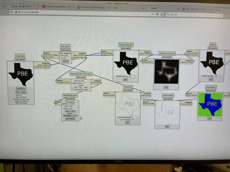
The Software
I designed the Vinyl pattern using GIMP by importing in an image of Texas, typing out PBE within GIMP, filling the shape of Texas in black, and PBE in white, then finally using mods to set everything up for the Vinyl cutter.
Trial Run
Before I put the vinyl directly onto the cups I did a trial run to learn the techniques rolling the vinyl off of the sticky paper and onto its permanent surface. Pictured below is the product of my test run on cardboard.
Week 2: Computer-Controlled Cutting
Goal: Design, Laser Cut, And Document A Parametric Construction Kit.
Design Idea
I was super excited for this week because I would finally be able to start using the machines to bring ideas on paper to life. For my project this week I decided to build a parametrized laptop stand kit. By inputting a height and laptop dimensions the model would increase in size add add a sufficient increases in the number of supports so that people with all different sizes laptops and heights can make and build an ergonomic laptop stand! This week I felt like I got waaaayyyy better at CAD and started to fully understand the power of parametrization.
The Design
Here is an embedded CAD model of the laptop design kit! I opted to have a pretty open design with the thinking that by not having the laptop on a solid surface I could increase the airflow getting to all sides of the laptop casing to hopefully help mitigate overheating.
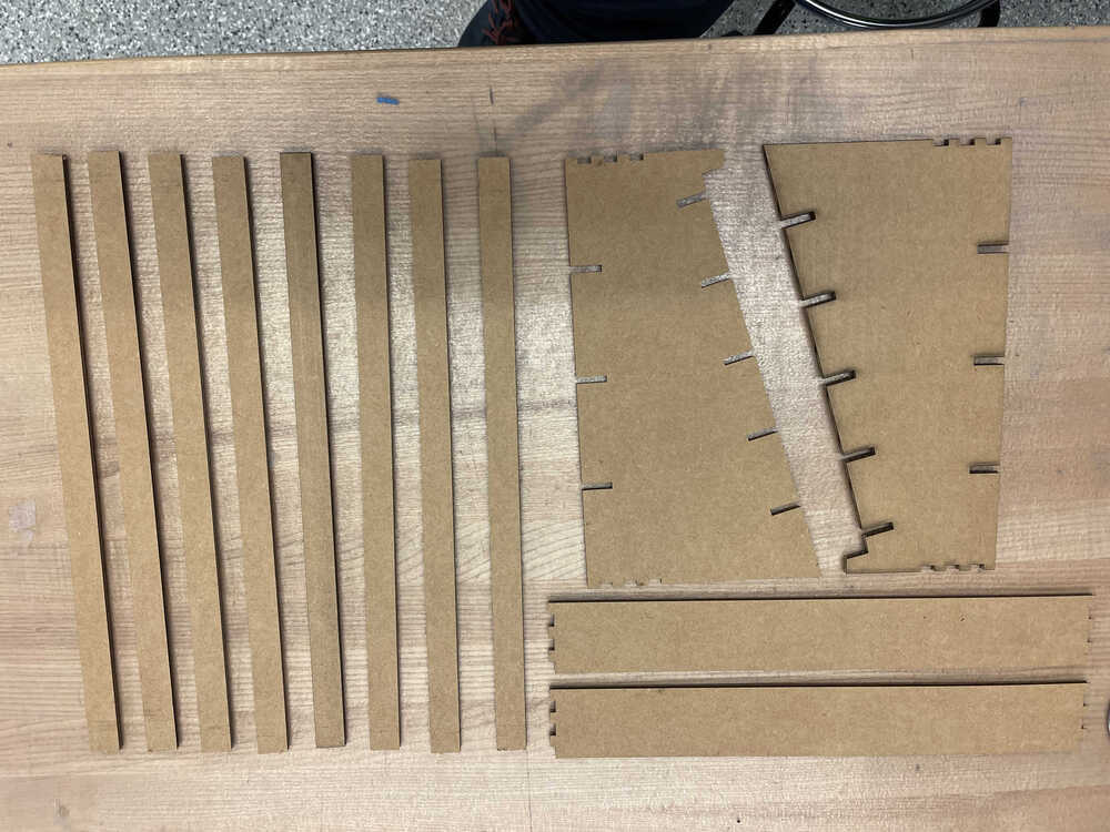
Cutting
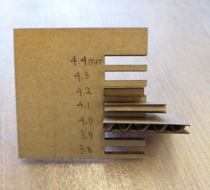
In order to laser cut the design I used the parameters for power that my group came up with for the group exercise this week and ended up putting the power to 100% and speed to 8% on the larger of the two laser cutters. I also accounted for the kerf in my parameterization of the design and put the cardboard width in as 4.1 mm to account for it. The result of my laser cut pieces is below.
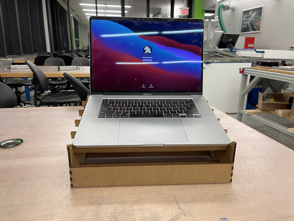
Laptop Stand In Action
Piecing it all together I was left with a nice laptop stand that easily supports my laptop!
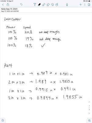
Group Project
The group project this week was to characterize our laser cutter's focus, power, speed, rate, kerf, and joint clearance types. To do this we varied each of these variables and concluded that the settings that worked best for a flat piece of cardboard were Power: 100%, Speed: 10%, Rate: 1000 PPI. We also tested what it would take to only cut through the first layer of cardboard and found that dropping the power down to 40% led the laser to only cut through half the board. We did similar on the smaller laser cutter in the EECS lab and found the power remained optimal at 100%, while the speed worked well at 18% since the laser is slightly stronger. Finally we measured experimentally to find the kerf by cutting out many pieces and measuring how the size compared to our models. On the larger of the two lasers we found that anywhere from 4.0mm to 4.2mm worked well for joint clearance. For the smaller of the two lasers we found the kerf to be ~.3175mm.