Week 3: Electronics Production
Goal: Make an in-circuit programmer that includes a microcontroller: Mill and stuff the PCB, test it to verify that it works
Milling the board
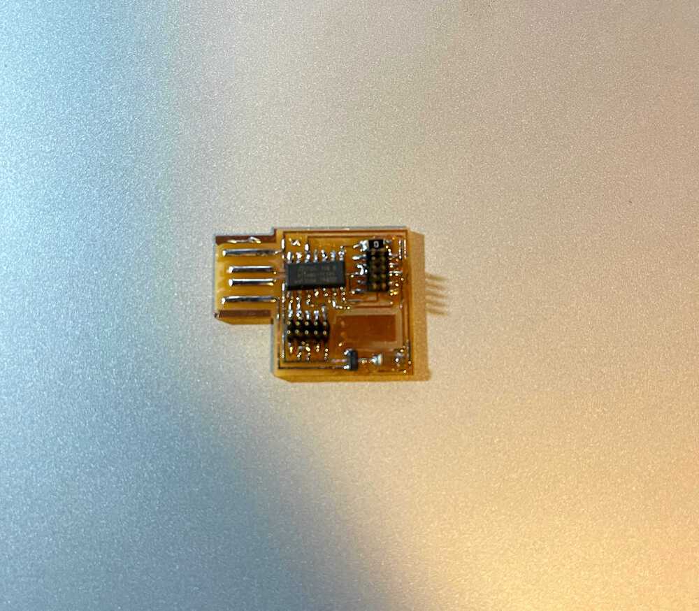
Milling the board this week was suprisingly nerve-wracking. After being warned what felt like a thousand times not to break the bit, calibrating and then finally milling the board caused great suspense every time the bit started to move towards the copper plate. However, in the end, no accidents were made and I successfully milled the hello.CMSIS-DAP.10.D11C board pictured to the right!
The Design
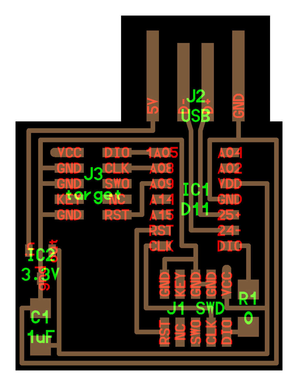
Although I do not yet understand all that goes into this board, I have learned enough this week to at least know how to search out the right components (mostly just ask Anthony lol) and mill it.
Milling
This week I milled the board on the Roland SRM-20 and learned how to calibrate the depth of the cut to preserve the mill bit. I did not have much time this week to experiment with redesigning the board design itself so I was boring and just went with the given design, however it turned out looking great!
Milled Board
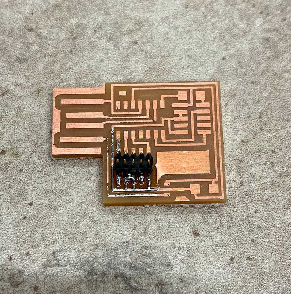
Oops! I forgot to take a photo before starting to solder, but here you can see the traces milled by the Roland machine.
Soldering
As a complete newbie to soldering I was rudely awakened to the difficulty of this task. Boy was I wrong in expecting this to be a quick 15 minutes project this week after watching Anthony quickly exhibit the basic soldering techniques. I struggled greatly with this task and spent about an hour attaching, unattaching, solder wicking, and more generally just messing up and trying to fix my mess ups. However, at the end of the day I now feel more comfortable soldering and learned some valuable lessons in how to move components once already attached, remove solder, and check to make sure things look right. And hey, despite it not looking the most pretty I was able to successfully test out and use the board!
The Result
She ain't pretty, but she works.