Week 4: 3D Scanning and Printing
Goal: Design and 3D print an object that can not be made subtractively.
Group Project
This week's group project was to test the design rules of our 3D printers. The EECS lab consists of 2 Sindoh's and 1 Prusa so we went ahead and ran tests on both to learn their capabilities for overhangs, clearances, infills, and bridges. Examples of these can be found here at our teams group page (Note: Sindoh = Black, Prusa = Yellow). Here are some things I learned this week:
Personal Tests
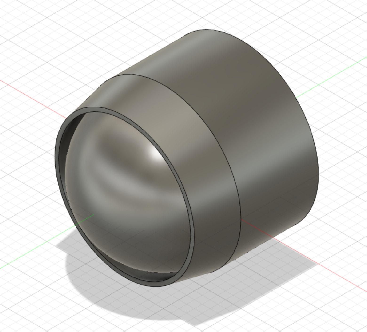
Outside of the template tests we ran as a group I wanted to figure out if it would be feasible to have a free moving sphere to be used as wheel. I took the idea from ball point pens and I wanted to design a car using a similar feature. Before I CADed the whole thing, however, I decided to test out what clearance I wanted around the sphere within the casing to allow for the best movement. Below is the cad and the test print I ran. I ended up opting for a 1.5mm buffer around the sphere on my final design as I found that allowed me enough room to break the sphere free from any unwanted attachments to the outside of the casing and allowed the sphere to move easily.

The Design
As mentioned earlier, I wanted to create something with moving parts that used the ball point pen feature. Naturally, I fell on creating a small car! And what better to model it after than an avocado! Below is my CAD which took me far to long for what I thought would be a straight forward design. Throughout the design process I learned that it is much more difficult to design stuff in 3D to be printed than it is to design stuff in 2D as we did for the laser cutting week. I found myself constantly asking myself whether things would be touching the bed, supported enough, and at gradual enough of an angle to avoid spaghetti-ing. Below is my CAD.
The Printed Car
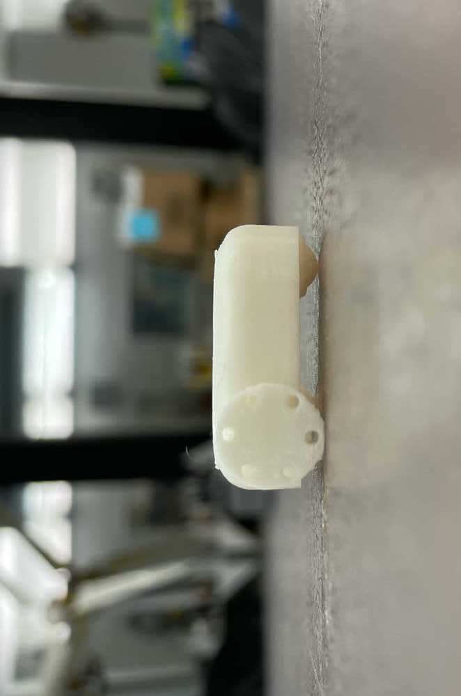
After the car was printed, the real challenge was removing the support material, breaking free any connections within the axel, and doing the same for the spherical wheel. With the component being at its current size I had to be super careful not to break the axel itself or the cage surrounding the sphere while removing the supports. I ended up using an exacto knife to free the sphere and pushing the axel back and forth to free its motion. Unfortunately, while snipping away the supports I cut off part of the left wheel. Here is a side view of the car to show the wheels making contact with the table and supporting the vehicle.
Movement
Suprisingly enough I ended up not breaking the car completely while breaking free the spurious connections and the following videos show it moving!
More Movement
I put the car on sandpaper to allow for the wheels to grip better since there is some friction along the axel and spherical wheel that has to be overcome and the grip of the wheels on the table top was not enough to do so.
Week 4: Scanning
Goal: 3D scan an object
First Attempt
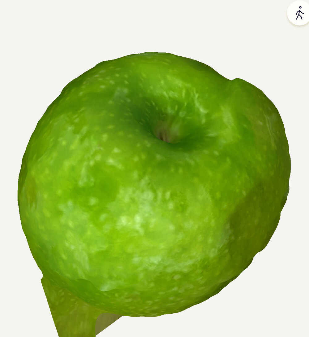
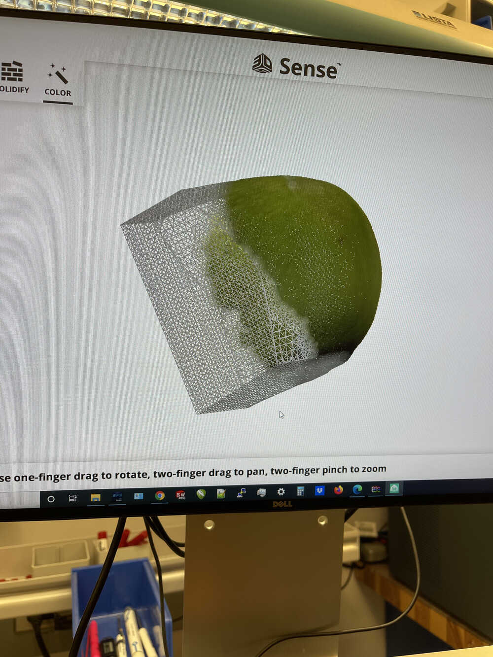
My first attempt at scanning utilized the scanner within the EDS lab and I attempted to scan an apple. On my first few attempts I had a very difficult time. I think the size of my object made it difficult for the scanner to keep track of where the object was located in the frame so I had to very slowly rotate around the apple and even the slightest jolt of movement would force me to restart. After getting about 2/3rds of the way around the apple I was too scared to risk it and go for the back so pictured is the result of that scan.
Photogammetry
I was interested in finding a photogammetric approach to this weeks task after being somewhat frustrated at how slowly I had to move around my apple in my first attempt. I remembered people saying Meshroom was not doing a very good job so I decided to try out an app on my phone called polycam. I attempted to use both lidar (poor results on such a small object) and normal photogammetry and the results were decent (especially for a mostly free tool). After completing the scan, however, I learned that in order to actually output the model to an STL or other useful file type, a subscription was required :(.