Week 7: Embedded Programming
Goal: Read the data sheet for my microcontroller and program my board to do something.
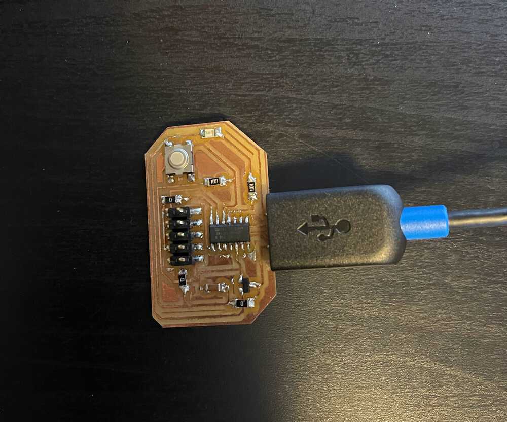
My Programming Board
I was quite busy this week attempting to secure a job for after school so I did not have time to explore this weeks material as much as I wanted. I will note here that you should check my final project page for a more interesting application of embedded programming in the coming weeks. I will be designing my own grow light system controlled by some sort of PCB to handle turning on and off lights based off time of day. For this week, however, I simply programmed the boards we made 2 weeks ago (see week 5 page) to turn on and off an led with the button. Below is the board I programmed.
Setting Up Environment
In order to program the board to do what I wanted, I decided to use the Arduino IDE since I have used it before and it makes development quite simple. The process of getting things set up went as follows:
- Go to https://github.com/qbolsee/ArduinoCore-fab-sam and scroll down to the installation section and follow the instructions under "MattairTech D|L|C Core Installation". Note: I am writing this based off my installation on Mac OsX.
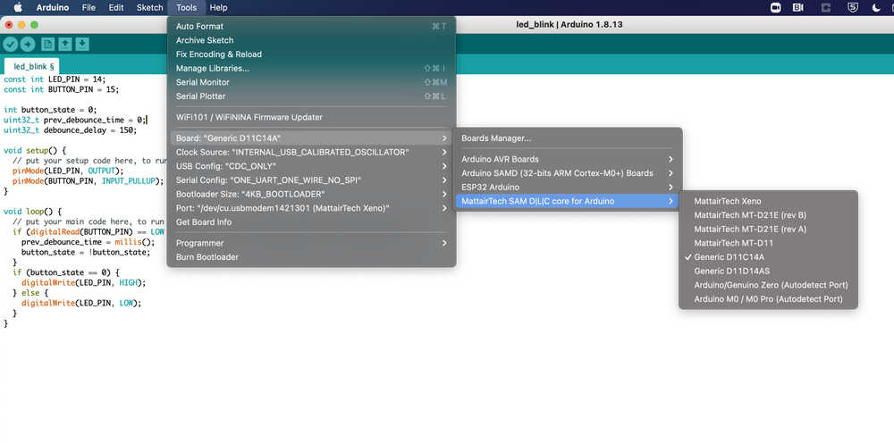
- After following the steps, since I was using a SAMD11C14 board at the step where you choose the board I clicked the one corresponding to Generic D11C14A. (Pictured below)
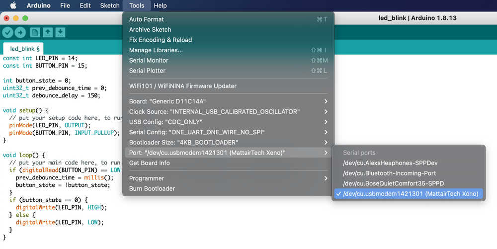
- I then changed my COM port to that of the device. (Pictured below) and was able to begin programming!
Programming
After getting all set up in the Arduino IDE environment and connecting to my board through
my computers USB port, the next step was to actually program it to do what I wanted: Turn on and off
and LED. To do this I started by looking up the pin out of my board in the SAMD11C data sheet. Below is
the pinout I used for reference. From this I gathered that my button was connected to pin 15 and my led was
connected to pin 14 so I set this as constants in my code. Next, in the set up method I set the pins to the correct
function (input or output). Arduino has a nice built in function, pinMode(), that lets you set this. In the code
you can see that the LED pin was specified to be output since we want to output voltage to it to turn it on.
On the other hand the button is used as input since we want to read the voltage coming in to determine whether the
button was pressed or not. An interesting note is that the SAMD11C has a build in pullup resister so we can tell the
device to turn that on by specifying INPUT_PULLUP although I built one into my circuit design anyways so I don't think
this is fully necessary.
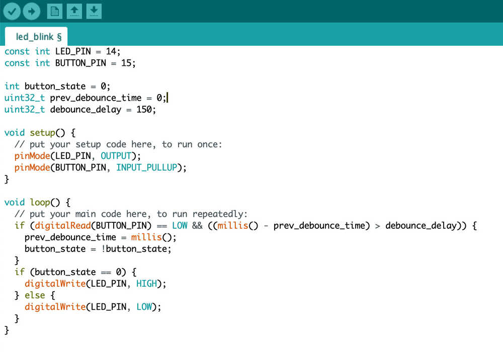
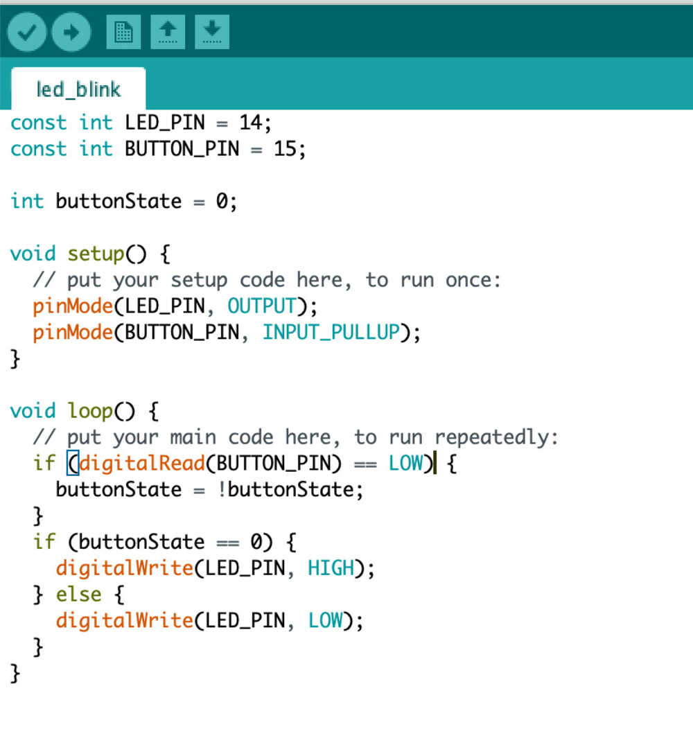
The next part of the code is the loop(). Within the loop I started by setting the button state based off what is
digitally read from the input button pin. If the input read is low voltage (0) then the button is pressed (since
this is how I designed my circuit) and thus we want to flip the button state to be opposite what it was in order to
flip whether the led is on or off. Next I check what the state is. If it is 0 I write high output to the led pin,
supplying it voltage and turning it on, and if it is 1 I send low voltage (0) thus turning it off. As you can see in
the demo video below, however, there is evidence of button bouncing where the state changes mulitiple times per button press.
Fixing Button Bouncing
To fix the button bouncing I went for a simple approach of only checking for button input every 150 ms. In other words, I assume that no one is going to press my button more than a single time within any 150 ms period so I only want to register the button going down once within that time. As you can see in the modified code and resulting video, this simple change in code fixed the issue and I was able to get the system to work nicely!