Week 9: Input Devices
Goal: Measure something: Add a sensor to a microcontroller board that you have designed and read it
Group Project
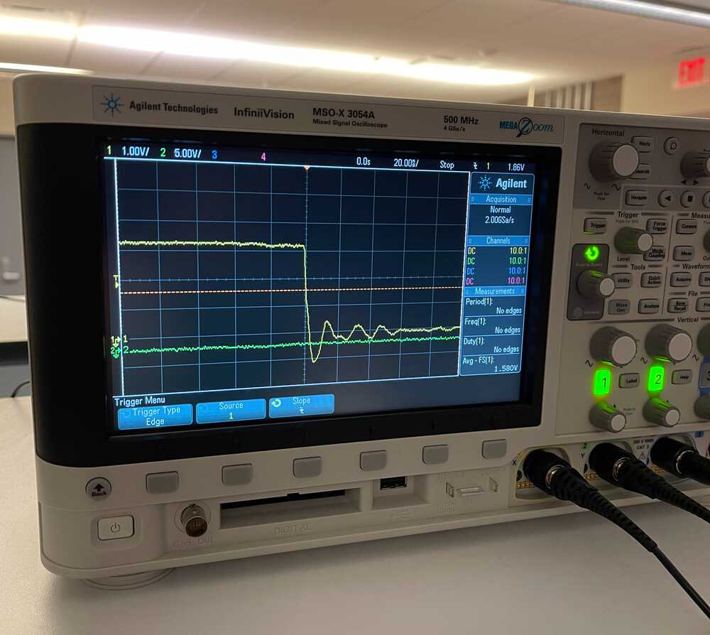
This weeks group assingment was to probe an input device's analog levels and digital signals. We used an oscilloscope to measure this for a button press and were able to see the button bounce in the analog level. We also obversed the digital signals read at different time measurements. When there was a lot of time between digital measurements we were unable to see the button bounce, however at small time steps, you could start to pick up the analog signal and see the button bouncing within the digital signals as well.
Motivation and Design
My final project idea is to make some sort of automated aeroponic system so this week I looked into some of the mechanisms involved that might require input. The main section of the project that I thought input devices would be key is the monitoring of nutrient in water. Upon research I found a couple commercially available sensors that were quite expensive and probably more equipped for large commercial aquaponic and aeroponic farms (link). Instead, I figured for my purposes, measuring the conductivity of my liquid might be enough to know whether the concentration of nutrients in the water is wildly off. After some reading, albeit brief, (open to suggestions if anyone has any) I found a cool guide on how to make a cheap home-made conductivity sensor (link). This week, however, I chose to start small and just work on creating a simple board that measures temperature since temperature affects the conductivity of water and thus must be accounted for.
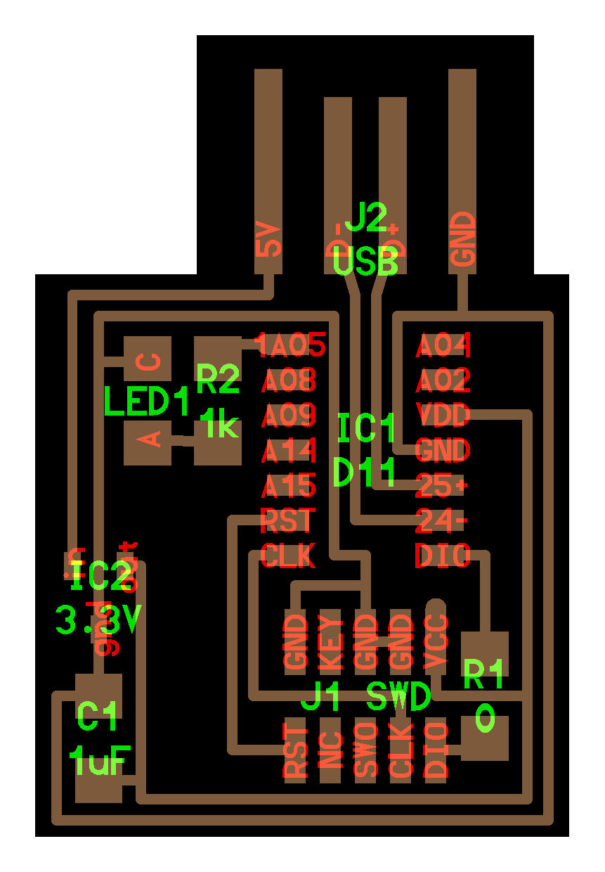
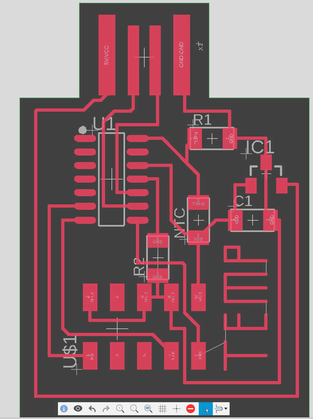
To design the board for this week I borrowed upon previous weeks boards, mainly this and added an NTC thermistor connected to one of the SAMD11C's analog pins. I followed this tutorial somewhat closely in order to learn how to actually read the input from the thermistor and how to set up the circuit to allow for this. After designing the board in Eagle within Fusion 360 I milled the board, stuffed it, and loaded the bootloader onto it to allow programming.
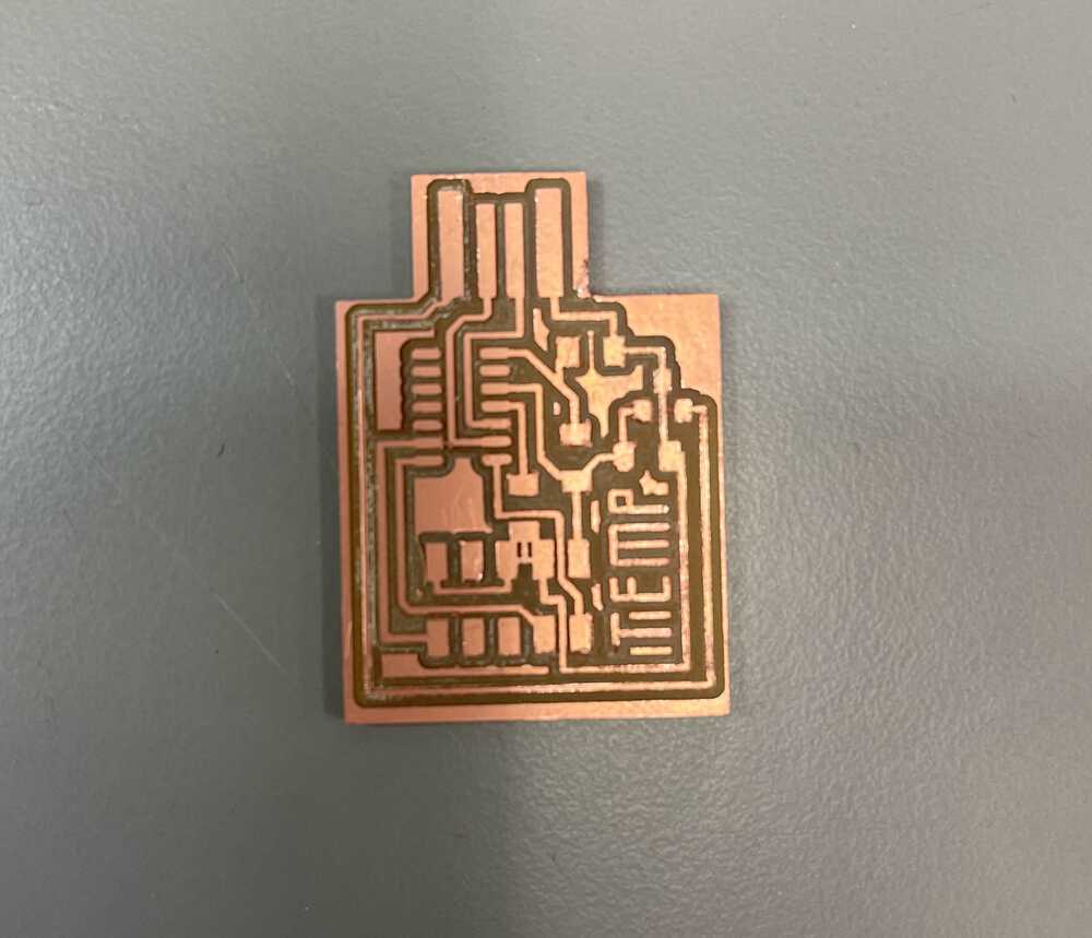
While milling the board this week I had a lot of trouble with the end mill not milling deep enough so I had to play around with the cut depth until it actually went all the way through the copper. I ended up with a value of .007 in. which was almost double the default that had worked in previous weeks. Anthony thinks the sacrificial board might need replacing and this may have caused this. Sadly, I forgot to take photos to document it, but the endmill milled find on one side of the board and barely skimmed the top on the other side.
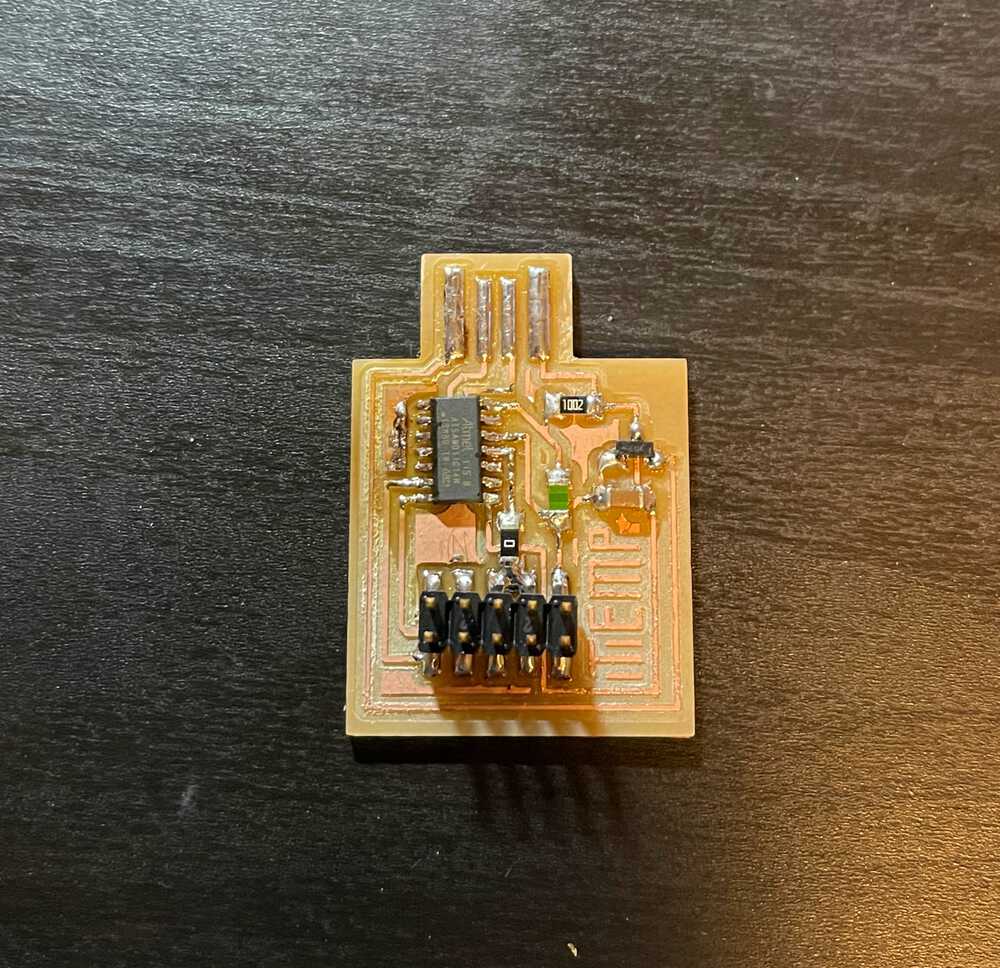
The Board
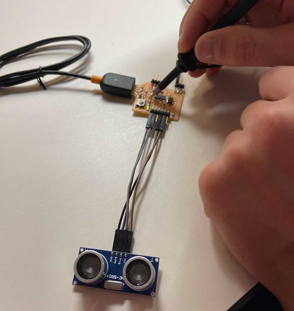
Here are some images of the board making process.
Programming
Programming the board this week brought many issues. First off, after soldering, I was unable to program my board using the programming I milled in the electronic design week so I spent a good deal of time debugging, trying out different orientations of my connectors, and probing connections to look for shorts. Turns out, however, I was looking in the wrong place and the problem was actually with the new board I milled and stuffed this week. I ran a trace under the SAMD11C and when I was soldering the microcontroller onto the board I must have used too much solder and it flowed under the device and connected the RST pin to one of the USB pins. This took way longer than I expected to find, but I was able to fix it by removing the SAMD11C, using solder wick to remove the solder connecting the two paths, and resoldering the SAMD11C back onto the board (carefully this time). After this, everything worked beautifully and I was able to start actually coding.
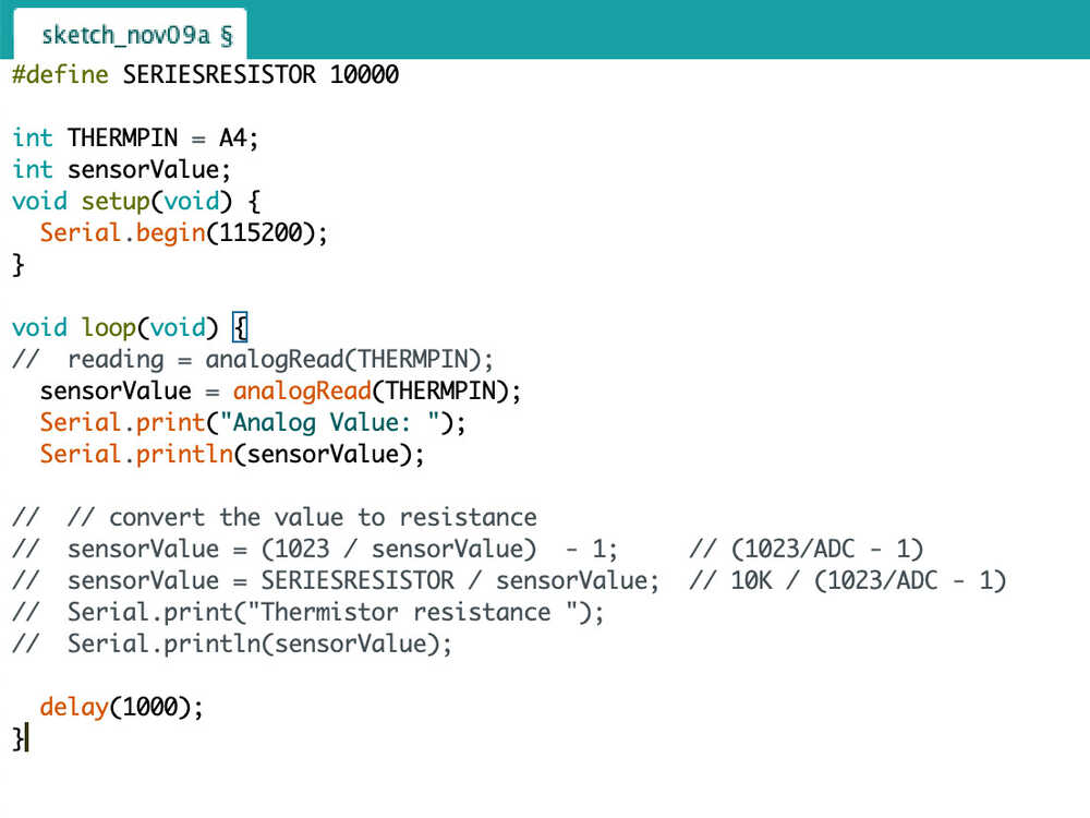
While programming the board, I wrote a simple program based off the tutorial I linked earlier to read the input pin in order to get a voltage. This is converted with the internal ADC into a value between 0 and 1023 which can be calculated by the equation value = Vi * 1023 / Varef where Vi is the measured voltage and Varef is the referance analog voltage. (Note: Varef = 3.3v). We also know that Vi = R / (R + 10k)*Vcc where R is the resitance of our thermistor and Vcc is power supply voltage (3.3v). Combining these we get ADC value = R / (R + 10k) * 1023 since we can cancel out Vcc and Varef since they are both 3.3v. Then, we can get the voltage R by manipulating the equation into R = 10k / (1023/ADC value - 1). Putting this into code, I ran into major problems. For some reason I kept running out of memory on the device and getting the following error: section `.text' will not fit in region `FLASH' region `FLASH' overflowed by 7184 bytes. This only happened when I stored the analogRead value as a float, however, this was necessary in the conversion to find the thermistors resistance so for this week since I still have not solved the issue I just show the change in ADC value. If you know why this happens I would love to chat!
Code and Demo
Here is my code and a demo.