Week 11: Networking & Communications
Networking & Communications: Concept & Planning, Round 1
As the months start ticking down into weeks before our final project is due, I had the idea of doing a larger-scale test run for an art installation. The general idea would be to blend multiple modalities of input to manipulate a data visualization or neural network visualization that would be handled in TouchDesigner come Week 12. The basic idea called for several sensor input peripherals, each connected to an ESP32-WROOM, which talk to a "base station" ESP32, and converts that data back into a serial-over-USB connection to a host computer.As a side note, the really awesome madlads over at Torso Electronics ported over Ableton Link to the ESP32 platform via ESP-idf. This opens up a world of possibilities for embedded systems that can stay in synchronization and phase with music, especially live performances. Unfortunately, as much as I wanted to, I realized I did not have time to learn the tool chain and subtleties of ESP-IDF in a week!
My peripheral of choice was the Luxonis/OpenCV OAK-D-IoT-40 development board, which contain a pair of stereo depth cameras, an RGB camera, a powerful Intel Movidius MyriadX VPU, and an ESP32 (the latter two connected over SPI). The plan was to pull stereo depth maps for point clouds to be used in TouchDesigner, and this had big implications of being able to set up stereo depth imaging cameras far away from the host computer in a visual artist/VJing setup. Initial review of the (sparse) documentation and some Github commentary suggested that this would be possible, but custom-tailored.
However, there were two problems I needed to solve: 1) the 8mbps (~1MB/s) data throughput of SPI, and 2) the wireless connection between all the ESP32s. The former was fairly easily resolved, after discussing with their (commendably heavily-engaged!) development team. Although depth maps can't be compressed via encoding, and a raw 720p depth map is 1.8MB (far more than the SPI bottleneck at 30FPS!), disparity maps (essentially a mono frame from each of the stereo cameras)) can be encoded via H.265, which can then be used to calculate depth on a host. This encoding would take place on the MyriadX (which has more than enough horsepower), and bitstreamed to the ESP32.
The latter was a little more... complicated. I had established that my "base station" ESP32 would run an access point and handle data processing simultaneously (the ESP32 can handle parallel processing over its two cores). Getting the other ESP32s to talk to it was where I ended stuck. I spent the weekend brushing up on my wireless communications protocols:
- UDP: Generally would work, but runs the typical UDP risk of corruption from lost or out-of-order packets - there's a reason it's known as the Unreliable Data Procol! Additionally, a video bitstream wouldn't fit into a single UDP datagram, which would necessitate further overhead in splitting and reassembling across datagrams...
- HTTP POST/GET over TCP: TCP is a lot of overhead, and there'll be a not-insignificant amount of custom code to POST/GET bitstreams.
- MQTT: Needs an MQTT routing station that is fairly computationally beefy (typically, people use a Raspberry Pi) - conservatively, the ESP32 can do ~6 clients, but it's a messaging protocol and not a streaming protocol.
- Point-to-point: The ESP32 can communicate point-to-point over Bluetooth and over ESP-NOW, but unfortunately, I have a many-to-one network schema.
- RTP/RTSP: The most promising of the lot! RTSP is used in many, many, ESP32-CAM setups.
At this point however, I had probably clocked in around 14 hours of research), and in discussing with the various TAs, realized in combination with my networking background, I had surpassed the TA team's knowledge of the topic. It was Monday afternoon, and I hadn't started my board design.
On to the backup plan!
Concept & Planning, Round 2
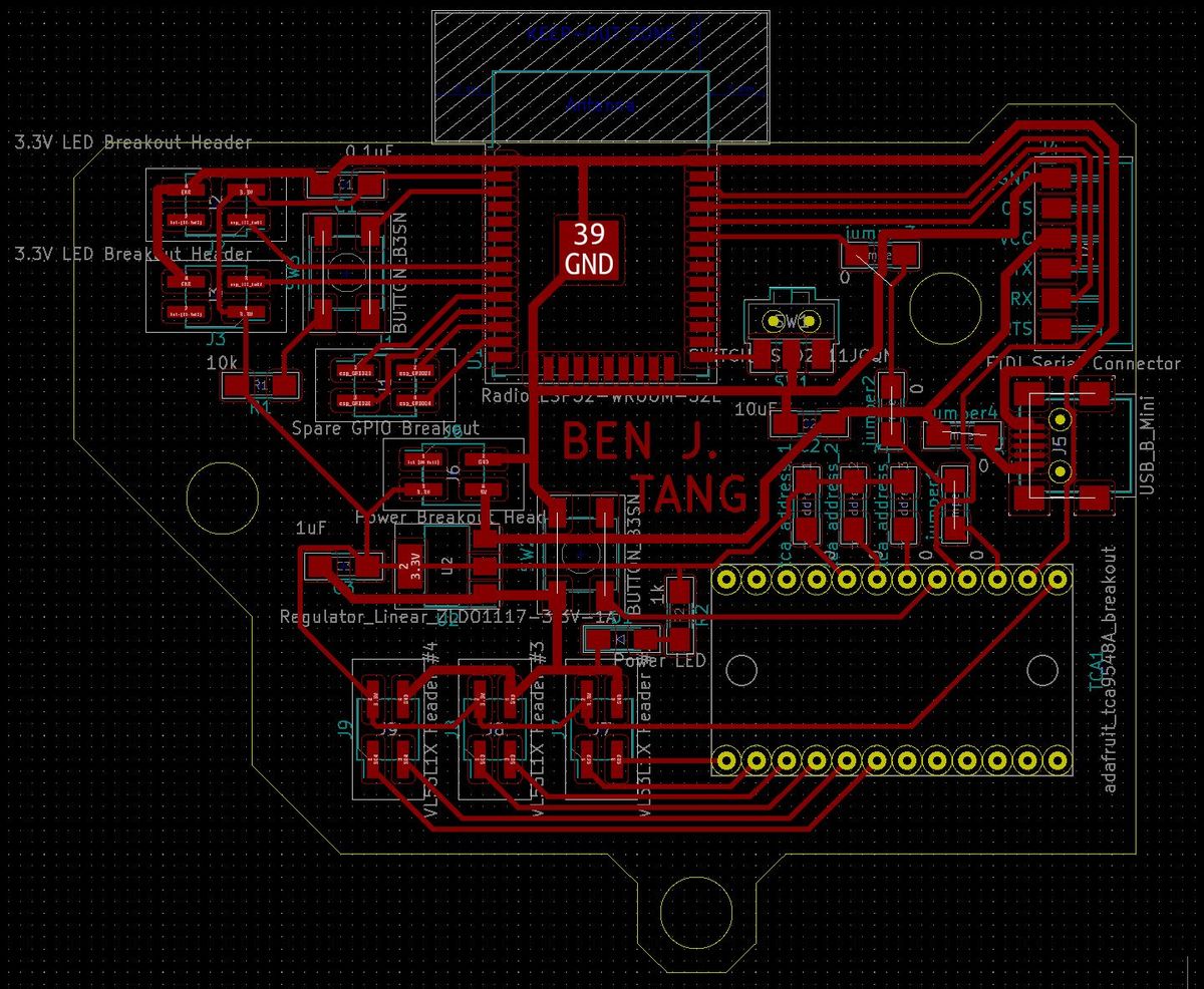
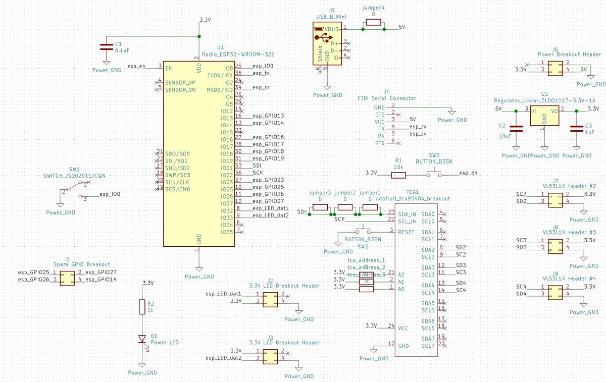
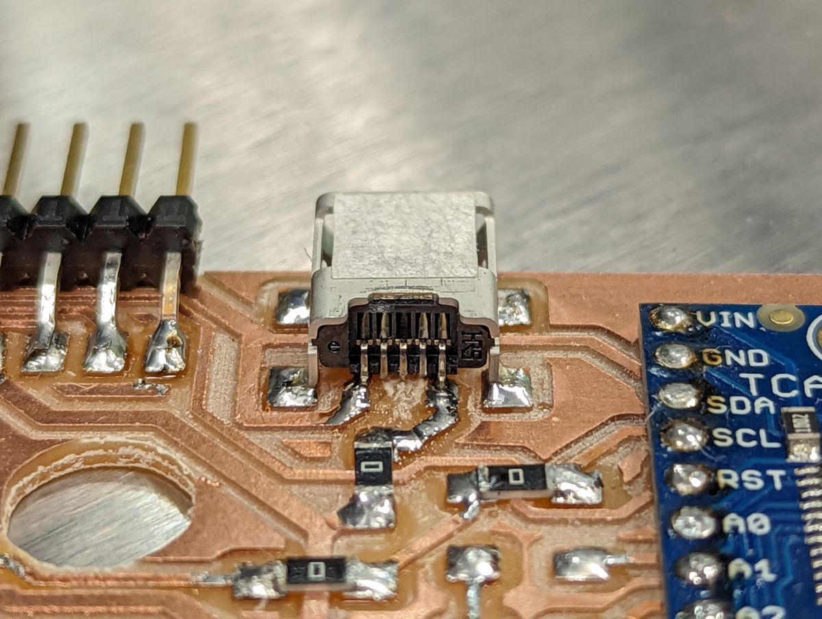
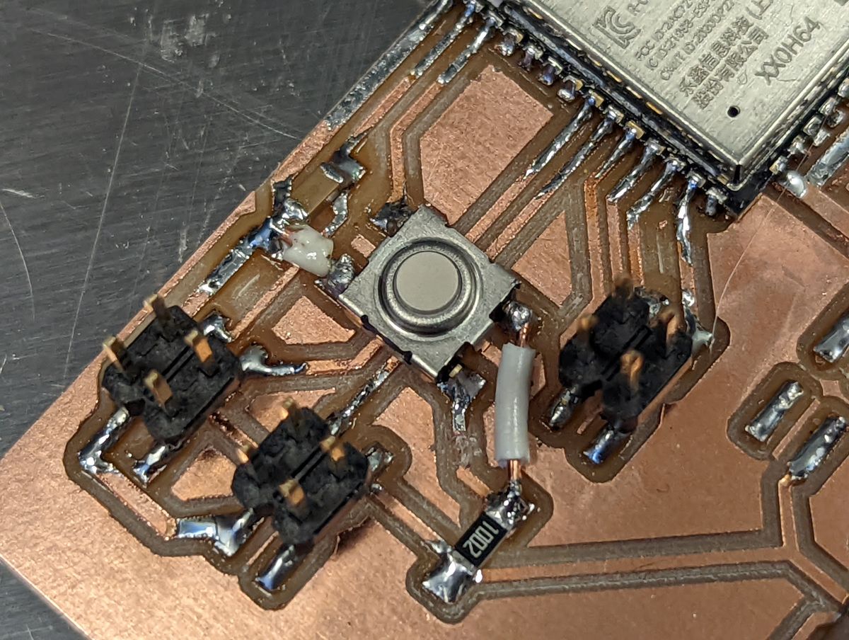
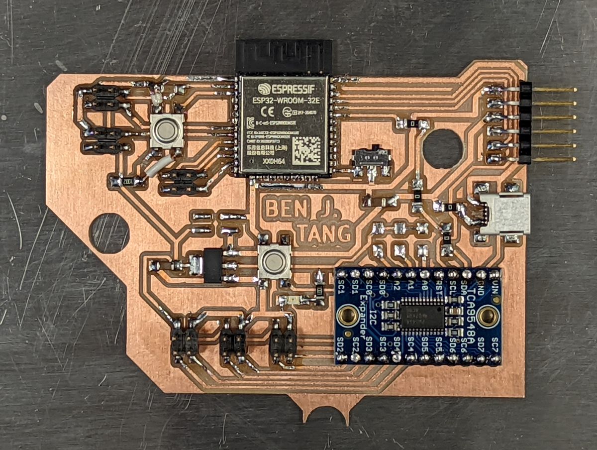
Although my wireless dreams were not to be, I was prepared to downscale to a smaller interactive installation instead. I still wanted to maintain the interactivity of the piece, so I conceptualized the idea of a "bowl" that one could insert their hands into to manipulate something without touching anything (covid-safe!). I also still wasn't sure if I wanted to have the host computer disconnected from the peripherals, so I still used an ESP32 with the plan to attach a trio of Polulu's carrier board for ST's VL53L1X time-of-flight LIDAR sensors and LED headers for running a pair of Adafruit's Neopixel strips at 3.3V, as well as an additional power and breakout header if I wanted to design a breakout board to run them at their full 5V instead, plus a mini-USB socket for providing standalone power without needing the FTDI header.Board Design & Fabrication
Programming & Testing
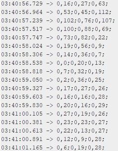
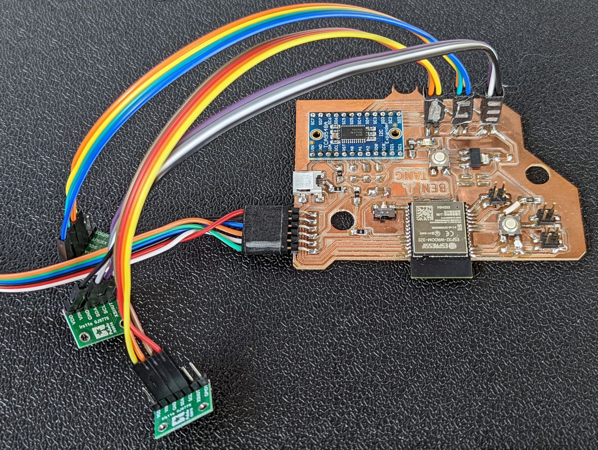
With the board complete, all that was left was programming and testing. The board initially does an I2C scan of every port on the multiplexer and prints it back over serial for debugging purposes. Then, it sequentially switches between the ports to configure them, and repeatedly polls each one, bundles the data into a short "packet" separated by commas for status and range, semicolons for sensor, and newline for readings, and sends that over serial.#include "Wire.h"
#include "VL53L1X.h"
#define MULTIPLEX 0x70
VL53L1X s_dist_2; // tca2
VL53L1X s_dist_3; // tca3
VL53L1X s_dist_4; // tca4
void tcaselect(uint8_t i) {
if (i > 7) return;
Wire.beginTransmission(MULTIPLEX);
Wire.write(1 << i);
Wire.endTransmission();
}
void setup()
{
Serial.begin(115200);
Wire.begin();
for (uint8_t t=0; t<8; t++) {
tcaselect(t);
Serial.print("TCA9548A Port #"); Serial.println(t);
for (uint8_t addr = 0; addr<=127; addr++) {
if (addr == MULTIPLEX) continue;
Wire.beginTransmission(addr);
if (!Wire.endTransmission()) {
Serial.print(" > Found I2C at address X0x");
Serial.println(addr,HEX);
}
}
}
tcaselect(2);
s_dist_2.setTimeout(500);
s_dist_2.init();
s_dist_2.setDistanceMode(VL53L1X::Short);
s_dist_2.setMeasurementTimingBudget(140000);
s_dist_2.startContinuous(140);
tcaselect(3);
s_dist_3.setTimeout(500);
s_dist_3.init();
s_dist_3.setDistanceMode(VL53L1X::Short);
s_dist_3.setMeasurementTimingBudget(140000);
s_dist_3.startContinuous(140);
tcaselect(4);
s_dist_4.setTimeout(500);
s_dist_4.init();
s_dist_4.setDistanceMode(VL53L1X::Short);
s_dist_4.setMeasurementTimingBudget(140000);
s_dist_4.startContinuous(140);
}
void loop() {
// poll the sensors
tcaselect(2);
s_dist_2.read();
tcaselect(3);
s_dist_3.read();
tcaselect(4);
s_dist_4.read();
Serial.print(s_dist_2.ranging_data.range_status);
Serial.print(",");
Serial.print(s_dist_2.ranging_data.range_mm);
Serial.print(";");
Serial.print(s_dist_3.ranging_data.range_status);
Serial.print(",");
Serial.print(s_dist_3.ranging_data.range_mm);
Serial.print(";");
Serial.print(s_dist_4.ranging_data.range_status);
Serial.print(",");
Serial.print(s_dist_4.ranging_data.range_mm);
Serial.println(";");
}In testing, all three sensors correctly increased and decreased in range as a surface was moved closer to and farther away from them.