Week 12: Interface & Application Programming
Concept
Building up to project week, I knew I was going to incorporate TouchDesigner (TD) into it, as I've a strong desire to get better at implementing hardware control systems and/or interfaces with it. TD is a node-based, visual programming language that was an open source fork of the popular Houdini language used in film and cinema for special effects, and has strong integration with various input and output protocols, is performant, and can execute (and access) parallel-running code, such as Python. I have done some past work in TD with generative art, and wanted to continue down that path. I intended to take the three TOF sensors from the previous week and use it as a three DOF control system for TD.Hardware Systems Integration Experiments
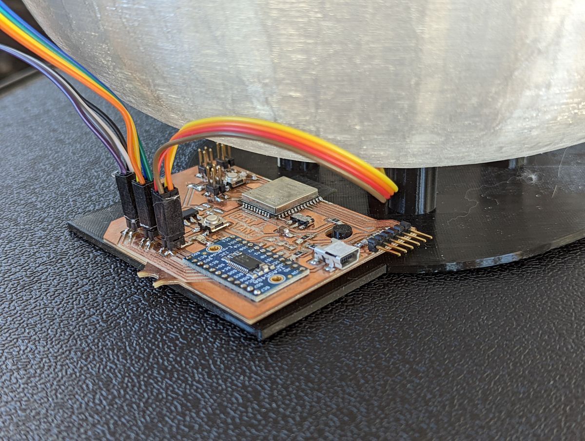
TouchDesigner Implementation
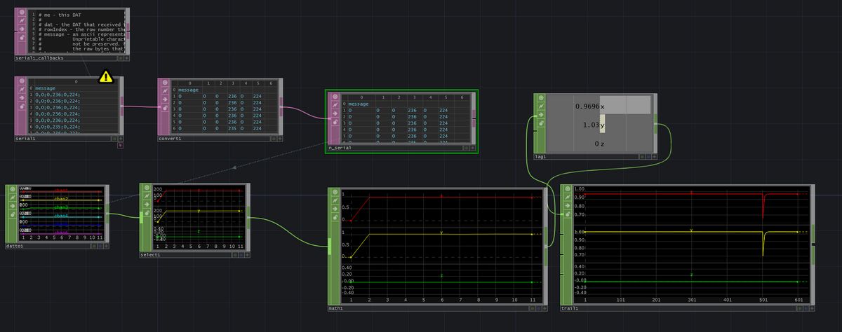
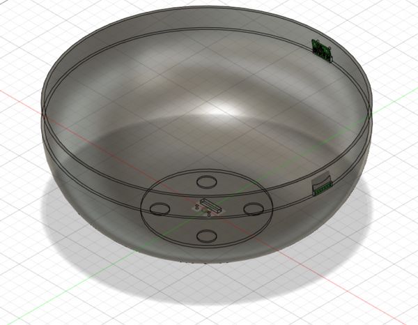
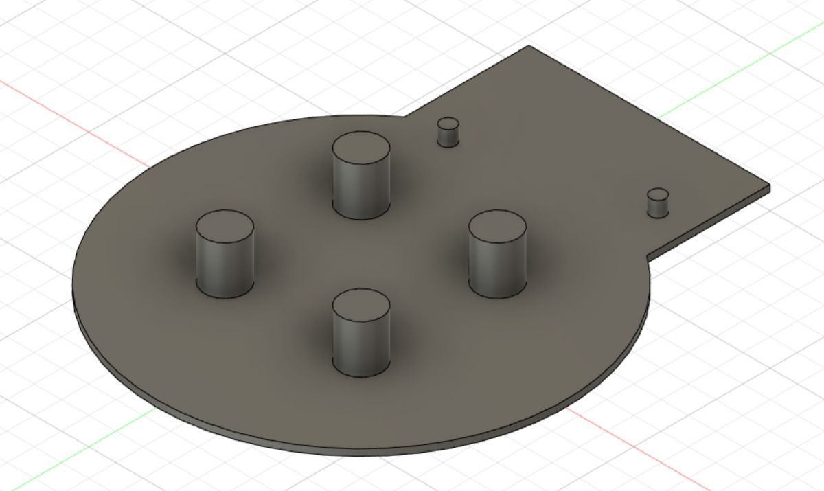
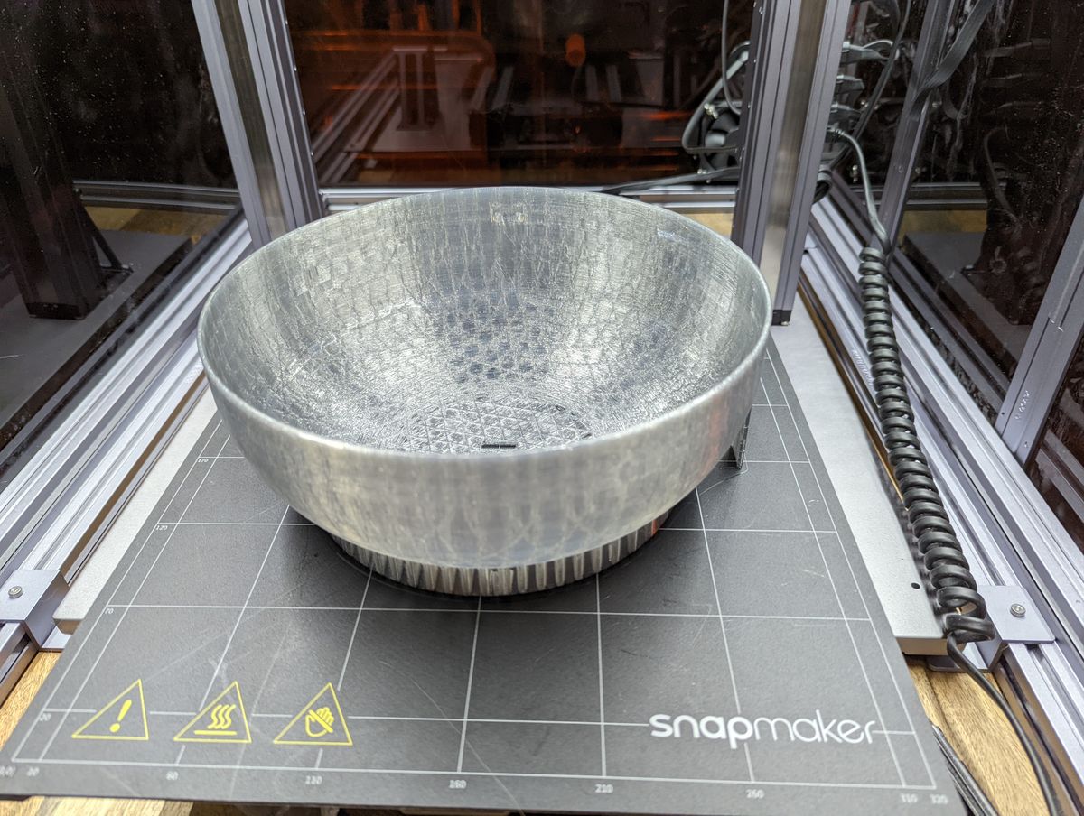
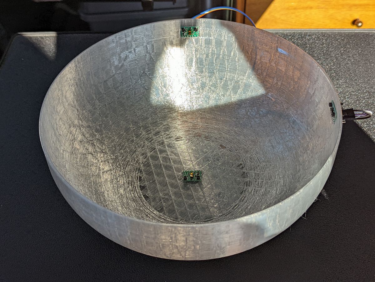
Thus, by waving one's hand around in the bowl, its position can measured and plotted based on the distance to each of the TOF sensors.
Bonus: Scraping Past HTMAA Websites & Machine Learning
The real intent behind what I wanted to visualize was traversing the latent space of a trained GAN model. Latent space interpolation is a relatively common "AI visual art" now, but I wanted to move beyond static, pre-generated visuals to live-generated visuals. Olivia and I had previously implemented a near-realtime GAN as the capstone project for 6.869 Advances in Computer Vision taught by Prof. Phillip Isola.I wanted to train a GAN on PCBs of past years to get a "deep PCB dreamer". So, I wrote a Scrapy Spider and ran it overnight on every past HTMAA website that has existed (17 years worth!), conveniently all subtrees of the https://fab.cba.mit.edu/classes/863. syntax, downloading every image - all 88,405 of them. They were then ran through a processor that thresholded based on the percentage of black pixels, filtering down to 5,045 images. Lastly, I hand-filtered liberally down to 3,529 images, which was sufficient for use in StyleGAN with adaptive discriminator augmentation.
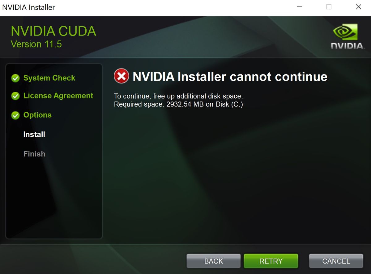
I then trained StyleGAN, using both the StyleGAN2 and StyleGAN3 regimes, and output several test videos of interpolation loops. There are a lot of details about this process that are probably unrelated, but suffice to say, I ran out of time (owing to limited available computation power due to other models I was training for research) and ended up with relatively half-baked models. The latent space interpolation z- values were then manually fed from TD, which itself was pulling values from the sensor readings. However, the kicker here ended up being that when it came to deploying the model, the laptop I was using ran out of space on its main partition to install CUDA.