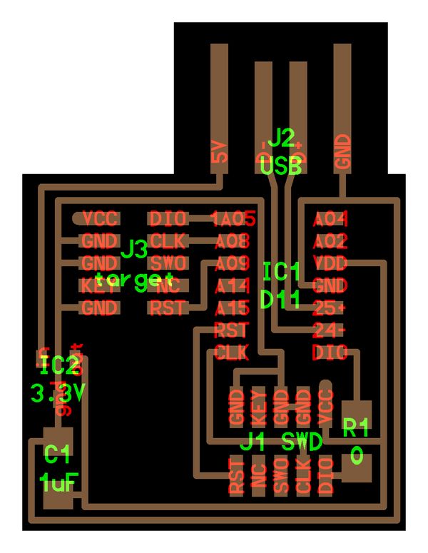
This was a fully SMT board consisting of an IC, two headers, a voltage regulator, a cap, and a resistor.
In discussion with Anthony, I discovered that this board, built out of $2 to $3 in parts, effectively does the same job as the bigger ATMEL-ICE programmer that he has which costs $176!
The price differential (and cost savings) came as a pretty big shock for me, and really speaks to how FabLab-style fabrication methods can be impactful in less economically developed countries.
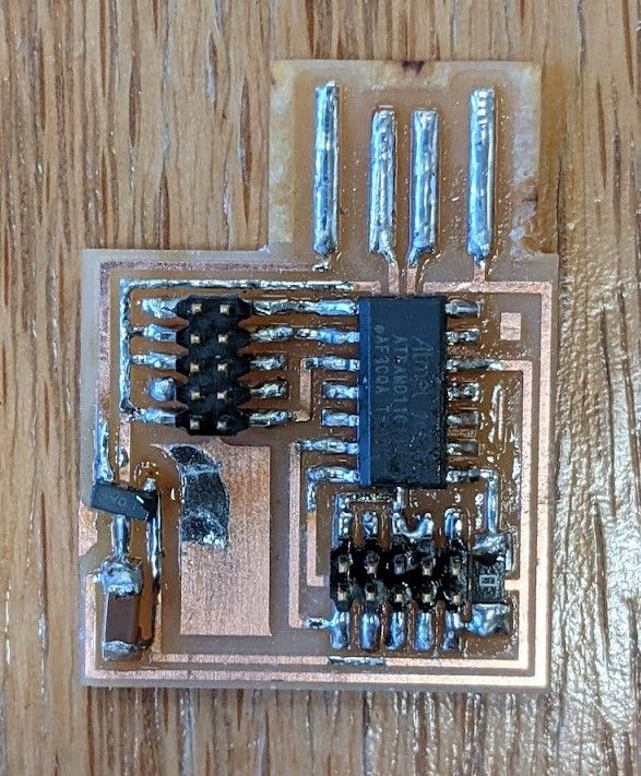
In fabrication, the board was fairly straightforward to mill and mount, although it had been years since I had done any SMT soldering (and truly did a terrible job of it before).
Two valuable pieces of advice provided by Anthony - ensuring that both the contact and legs are heated, and leaving the iron in the solder for a few more seconds to let it flow before removing - really seem to have helped me this time.
I had a minor issue where I attached the wrong voltage regulator, and in removing it, partially removed the trace.
A little bit of janky positioning of the correct voltage regulator and hacky soldering (behind the legs/chip) resolved the issue, though!
To mitigate just-barely shaking hands while placing components, he commented on it being caused by something relating to potassium, and suggested good rest as well as a full breakfast; I suppose coffee alone doesn't count!
With the hardware resolved, Anthony helped test and load the bootloader on my board, which worked splendidly!
Finally, the traces for the USB interface were raised with solder, and a backing layer of black vinyl was attached around the rear and trimmed-to-shape with a blade in order to give it more thickness to fit into a USB port.
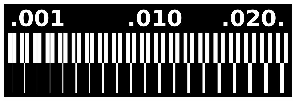
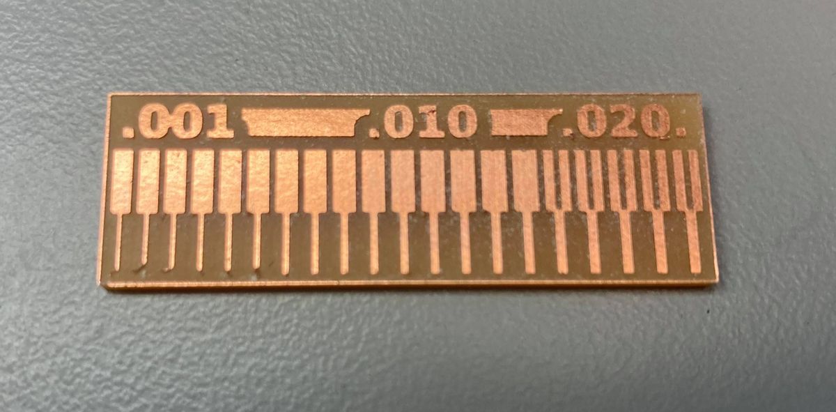
PCB Mill Characterization
As a group, we characterized the two mills in the EDS Lab, with the Roland PCB mill producing the better of it and the Othermill's results (albeit with the tradeoff of more wear on the 1/64 endmill) compared to the Othermill.
We used a standardized test design to test the ability of the PCB mill to both cut thin lines and leave thin lines during milling, as well as to check for its burring.