I chose to use KiCad for this week mostly knowing that Eagle was going the way of the cloud, a la Adobe-style, so although I wanted to learn Eagle, I knew it was better not to set myself up for future disappointment.
The board I chose to "re-design" was the ATSAMD11C hello.D11C.echo board.
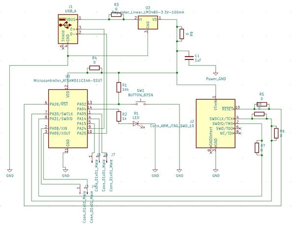
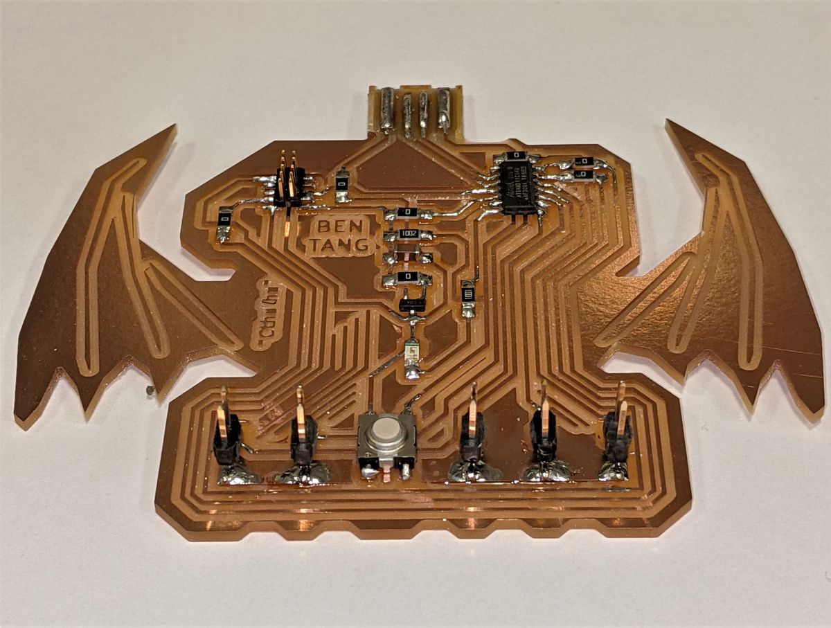
In addition to adding the required LED (with current-limiting resistor) and button (with pull-down resistor), I broke out all of the remaining GPIO pins on the ATSAMD11C IC into separate 0.1" header pins for flexibility.
In the process of drawing the schematics, I realized that the multitude of header pins lent itself to a very natural animal design, an octopus.
I decided to pay homage with that to a cult classic - Cthulhu - as an evolution of the octopus idea.
I was pretty proud that my schematic only required one redesign to fix a major design error (that I knew of at the time, however, see below).
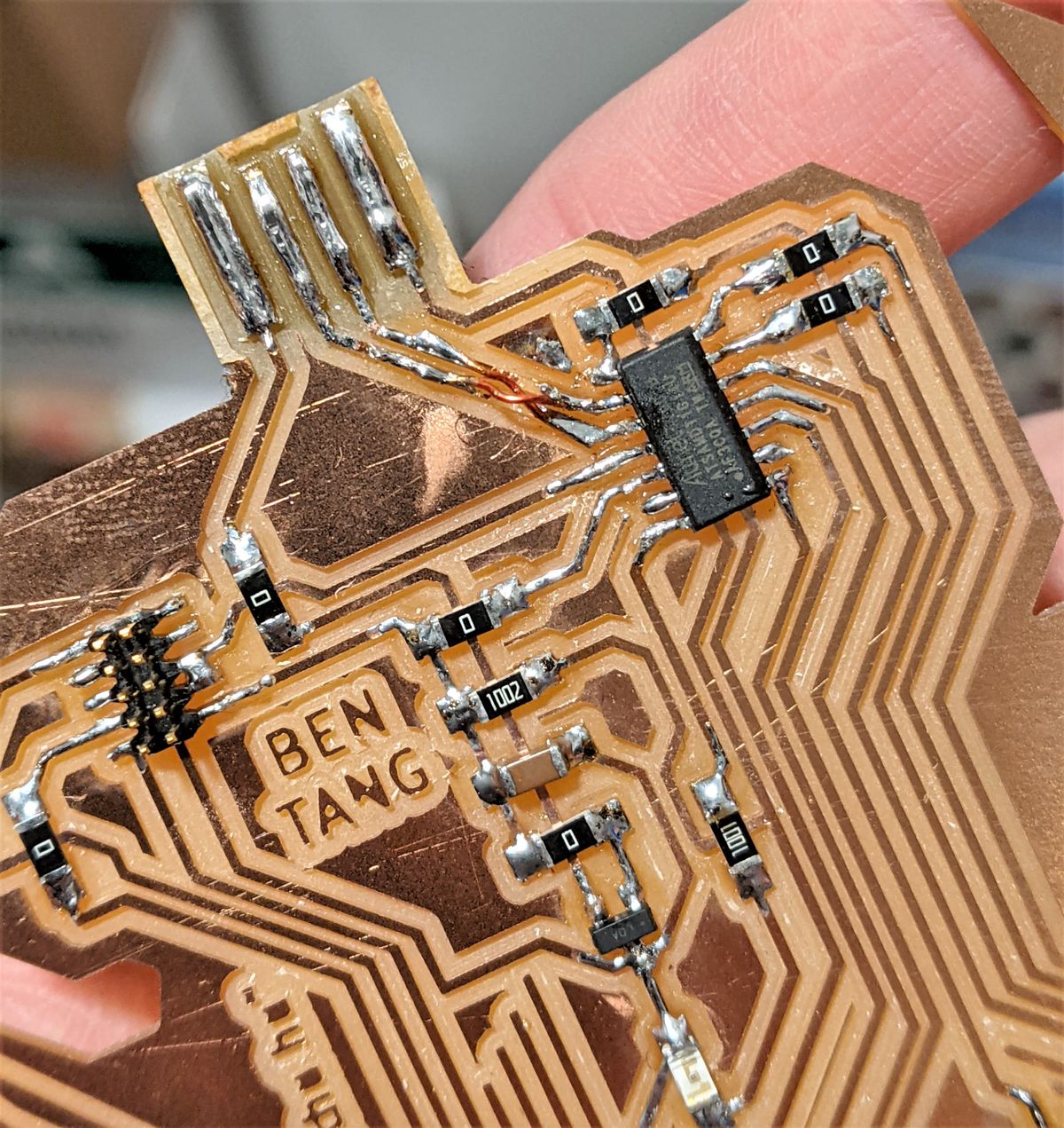
This schematic is hardly a piece of work I'm proud of, and although I incorporated Anthony's best practice of how to designate jumper 0Ω resistors,
I recognize that I need to do a better job of using labels to tidy up my routing and labeling headers more explicitly.
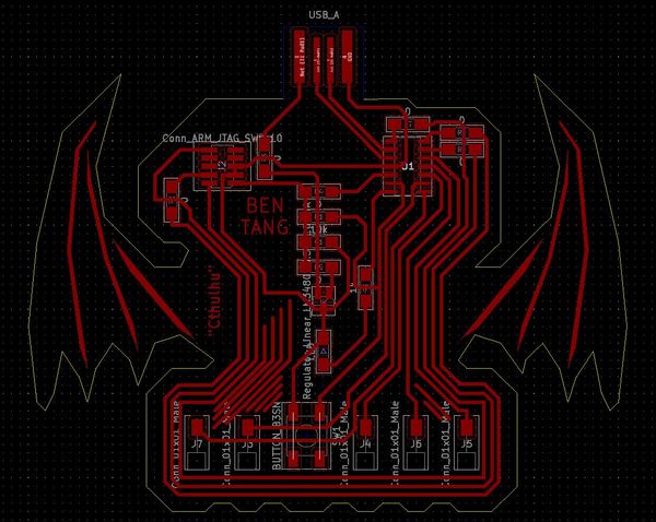
The need to tack on Cthulhu's wings gave me the excuse to try laying out and designing Cthulhu (using a sort of cartoon/8-bit look as a reference) in KiCad,
which is whole different experience to normal vector-based art as you have to take into consideration where the remaining "islands" of traces will remain after the milling.
Unfortunately, as part of the complicated PCB routing (using only a single-sided board with no vias), the sheer number of jumper 0Ω resistors made Cthulhu look... very not-Cthulhu.
Oh well, it looks like some kind of cute demon imp now, I guess. Works for me \o/
PCB Milling & Components
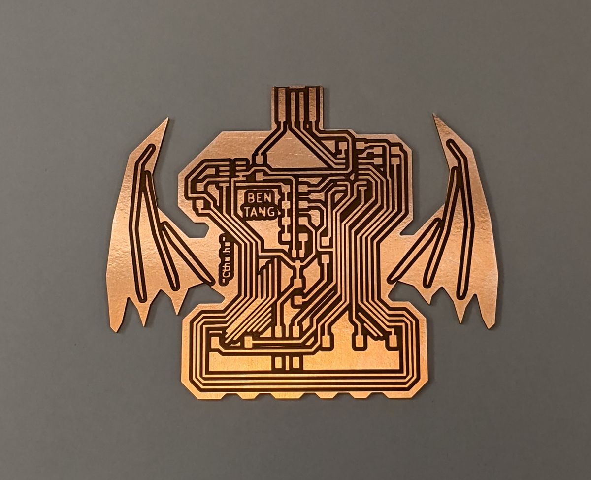
Furthermore, in hindsight, the text was definitely too small to mill out (I didn't check this, and assumed KiCad would scream at me if it was since I had set global toolsize minimums - I was wrong),
and there were a -lot- of islands! Like I said, very not-Cthulhu, but still kinda cute!
A small perk to this design (unintentionally so) was that the tips of the wings prevent me from directly plugging it into a computer's USB port,
and instead requires the use of a USB-A extension cable.
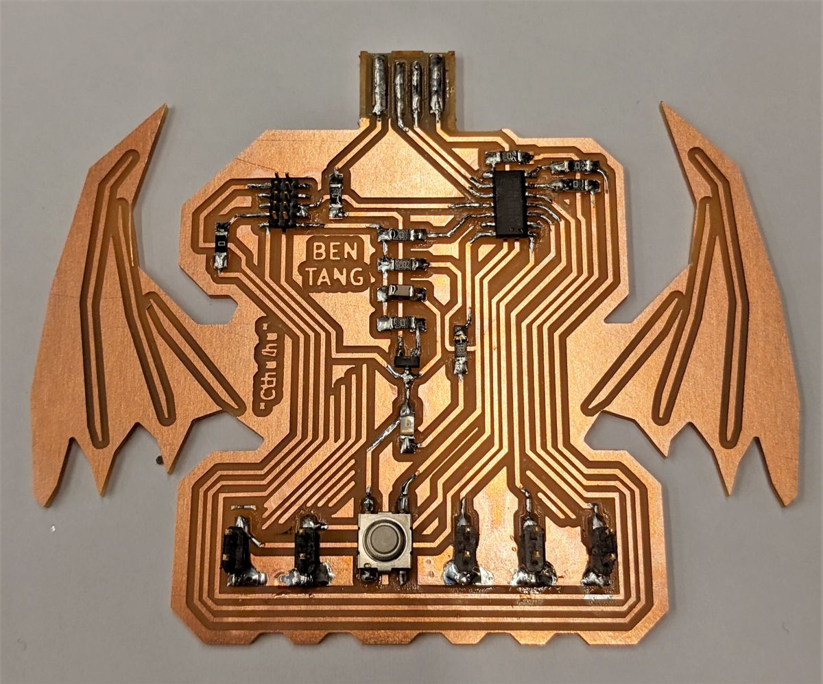
My SMT soldering has certainly improved by this point, and I was able to bang out the components in a matter of a couple of hours or so -
the majority of that time spent looking for components in EDS, figuring out (plus double and triple checking!) which pads were for which components,
the orientation of the ATSAMD11C IC, and how to best trim a strip of 1x1 and 2x2 headers into single 1x1 or a pair of 1x2 headers for my breakout pins.
Indeed, with the number of components and the negative space not quite what I imagined it would look like, it looks like a cute demon-thingie more than Cthulu now.
Gratefully, my SMD soldering skills were up to par (minus the bit where I burned a hole in my finger because I forgot that hot header leg = hot header pin), and there was no soldering-related rework required.
Unfortunately, in my schematic, I had swapped D+ and D- from the USB to the ATSAMD11C, and I had to cut the traces and jumper across to the correct pins with wire.
Thankfully, this fix too went relatively smoothly. With tinned USB headers and a vinyl shim on the back, my board was ready to go!
Programming, Testing & Characterization
Unfortunately, I wish I could say that programming and testing went equally as smoothly.
Between a lack of clear instructions and conflicting documentation available (and an overpopular Anthony!), programming and debugging the board to function for the group assignment took on the order of three to four hours after the board was fabricated.
Later parroting that same information to another person via WhatsApp took them under an hour from the same point where I started, and the supporting documentation/instructions for the course could certainly be improved here.
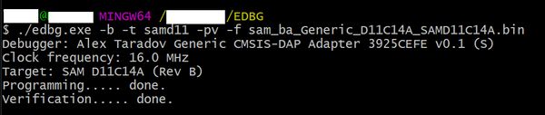
After finally installing Atmel/Microchip Studio, Arduino IDE, and the EDBG, it was off to programming my board.
Although my Week 3 programmer board appeared to program my new board fine, it refused to be detected as a COM serial port, necessitating TA Anthony to reflash the bootloader with his ATMEL-ICE, at which point it worked.
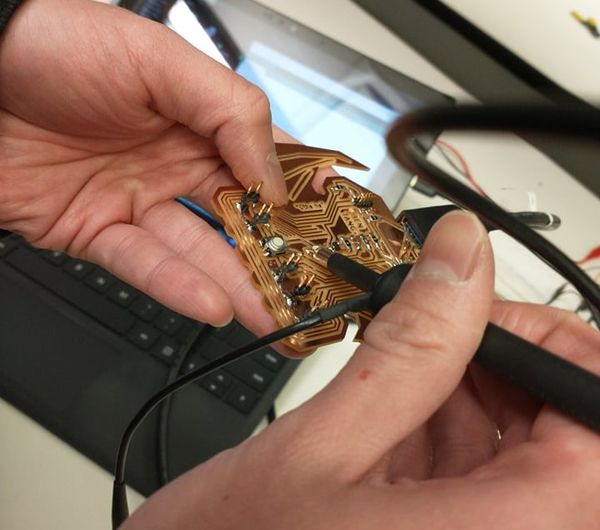
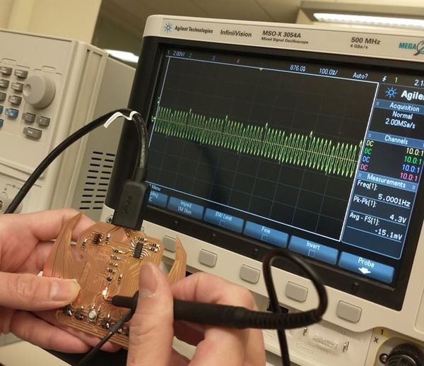
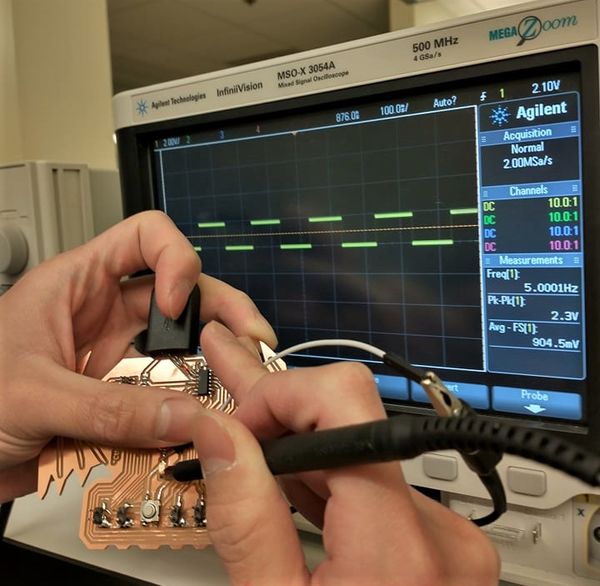
Finally, with Anthony's help, we wrote a quick Arduino C script that would blink the LED with a simple set of instructions - ON, WAIT 100MS, OFF, WAIT 100MS - repeatedly.
By connecting the oscilloscope to measure between the 3.3V in of the LED and ground, we were able to observe an oscillating plot of high and low voltages,
which matched our expected frequency of approximately 5Hz calculated from the single ON-OFF cycle of 200ms.
This thus satisfies our group's assignment for the week to observe the operation of a microcontroller circuit board.