Week 9: Input Devices

Concept

I have a photography lightbox that I had been interested in building a turntable for, which would allow me to film short clips of a subject rotating in a fairly professional manner. My plan was to combine Input and Output weeks into a turntable with capacitive touch buttons to control speed. Input week would thus be a fairly straightforward implementation of a step response control. Why step response rather than a plain button? Pedagogical reasons, largely - I wanted to learn how they worked and how to implement them. There really wasn't much of a need to implement this functionality with step response controls!

Board Design

alttext alttext
I worked ahead here, discussing with Anthony what would be needed on my board for motor control in Output week. The design was based off of a SAMD21E, which had more memory for the code I was going to need to write. I used a single 2x2 header for two step response buttons using digital out pins on the SAMD21E and analog in pins with both pullup and pulldown resistors. Another 2x2 header was used for the motor control, to be connected to Zach's DRV8436 breakout board for the stepper driver. As is customary on my boards, I implemented a power LED.
alttext
For development, I simply cut two copper squares for one button's pins, and taped breakout cables to them.

Code

The Arduino and Processing code for development was largely referenced from the Adrianino input boards. 
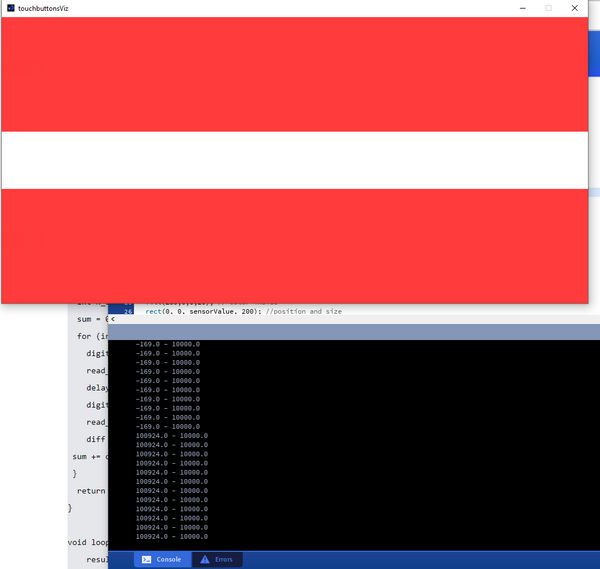
I modified them slightly to take into account handing off data for two different touch buttons, but in development left the second button as a flat returned value of 10000.

long result;
int analog_pin = 2;
int tx_pin = 1;
void setup() {
pinMode(tx_pin,OUTPUT);
Serial.begin(115200);
}

long tx_rx(){
  int read_high;
  int read_low;
  int diff;
  long int sum;
  int N_samples = 100;
  sum = 0;
  for (int i = 0; i < N_samples; i++){
    digitalWrite(tx_pin,HIGH);
    read_high = analogRead(analog_pin);
    delayMicroseconds(100);
    digitalWrite(tx_pin,LOW);
    read_low = analogRead(analog_pin);
    diff = read_high - read_low;
 sum += diff;
 }
  return sum;
}

void loop() {
    result = tx_rx();
    Serial.print(result);
    Serial.print(",");
    Serial.println(10000);
    delay(100);
}

import processing.serial.*;

float sensorValue; //variable for the serial data
float sensorValue2;
Serial myPort;
String teststring;

void setup() {  //as dynamic/setup function called initially, only once
  size(1024, 500);// is the window (1024=sensor max. value)
  //replace the port String with the port where your Arduino is connected
  //myPort = new Serial(this, "/dev/tty.wchusbserial1450", 115200);
  myPort = new Serial(this, "COM6", 115200); // serial port
  background(255);  //set background white
  
}

void draw() {  //draw function loops 
  
  noStroke(); // outline
  fill(255,0,0,20); // color inside
  rect(0, 0, sensorValue, 200); //position and size
  rect(0, 300, sensorValue, 200); //position and size
  
  fill(255,70);
  rect(sensorValue, 0, width-sensorValue, 200);
  rect(sensorValue, 300, width-sensorValue, 200);
  
  //println(teststring);
  println(sensorValue + " - " + sensorValue2);
  fill(0,0,0);// these are the colors inside
  text(sensorValue + " " , sensorValue, 100);
  text(sensorValue + " " , sensorValue, 400);
  textSize(32);
}

void serialEvent(Serial myPort) { // sketch read the serial data
  String inString = myPort.readStringUntil('\n');
  teststring = inString;
  if (inString != null) {
    inString = trim(inString);
    float[] values = float(split(inString, ","));
    if (values.length >=1) {
      sensorValue = values[0]; //first value in the list
      sensorValue2 = values[1];
    }
  }
}

Results

The Processing code generated a red bar with an intensity corresponding to the input values.
alttext
Thus, I was able to verify that my board, the step response pads, and the code were working.