This week, I made an ESP32 developer board that allows for attachment of an Adafruit PM2.5 air particle sensor. Sensor data from the PM2.5 is received on the ESP32 which acts as a webserver and streams the received environmental particle data to a static IP address where it can be read out by a client. Here, I use my laptop on the same WiFi network as the ESP32 to display the sensor data in my web browser.
2. PCB Design
3. PCB Milling and Stuffing
4. Programming
4.1 Step 1: Testing ESP32 Wi-Fi Connectivity
4.2 Step 2: Read Out PM2.5 Sensor Data
4.3 Step 3: Send Sensor Data to Client Browser
Intro to ESP32 and PM2.5 Dust Sensor
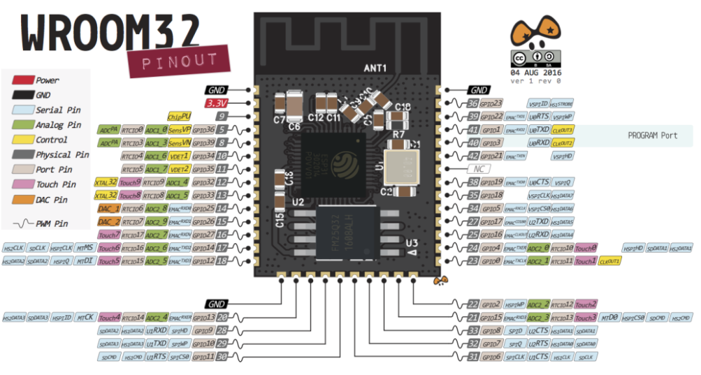
The ESP is a WiFi- and Bluetooth-enabled board featuring an array of peripherals such ADCs, and DACs, as well as UART, SPI and I2C interfaces. A good reference for pin functionality, restrictions and features can be found here. The variation of ESP32 used here is called ESP32-WROOM and developer breakout boards are readily commercially available. These developer boards have the basic functionality described below already implemented as as well as GPIO pins made accessible. Here, I will manufacture my own basic version of a ESP32 developer board with a single pin header that allows for connection of a PM2.5 sensor.
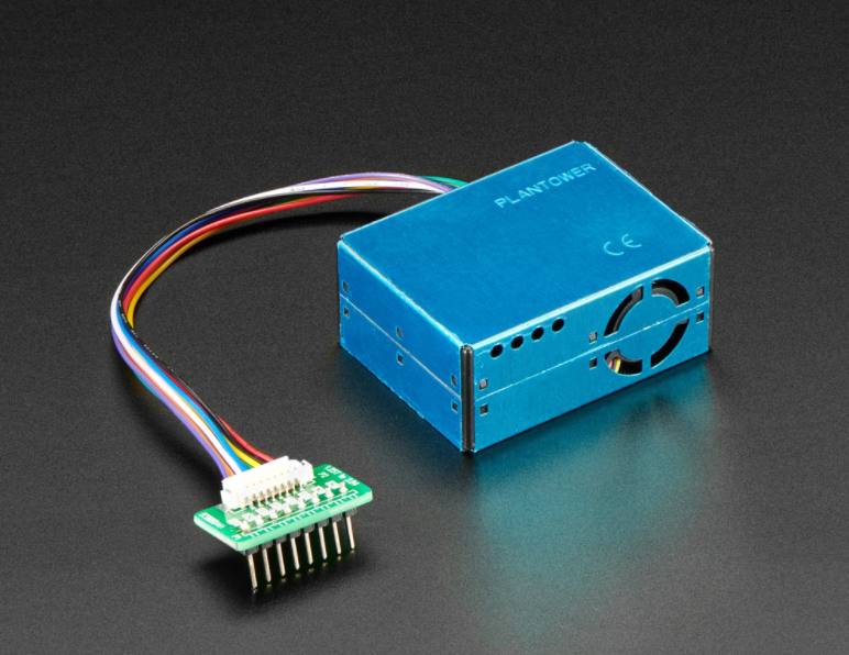
The Adafruit PM2.5 air quality sensor is a particle sensor that uses light scattering in order to determine particle counts in the surrounding air. In short, the PM2.5 features a fan that sucks air into its cavity where any suspended particles are struck by and scatter a light beam. The scattering cross-sections detected on a photosensor can be analyzed to bin the scattering sources into different sizes. PM2.5 referes to particles that are 2.5 um or smaller in size and is one of the results that the PM2.5 provides. Most relevant for my application is the concentration of particles larger than 0.5 um, as this is the measure used in the qualification of air quality in cleanrooms.
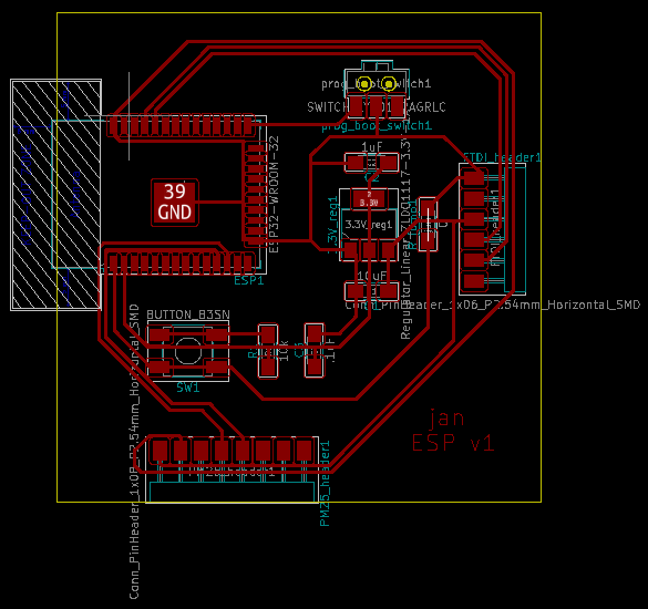
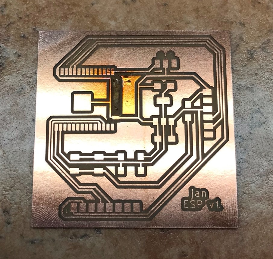
PCB Design
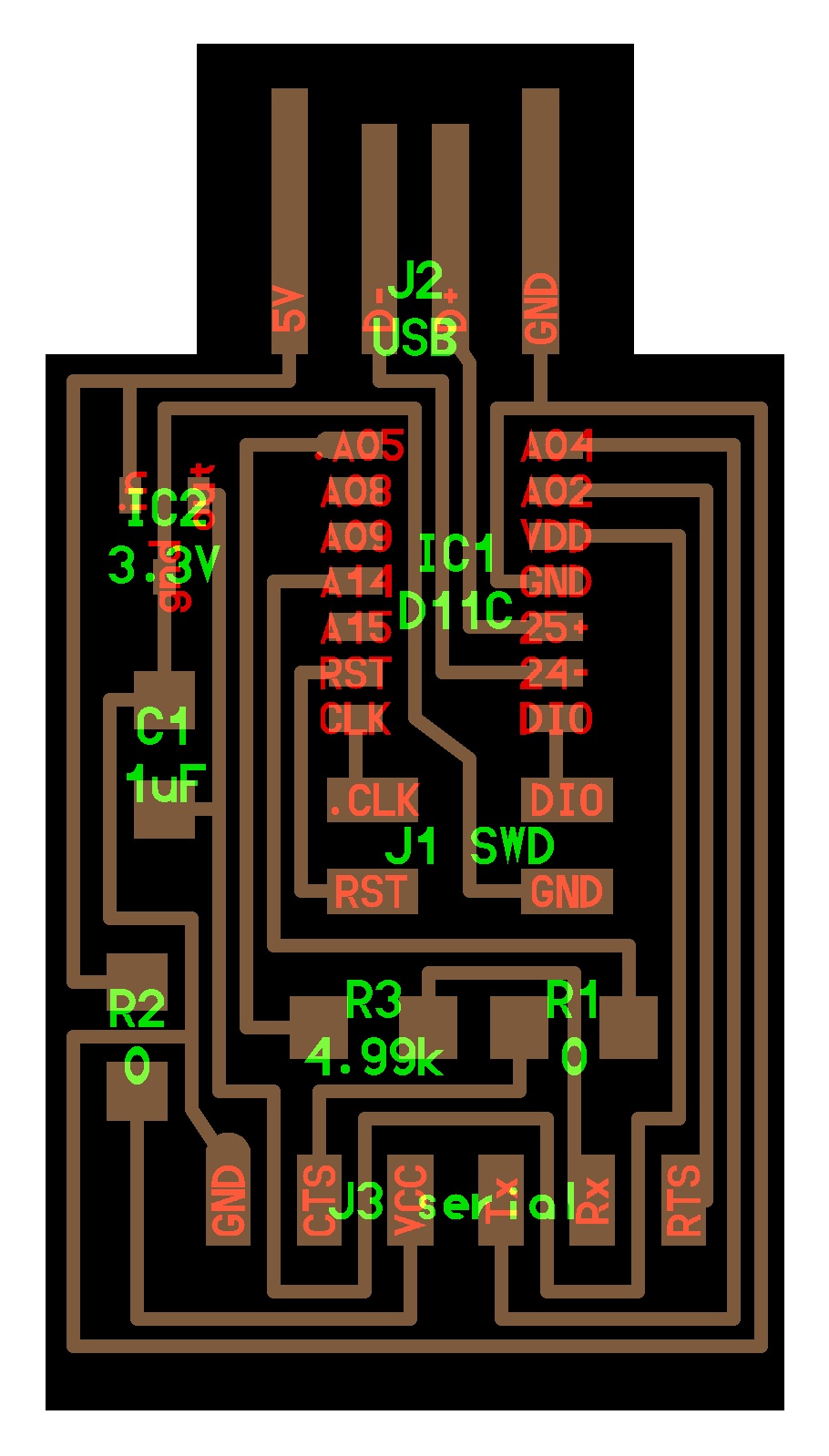
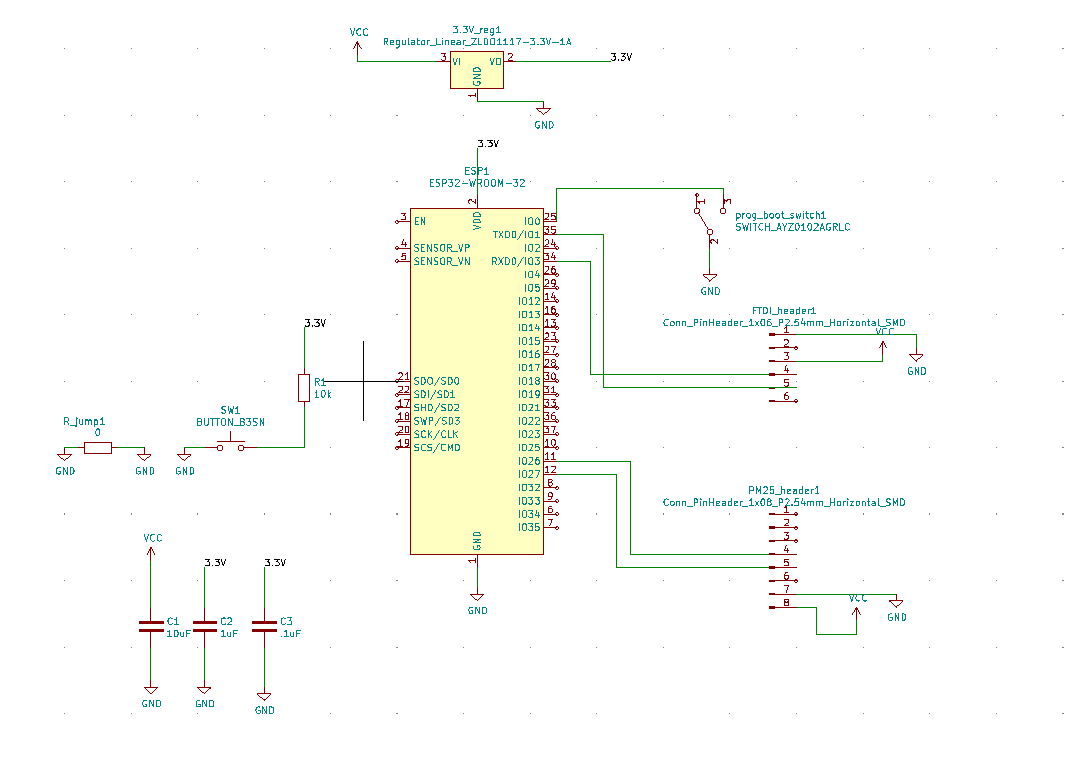
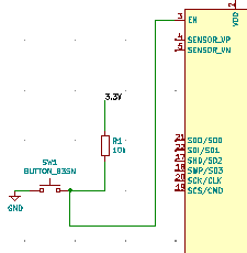
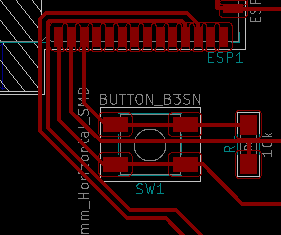
For the ESP32, I started from Neil's helloworld ESP32 WROOM developer board. Note that I made a mistake in the schematics of this board (which I noticed only after stuffing and fixed with a jumper cable): The top contacts of the push button need to be connected to pin EN on the ESP32. In order to read out sensor data from the PM2.5, I added a pin header, as seen at the bottom of the board layout. The schematics I used to mill my board are shown on the left-hand side below, as well as the board layout on the right-hand side. The ESP32 developer board allows for programming of the ESP32 WROOM with the following features to be noted:
- The pin header seen on the right-hand side of the board layout allows for connection of a serial programming header. This can either be done through a USB-to-serial board such as this one or a commercial USB-to-serial cable by FTDI .
- The switch seen towards the top of the board layout connected to GPIO pin 0. GPIO0 is a so-called strapping pin and is needed to switch between download and operating mode of the ESP32. The pin is internally pulled up, which puts the board in operating mode. Hence, when the switch is in the right-hand side position, that is, no connection is made to GPIO0, the pin is HIGH and the board in operating mode. When the switch is in the left-hand side position GPIO0 is pulled LOW and the ESP32 is in download mode, that is, ready to receive new code.
- The push button is used to reset the board when switching between download and operate mode of the ESP32. It is supposed to be connected to pin EN on the ESP32 (missing in my schematic as mentioned above). This is the ENABLE pin on the ESP32 that enables the board's internal 3.3V voltage supply. If this pin is pulled LOW, the power supply is interrupted, hence pushing the button allows for resetting of the ESP32.
PCB Milling and Stuffing
I milled the above shown PCB design on the Roland SRM-20 PCB mill. Unfortunately, in a first version of my design I pushed the design rules a little too close to their limits by setting clearance to 15 mils and track width to 12 mils. as can be seen below this caused some tracks to not get milled.
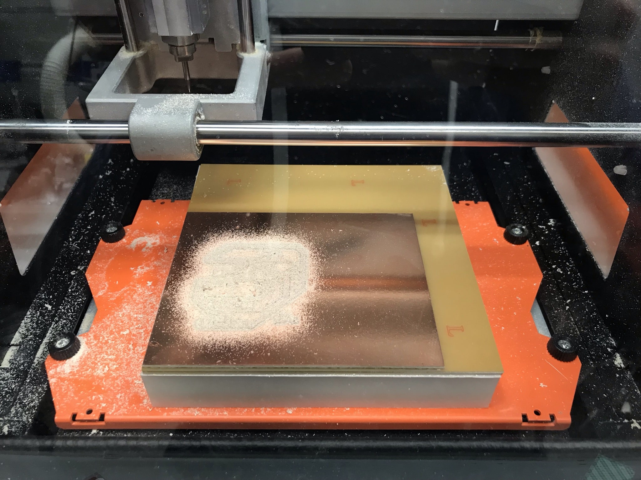
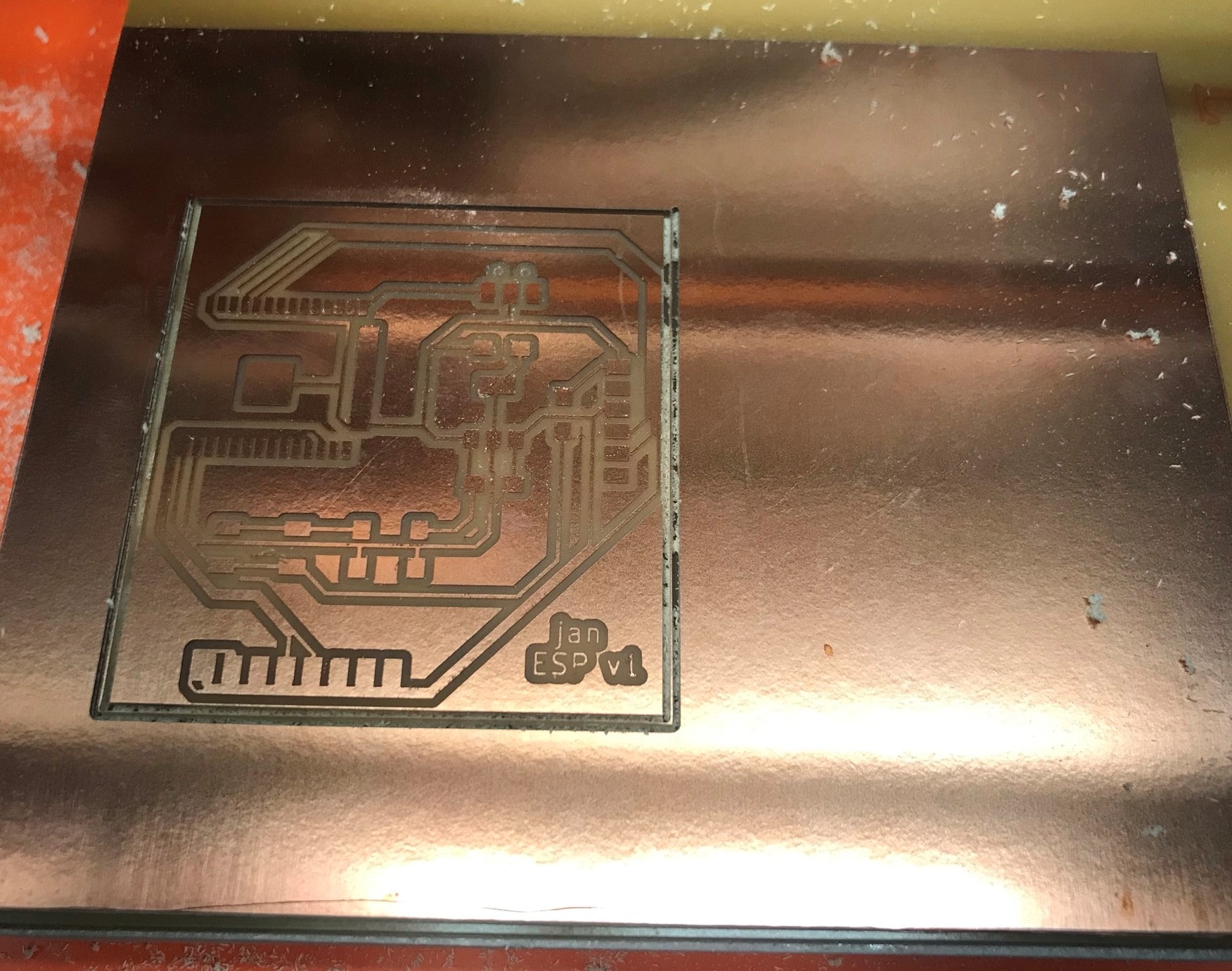
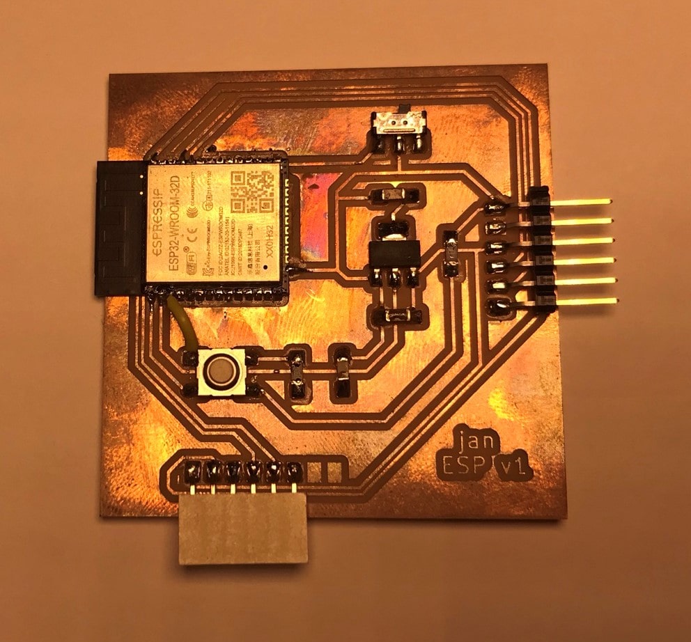
I thus adjusted clearance to 17 mils and track width to 14 mils. This yielded all tracks being milled cleanly. Unfortunately, the footprint for the ESP32 provided in the fab academy KiCad library did not allow for the pads on the right-hand side of the ESP32 to be milled at all. I thus separated the lowest pad, which I need for a GND connection off with an exactor knife, as shown in the image on the left. Luckily, I don't need any of the other pads. Nonetheless, I did not want to leave the pads connected like this, as the ESP32 uses some pins to send and receive signals during booting, and in the current state all pads would be shorted together. I thus used a heat gun to peel off the copper film for the entire right-hand side connected pads, shown below in the image on the right.
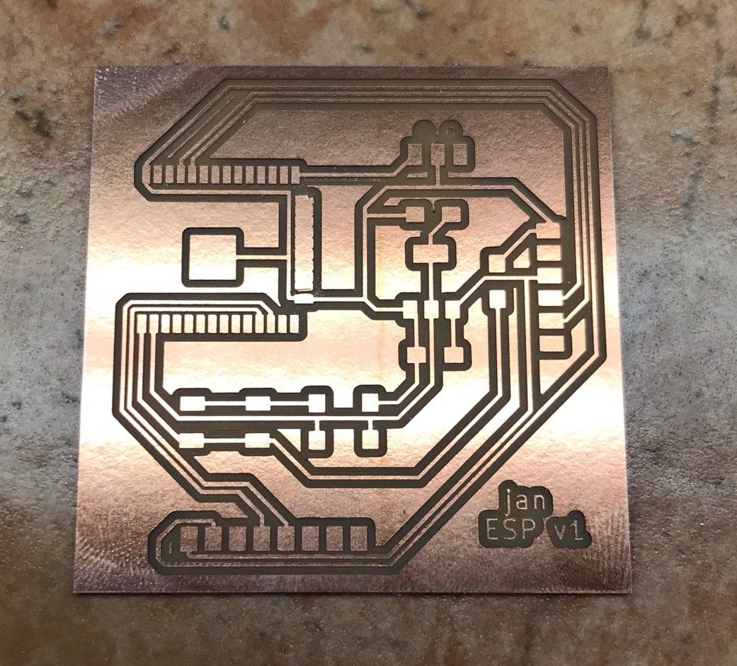
Finally, I stuffed my board with all the required components and a added a jumper wire to the missing button-to-EN connection mentioned above. For convenience, I show below the fixed schematic and board layout making the connection I added via jumper wire here.
Programming
Step 1: Testing ESP32 Wi-Fi Connectivity
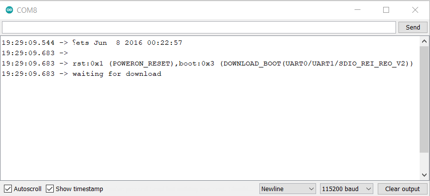
In order to test Wi-Fi connectivity of the ESP32 I used Neil's helloworld example of setting up the ESP32 as a webserver. To connect to WiFi, the WiFi's name and password to be connected to need to be inserted. Then, to be able to use ESP family boards in my Arduino IDE, I pasted the following link under File -> Preferences -> Additional Board Manager URLs (separated by comma from any URLs already in this field): https://raw.githubusercontent.com/espressif/arduino-esp32/gh-pages/package_esp32_index.json. In order to load code onto the ESP32, I used an FTDI USB-to-serial cable. Further, in the following order, I set the switch to connect to GND to set the ESP32 into download mode, as desribed above and then pushed the reset button. This triggers the message shown below to be displayed on the serial monitor. Note that baud rate has to be set to 115200 for the message to be displayed in legible format.
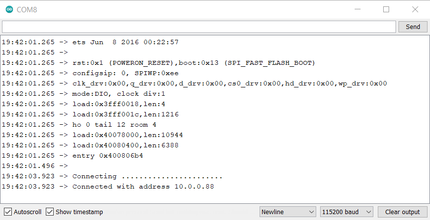
After having flashed the code, the ESP32 is set back into operating mode by setting the switch back into disconnect position and pushing the reset button a second time. This triggers the following message to be displayed in the serial monitor.
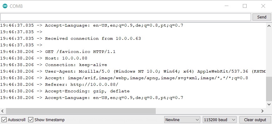
Finally, the connection can be verified by accessing the IP address displayed above from a web client. Here, I use a browser window on my laptop connected to the same Wi-Fi. Upon entering the IP address into the browser search bar and hitting enter, the ESP32 confirms on the serial monitor that a request from my computer was received, as shown below.
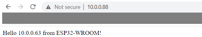
In my browser window, the following messsage is received, as intended.
Step 2: Read Out PM2.5 Sensor Data
In order to read out sensor data from the PM2.5, Adafruit conveneniently provides a library which can be found here as well as example Arduino code found here. In principle, the sensor can be read out with either hardware serial or software serial. Since the ESP32 supports mapping of its UART2 peripheral to any pin, I followed instructions I found here and here. After installing the busIO library shown below, I managed to connect to the PM2.5. However, while both examples seem very similar and straightforward, I was unable to receive any sensor data from the PM2.5 using this approach.
I thus implemented a software serial connection. For this to work I had to install the Sotwareserial library for ESP family for which documentation can be found here.
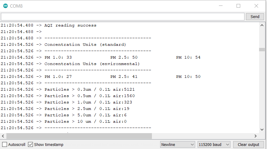
With this approach I finally managed to print sensor data to the serial monitor binned into different categories as shown below.
The code I used to achieve this is pasted below.
          #include "Adafruit_PM25AQI.h" //Adafruit library for PM2.5 air quality sensor

          // Set up hardware serial on ESP32
          # define RX 26 // connected to TX on PM2.5
          # define TX 27 // unused, connected to RX on PM2.5

          // Set up software serial below if hardware serial cannot be used
          // Comment these two lines if using hardware serial
          #include  <SoftwareSerial.h>
          SoftwareSerial pmSerial(26,27); // On my ESP32 IO26 connected to TX on PM2.5

          // Create instance of PM2.5 sensor
          Adafruit_PM25AQI aqi = Adafruit_PM25AQI();

          void setup() {
            // Wait for serial monitor to open
            Serial.begin(115200);
            while (!Serial) delay(10);

            // Set up hardware serial with TX and RX pins as defined above
            // comment if using software serial
            // Serial2.begin(115200, SERIAL_8N1, RX, TX);

            Serial.println("Adafruit PMSA003I Air Quality Sensor");

            // Wait one second for sensor to boot up!
            delay(1000);

            // If using serial, initialize it and set baudrate before starting!
            // Uncomment first for hardware serial, second for software serial
            //Serial2.begin(9600);
            pmSerial.begin(9600);

            // Initialize serial communication with PM2.5
            // Uncomment first "if" for hardware serial, second for software serial
            //if (! aqi.begin_UART(&Serial2)) { // connect to the sensor over hardware serial
            if (! aqi.begin_UART(&pmSerial)) { // connect to the sensor over software serial
              Serial.println("Could not find PM 2.5 sensor!");
              while (1) delay(10);
            }

            Serial.println("PM25 found!");
          }

          void loop() {
            PM25_AQI_Data data;

            if (! aqi.read(&data)) {
              Serial.println("Could not read from AQI");
              delay(500);  // try again in a bit!
              return;
            }
            Serial.println("AQI reading success");

            Serial.println();
            Serial.println(F("---------------------------------------"));
            Serial.println(F("Concentration Units (standard)"));
            Serial.println(F("---------------------------------------"));
            Serial.print(F("PM 1.0: ")); Serial.print(data.pm10_standard);
            Serial.print(F("\t\tPM 2.5: ")); Serial.print(data.pm25_standard);
            Serial.print(F("\t\tPM 10: ")); Serial.println(data.pm100_standard);
            Serial.println(F("Concentration Units (environmental)"));
            Serial.println(F("---------------------------------------"));
            Serial.print(F("PM 1.0: ")); Serial.print(data.pm10_env);
            Serial.print(F("\t\tPM 2.5: ")); Serial.print(data.pm25_env);
            Serial.print(F("\t\tPM 10: ")); Serial.println(data.pm100_env);
            Serial.println(F("---------------------------------------"));
            Serial.print(F("Particles > 0.3um / 0.1L air:")); Serial.println(data.particles_03um);
            Serial.print(F("Particles > 0.5um / 0.1L air:")); Serial.println(data.particles_05um);
            Serial.print(F("Particles > 1.0um / 0.1L air:")); Serial.println(data.particles_10um);
            Serial.print(F("Particles > 2.5um / 0.1L air:")); Serial.println(data.particles_25um);
            Serial.print(F("Particles > 5.0um / 0.1L air:")); Serial.println(data.particles_50um);
            Serial.print(F("Particles > 10 um / 0.1L air:")); Serial.println(data.particles_100um);
            Serial.println(F("---------------------------------------"));


            delay(1000);
          }
Step 3: Send Sensor Data to Client Browser
Finally, I combined the Wifi webserver code with the code I used to read out PM2.5 sensor data. I reduced the sensor readout to the main data point I am interested in, which is concentration of particles larger than 0.5 um, as described above. The PM2.5 outputs the concentration as number of particles / 0.1 liters. For standard cleanroom units this needs to be converted to number of particles / cubic ft which is achieved by multiplying the former with a factor of 283. This value can now be sent to my browser as shown below.

Typically a particle count on the order of 1,000,000 particles larger than 0.5 um per cubic ft is considered office space (cf. reference here). With a particle count of about 300,000 I thus seem to be getting a representative value (however surprising to be on the lower end of that scale given that I would not consider my room a low-dust environment).
The final version of my code is pasted below.
          #include "Adafruit_PM25AQI.h" //Adafruit library for PM2.5 air quality sensor
          #include <WiFi.h> // include Wifi library

          // Set up hardware serial on ESP32
          # define RX 26 // connected to TX on PM2.5
          # define TX 27 // unused, connected to RX on PM2.5

          // Set up software serial below if hardware serial cannot be used
          // Comment these two lines if using hardware serial
          #include <SoftwareSerial.h>
          SoftwareSerial pmSerial(26,27); // On my ESP32 IO26 connected to TX on PM2.5

          // Create instance of PM2.5 sensor
          Adafruit_PM25AQI aqi = Adafruit_PM25AQI();

          // Set access variables for wifi and instantiate
          const char* ssid = "xxxxxxxx";
          const char* password = "xxxxxxxxx";
          WiFiServer server(80);

          void setup() {
            // Wait for serial monitor to open
            Serial.begin(115200);
            while (!Serial) delay(10);

            // Set up hardware serial with TX and RX pins as defined above
            // comment if using software serial
            // Serial2.begin(115200, SERIAL_8N1, RX, TX);

            Serial.println("Adafruit PMSA003I Air Quality Sensor booting...");
            // Wait one second for sensor to boot up!
            delay(1000);

            // If using serial, initialize it and set baudrate before starting!
            // Uncomment first for hardware serial, second for software serial
            // Serial2.begin(9600);
            pmSerial.begin(9600);

            // Initialize serial communication with PM2.5
            // Uncomment first "if" for hardware serial, second for software serial
            // if (! aqi.begin_UART(&Serial2)) { // connect to the sensor over hardware serial
            if (! aqi.begin_UART(&pmSerial)) { // connect to the sensor over software serial
              Serial.println("Could not find PM 2.5 sensor!");
              while (1) delay(10);
            }

            Serial.println("PM2.5 found!");

            //Establish Wifi connection and start server
            printf("\nConnecting to Wifi...");
            WiFi.begin(ssid,password);
            while (WiFi.status() != WL_CONNECTED) {
              delay(100);
              printf(".");
              }
            printf("\nConnected with address %s\n",WiFi.localIP().toString().c_str());
            server.begin();
            delay(3000);

          }

          void loop() {
            PM25_AQI_Data data;

            if (! aqi.read(&data)) {
              Serial.println("Could not read from PM2.5");
              delay(500);  // try again in a bit!
              return;
            }
          //  Serial.println("PM2.5 reading success");

            // PM2.5 computes number of particles larger than 0.5um per 0.1 liter of air
            // -> want number per cubic ft for cleanroom standards
            int part05um_cuft = int(data.particles_05um)*283;

          //  Serial.println(F("---------------------------------------"));
          //  Serial.print(F("There are currently ")); Serial.print(part05um_cuft);
          //  Serial.println(F(" particles larger than 0.5um per cubic ft of air."));
          //  Serial.println(F("---------------------------------------"));
          //  Serial.println();

            delay(1000);

            // Send data to a connected client
            char cold,cnew;
            WiFiClient client = server.available();
            if (client) {
              printf("\nReceived connection from %s\n\n",client.remoteIP().toString().c_str());
              while (client.connected()) {
                if (client.available()) {
                  cnew = client.read();
                  printf("%c",cnew);
                  if ((cold == '\n') && (cnew == '\r')) { // check for blank line at end of request
                    client.printf("HTTP/1.1 200 OK\n");
                    client.printf("Content-type:text/html\n");
                    client.printf("\n");
                    //client.printf("%d\n\n",part05um_cuft);
                    client.printf("There are currently %i particles larger than 0.5um per cubic ft of air.
\n",part05um_cuft);
                    Serial.println("Sent particle count!");
                    client.stop();
                    break;
                    }
                  cold = cnew;
                  }