In this week’s assignment we learned to use the laser cutter to assemble a structure of our choice from joint cardboard pieces. Different kinds of joints can be made depending on the strength of the connection required for one's application. For my assignment I decided to construct a lamp shade that I modeled in Fusion 360 according to the lamp's dimensions. The individual pieces were laser-cut from cardboard before final assembly.
2. CAD modeling in Fusion 360
3. Laser Cutting
4. Lamp Shade Assembly
Introduction to Joint Options
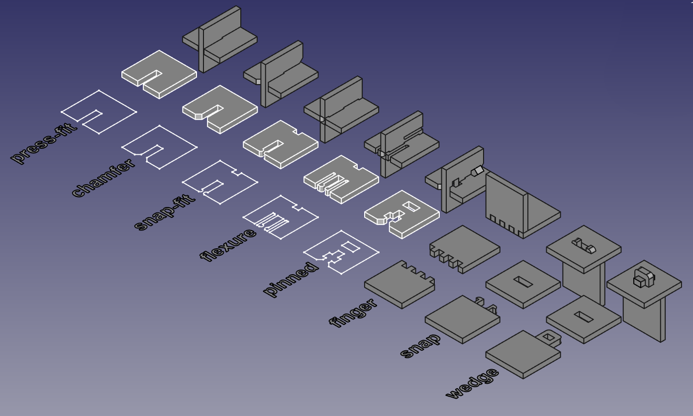
Shown below are the different kind of joints that can be manufactured from simple 2D cuts (image courtesy of Neil Gershenfeld). Various degrees of freedom can be constrained as well as the strength of assembly can be chosen at the cost of complexity depending on the desire application. Here, as shown in the next section, I went with both press-fit connections as well as a wedge connection for different parts of the lamp shade.
CAD modeling in Fusion 360
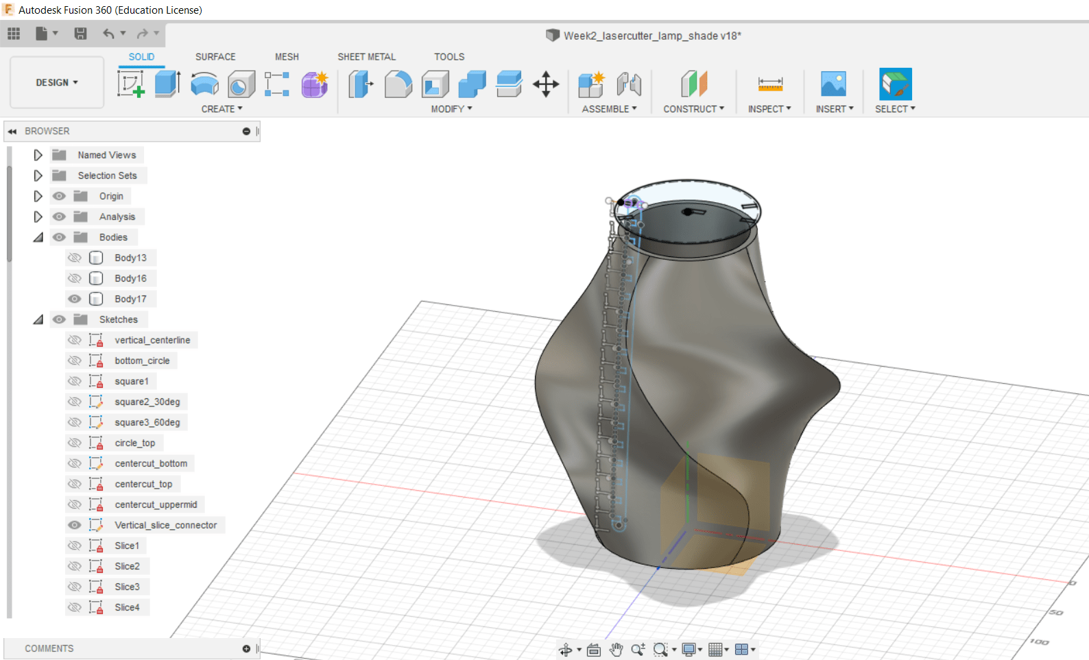
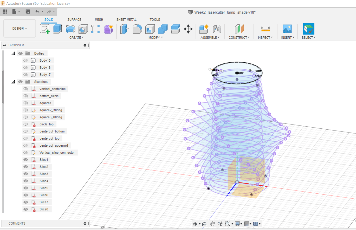
For my lamp shade, I started with creating the outline of the shade by lofting between two circles at the top and bottom and several rotated squares in between to create an aesthetically pleasing outline. I created a second circular loft on the inside where a vertical connector will be attached to the individual pieces. The individual pieces of the shade were created by projecting the lofted outline onto 17 horizontal slices along the loft. They will be connected via a simple press-fit connection and hinged onto the lamp via a “lid” piece that is hinged onto the vertical connector using a wedge connection. The design was created parametrically; in dependence of the lamp shade height the components creating the loft outline change accordingly to maintain a constant aspect ratio as well as a consistent center cut.
Laser Cutting
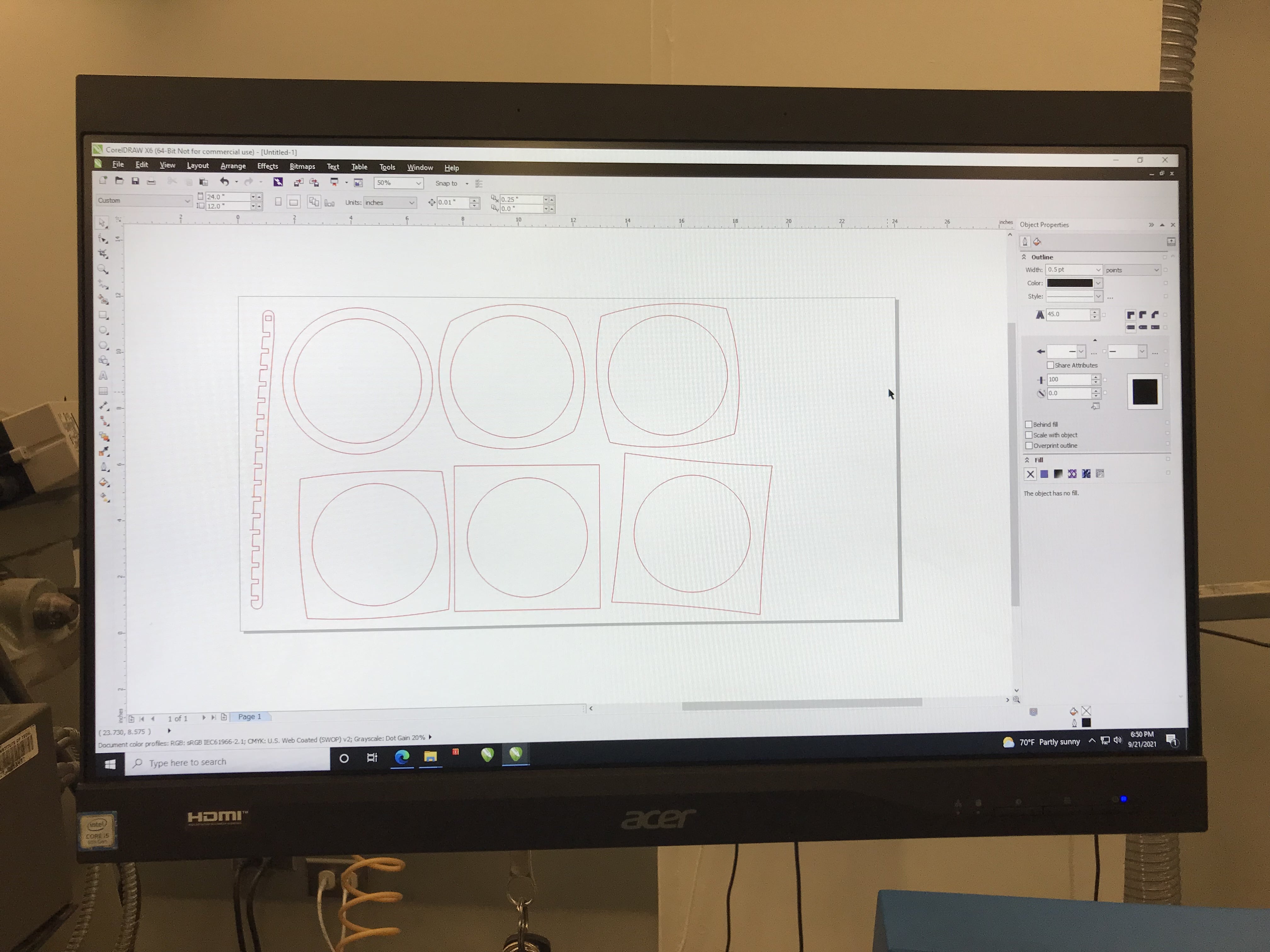
In order to cut the cardboard on the laser cutter, we determined key tool parameters on the machines provided to us in EDS (the machine shop used by the EECS section). We determined the laser kerf to be about 1 mil which will be taken into account in the CAD files for tight joint fits. For the small laser cutter speed needs to be set to 18% to cut through at 100% power. For the large laser cutter speed can be set to 11% at 100% power.
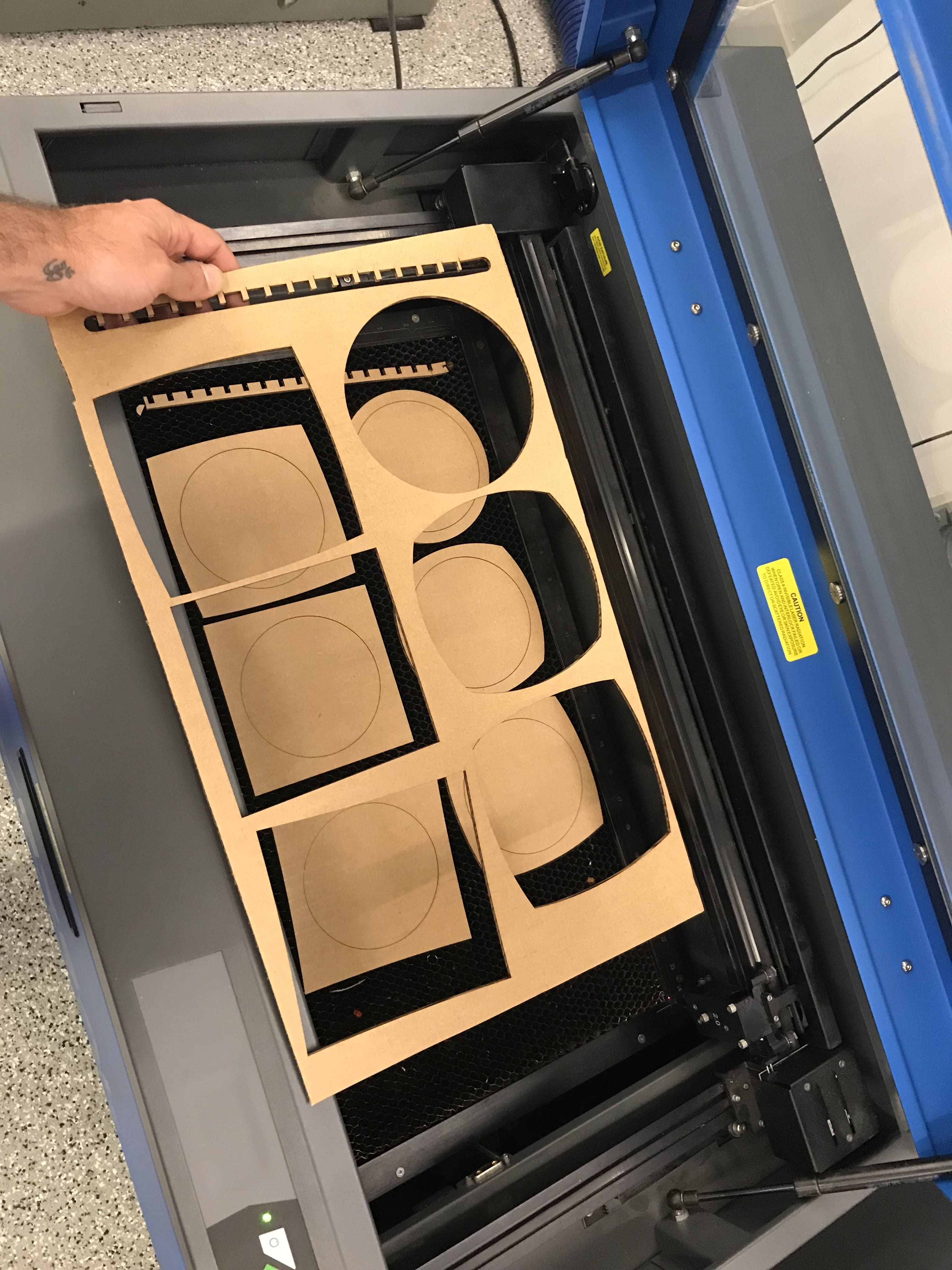
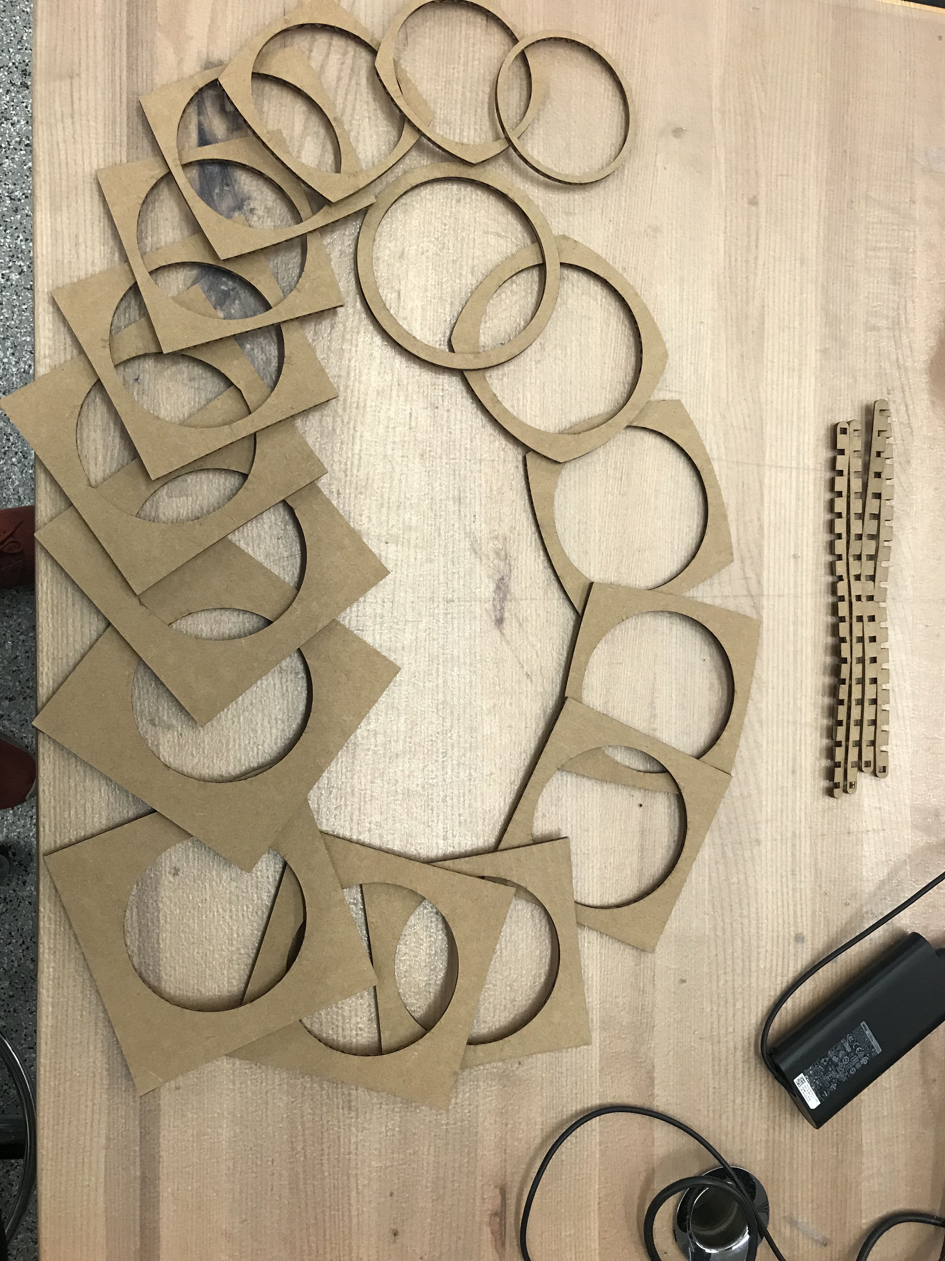
Below shown are exemplary pieces in the laser cutter software as well as the resulting cut pieces. The pieces were finally assembled into the lofted outline described above, hinged into the lid and attached to the top of the lamp.
Lamp Shade Assembly
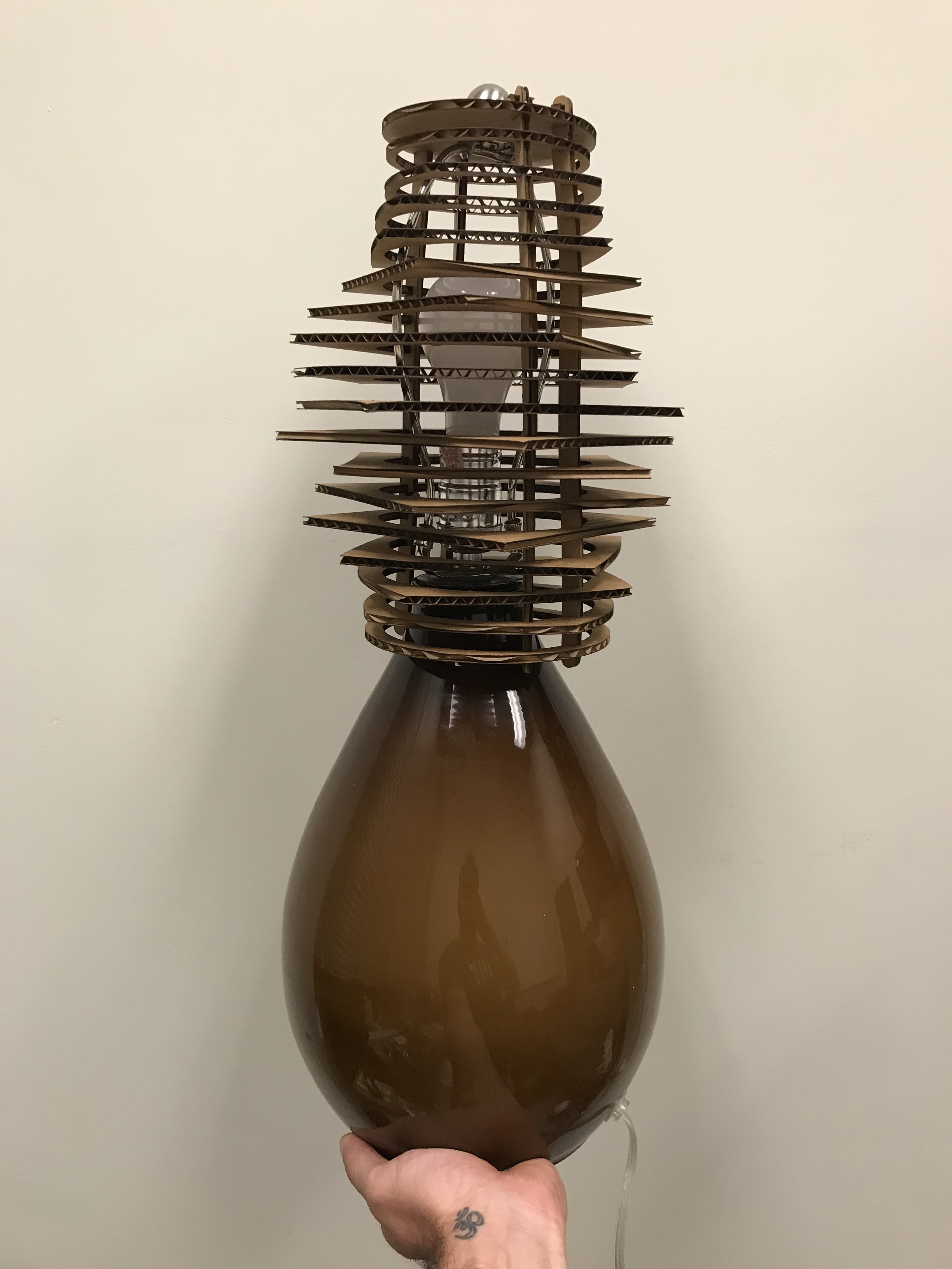
Lamp shade assembly was surprisingly challenging given the compliance of the cardboard on the corners of the connector cut-outs to hinge onto the individual layer pieces. A chamfered connection would have made my life a lot easier.
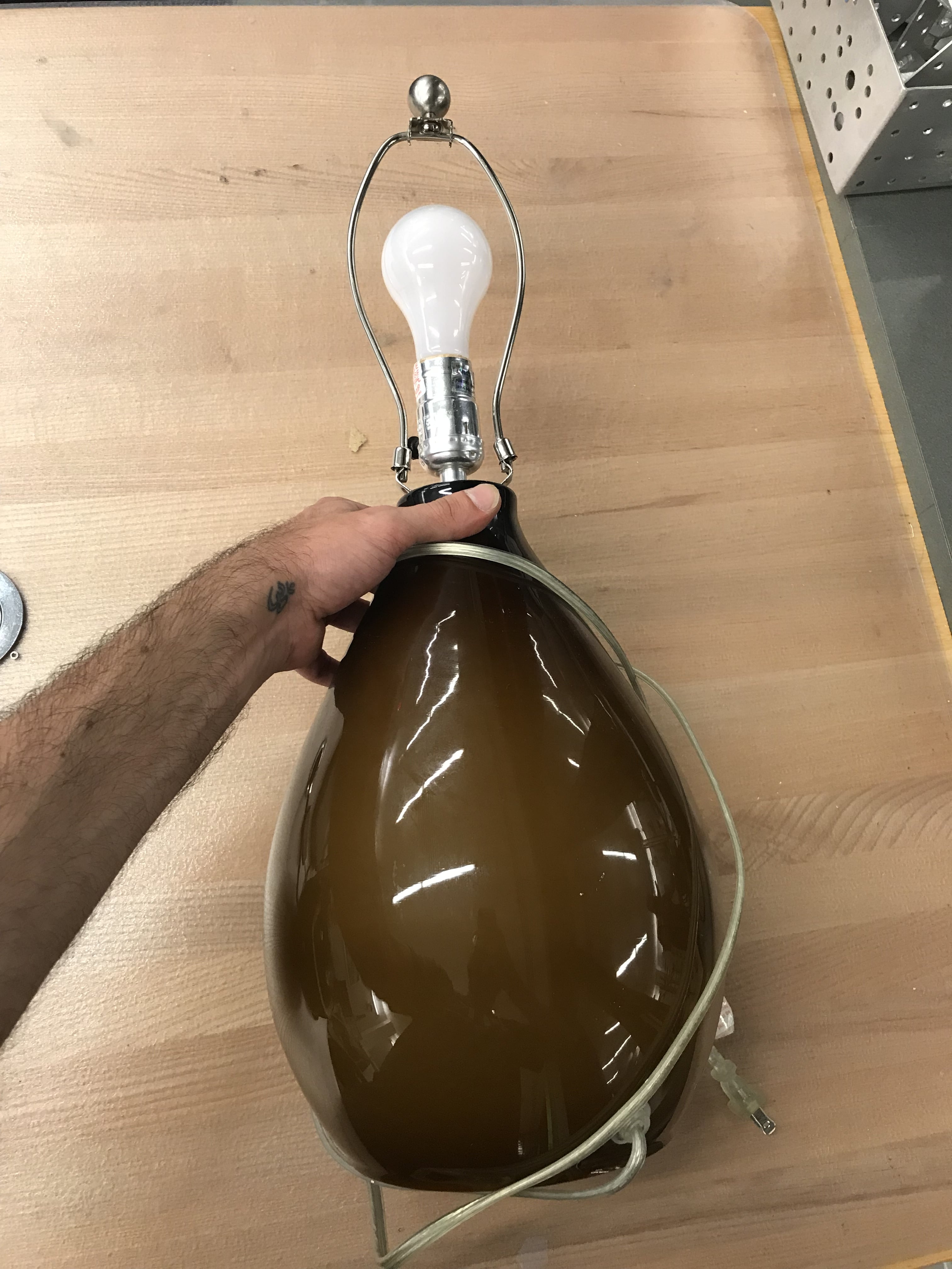
Nonetheless I finally managed to assemble the lamp shade for the lamp shown below.
My main learnings from this week’s assignment is to test the stability of the connection first before assembling a complex geometry like I did. Assembly turned out to be extremely challenging with a single connecting piece as all slices had to be inserted into the press-fit notches of the vertical connector at the same time for the cardboard not to bend away. This is a shortcoming of my current design and could have been resolved with a different style of connection and/or by using individual connector pieces for each adjacent pair of slices instead of a single vertical connector strip.