Work was completed during final project week unless indicated otherwise.
I wanted to create a final project that captured one of my interests and could be customized specifically for me. Nebulous idea contenders from the start of the semester included:
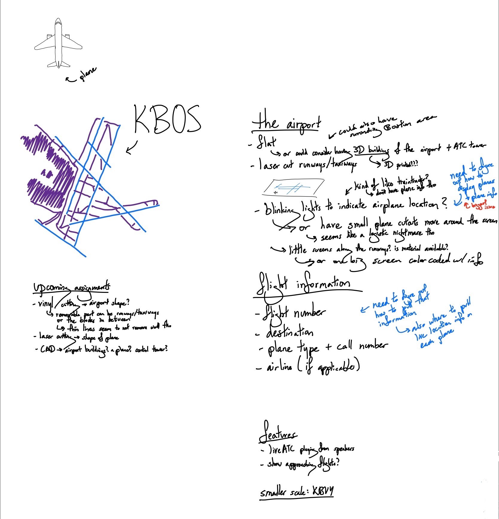
Ultimately, the idea that drew my interest the most was a to-scale model of Boston Logan Airport (KBOS) that shows the location of all the planes on the runways and taxiways at any given time. This was partially inspired by TrainTrackr, a live display of all the MBTA trains, made by some friends over at Cambridge Hackspace.
I played around with multiple different ideas of displaying plane. Using magnets to move 3D-printed planes around? Placing planes on sticks and use some sort of conveyor belt? Having sections of the runways function like seesaws and tipping marbles along the runway? Building a miniature version of the minature model of Knuffingen Airport in Hamburg, Germany? I eventually curbed my ambition and settled on using LEDs like TrainTrackr.
Some considerations that I kept in mind throughout the design process included: the final product being sized to fit on comfortably on my desk and having room to be added to if I wanted to expand on the project in the future.
In order to decide on the dimensions of my project, especially the number of LEDs I wanted, I needed to consider the data I would display.
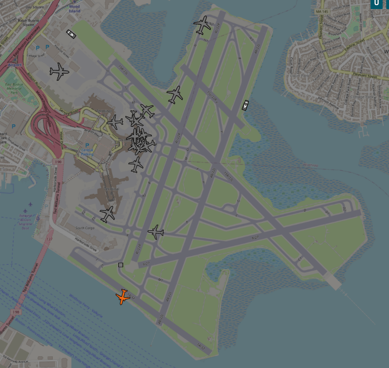
First was figuring out where to even obtain the live locations of airplanes on taxiways and runways. I knew that FlightAware shows flight paths and flight information of planes in the air but not for flights taxiing. I got my answer on October 19 when I crowdsourced from the MIT Flying Club Discord server. One option was the traffic layer on ForeFlight - a popular app among pilots, which is very much not free. adsbexchange.com has exactly what I want, though the API costs $10/month. airportviewer.com has the same info, but no API. Given these sources, I decided to place incorporating live data at the bottom of my priority list of features, and at least I could manually obtain real data (albeit past data) if I wanted to.
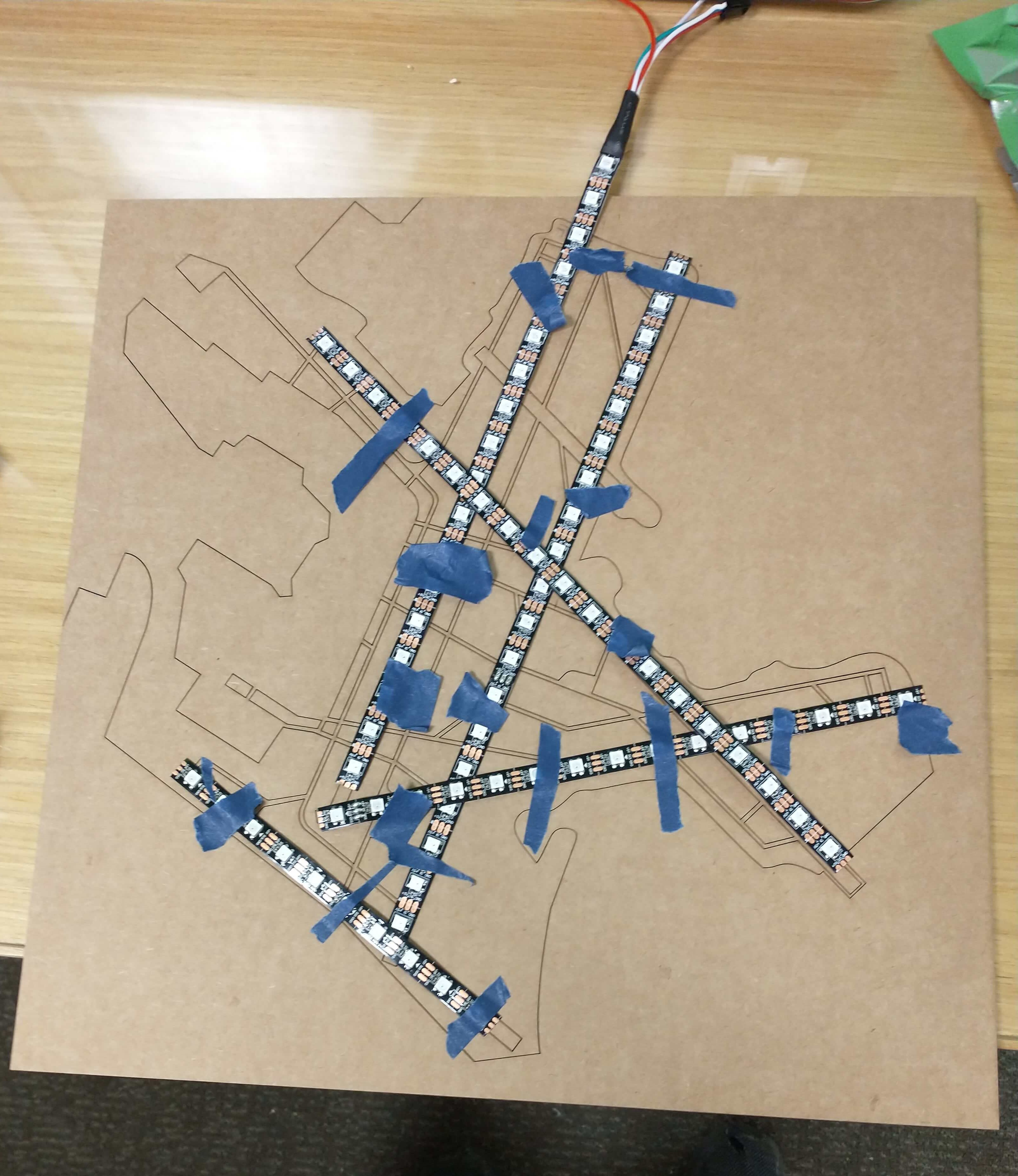
To get a sense of the potential dimensions of a desktop-sized KBOS model, on October 31, I printed out a map of the airport on four sheets of paper, which I measured a week later on November 8th (about 16 in by 17 in), which would fit in the 18 in by 32 in laser cutter in EDS. Dimensions of my project would affect what materials I'd be able to use. Acrylic comes in large enough sheets to fit these dimensions onto one piece of acrylic; available pieces of wood, however, are 11.8 in by 24 in, so I would need two pieces.

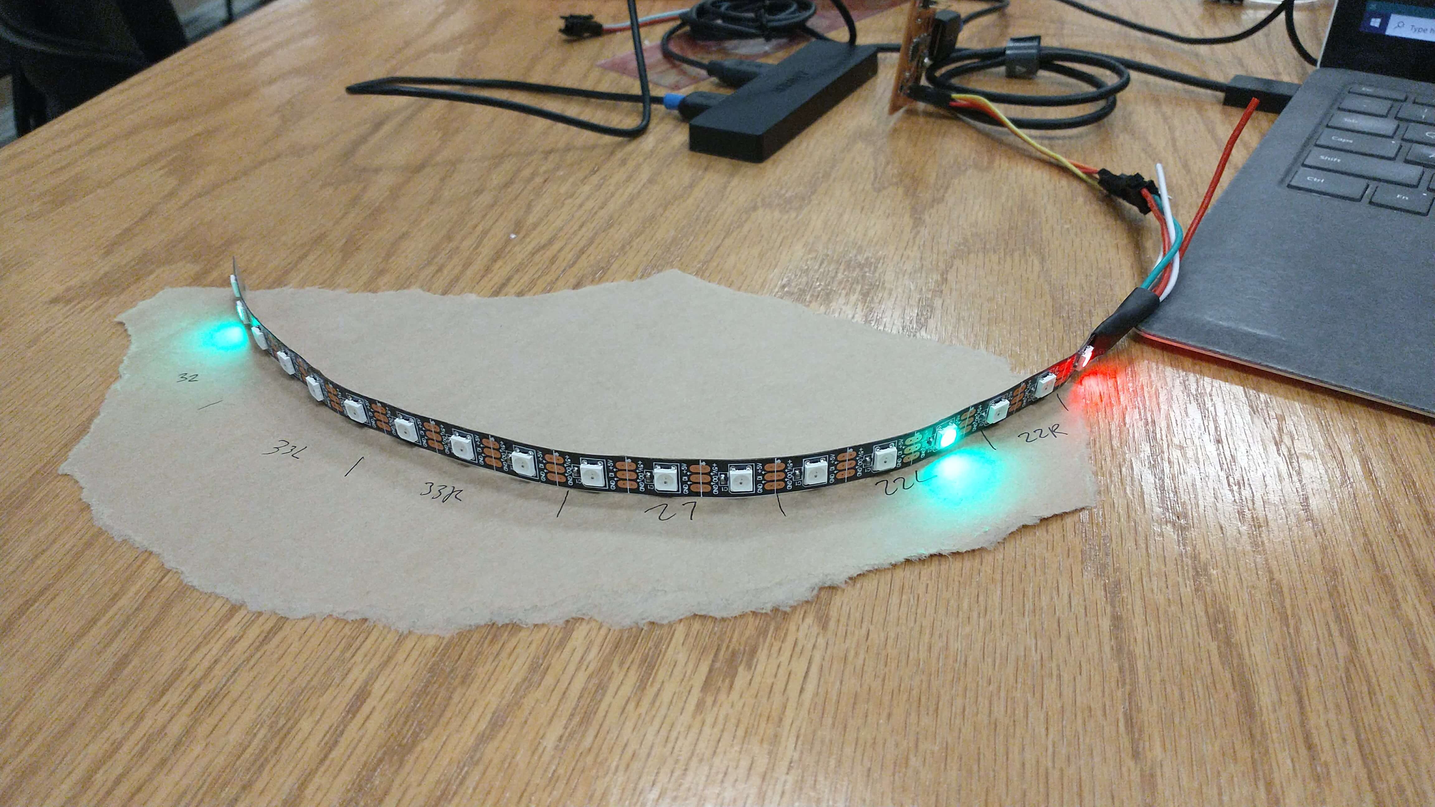
At the end of November, since I needed LEDs to arrive on time for me to start working, I spent a while watching ADSB to decide how far apart to space the lights to display ADSB's data. I tracked the number of increments that planes needed to travel a section of taxiway or take off from a runway. From this, I came up with an ideal number of either 3 or 6 LEDs per centimeter of my paper map. I also estimated the total length of runways and taxiways by measuring my printouts of the KBOS map. When my calculated total of LEDs reached 400+ LEDs, and I found out that KBOS has 15 miles worth of taxiways, I decided to focus the scope of my project on lighting up runways only.
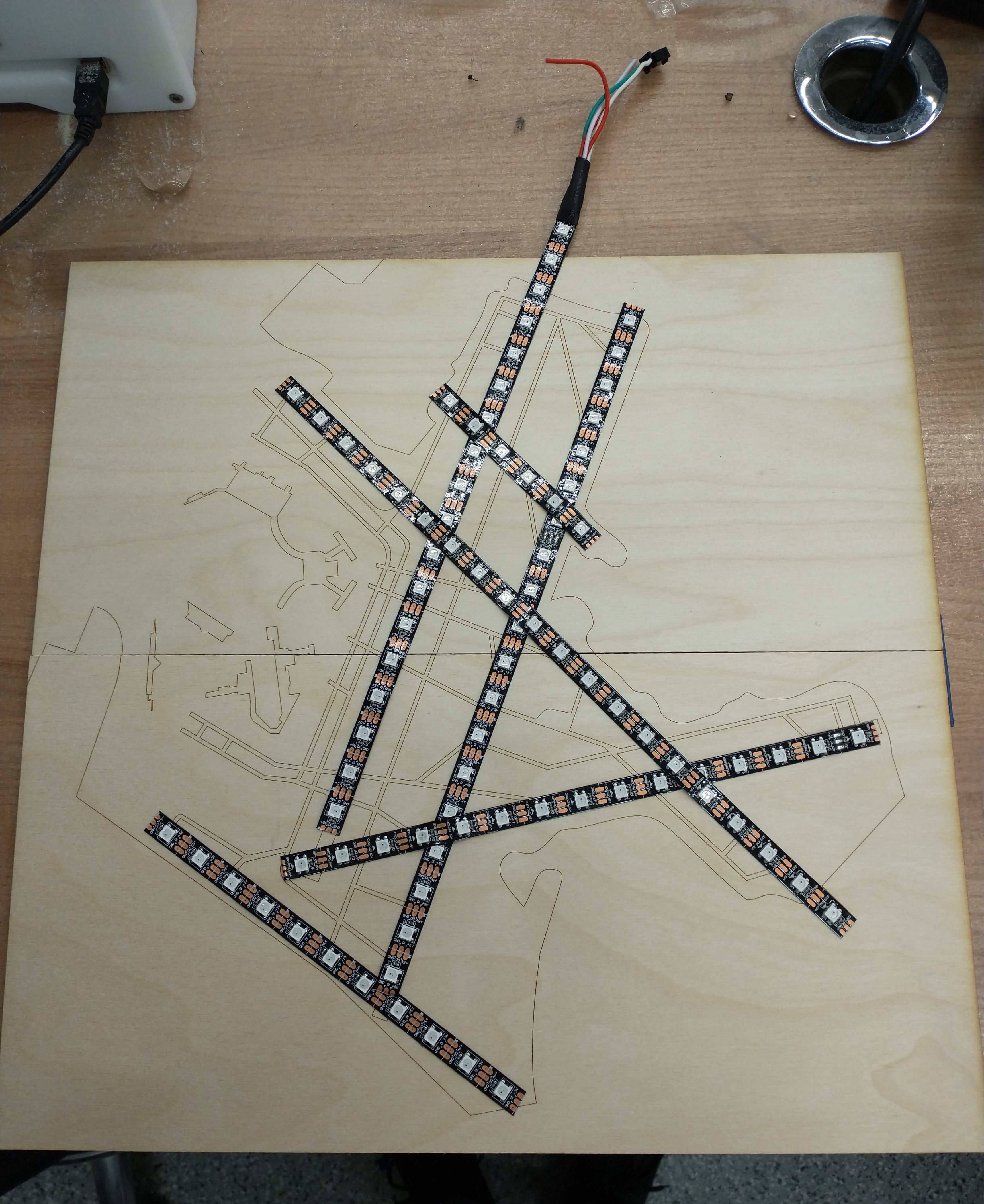
Anthony recommended that I use LED strips, which is discussed in greater depth in another section below. The strips would thus constrain how far apart I space the lights and how long a runway would be. If I wanted N LEDs to span the length of Runway X, the spacing between these LEDs would determine how long Runway X would be on my model and thus the dimensions of all the remaining runways. The large 4-sheet paper map proved useful again to be measured against LED strips and get a sense of how many LEDs would fit on the different runways.
I would want a runway width that is thicker than the width of the LED lights, and its size relative to the overall LED strip width isn't an issue. I'd also have to consider the intersections between runways and ensure that LEDs for 2 different runways won't overlap each other. Taxiways would probably end up too thin for LED strips, so if I eventually wanted to add LEDs to those, I could use individual addressable LEDs (instead of strips) or compromise on appearances or how brightly the taxiways can shine.
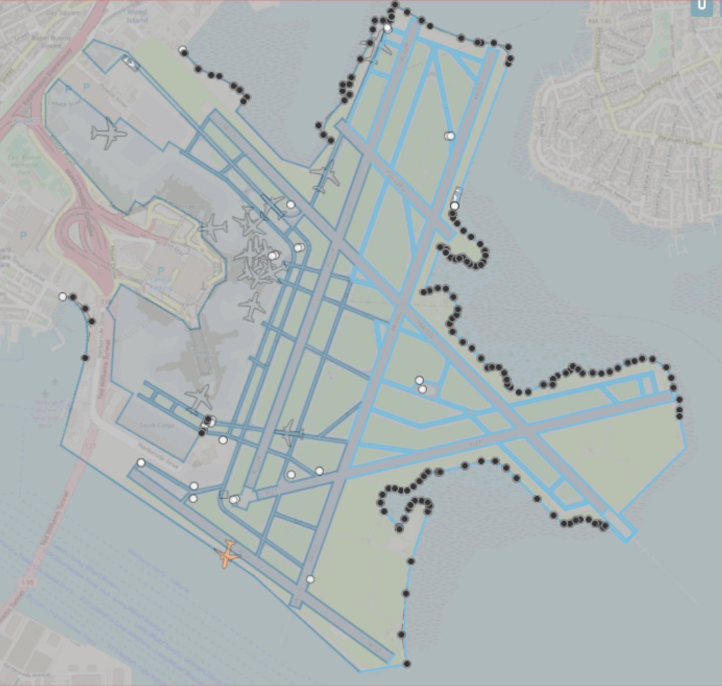
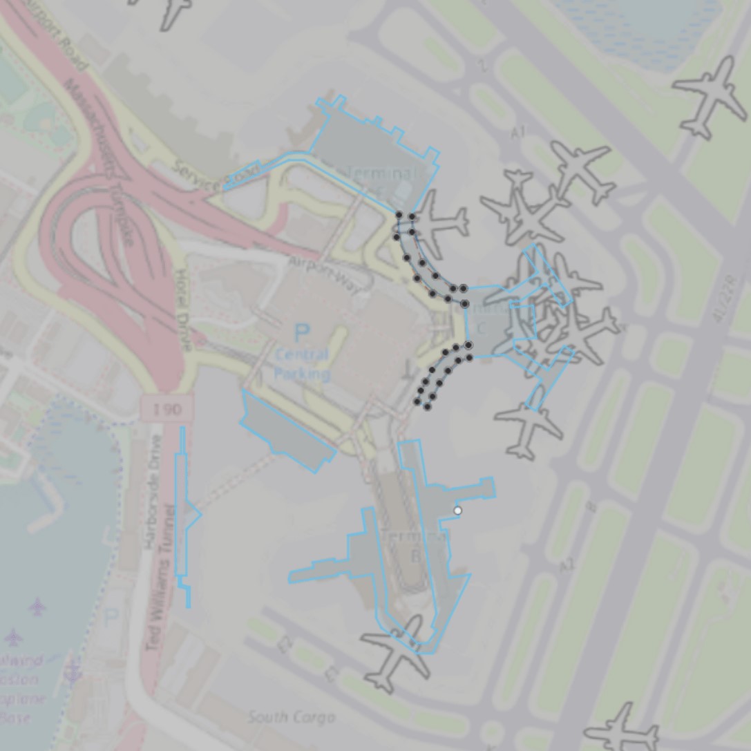
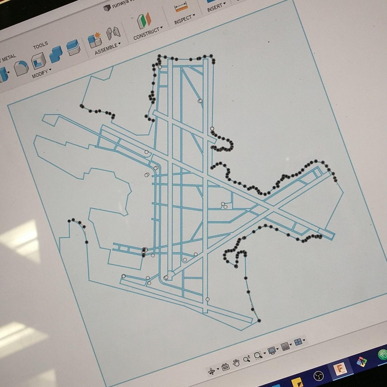
Though someone recommended that I take a photo of the airport and laser cut that directly, I opted to CAD my runways and just manually trace them out in Fusion. All the potential photos I saw were rather pixelated; they each had text I'd have to get rid of anyway; and I'm not versed in photo editing. I screenshotted from ASDBExchange (where I'd ideally pull airplane location data from) and referenced the FAA KBOS Airport Diagram. Using lines and Control Point Spline, I sketched out the outlines of the runways, taxiways, and the "island" that KBOS is on.

I added a box around the airport so that the entire model could be cut out. Fusion crashed while I was working on the island outline, so I unfortunately had to redo it, as well as when I was trying to add road outlines and adjust the edges of the runways.
Now that I had my airport outline to be scaled up or down, it was time for me to finally decide on the dimensions of my project. I first tried scaling Runway 14 in my CAD to its corresponding size in my paper model, which was too wide. I then decided to go from my initial plan of 18 LED lights for Runway 22R to 16 LEDs, which resulted in a runway length of 10.5 inches. I scaled up my CAD sketch's 9.469-inch-long Runway 22R to 10.5 inches. (I'd also have to use this same scale factor to scale up my airport buildings if I used the same canvas to sketch them out.) This scaling resulted in the entire airport model being 13.559 inches by 14 inches, which I enlarged to ~15 inches by ~15 inches to have more whitespace between the edges of the island and the edges of the model.


Although I was thinking of labeling the runways and taxiways, I realized there was no point, as the runways would be covered by LEDs, and the taxiways are too thin for any text to be comfortably visible.
Since my airport outline lies all on one plane (geometrically, not on an aircraft) and doesn't consist of parts the way my laser-cut plane construction kit does, I was at a loss at first on how to turn my sketch into a dxf file. I tried to directly export the file from Fusion as a dxf, which resulted in two main issues. First, when I opened up the file in Corel, it was missing any curves that I had made using Control Point Spline - particularly for the island outline. Second, Corel couldn't load the file with the right dimensions; no matter which units option I chose, the scale was either completely the wrong order of magnitude or were slightly differnet dimensions. I looked into exporting a sketch from Fusion into a PDF, but cursory Googling did not indicate this was possible.
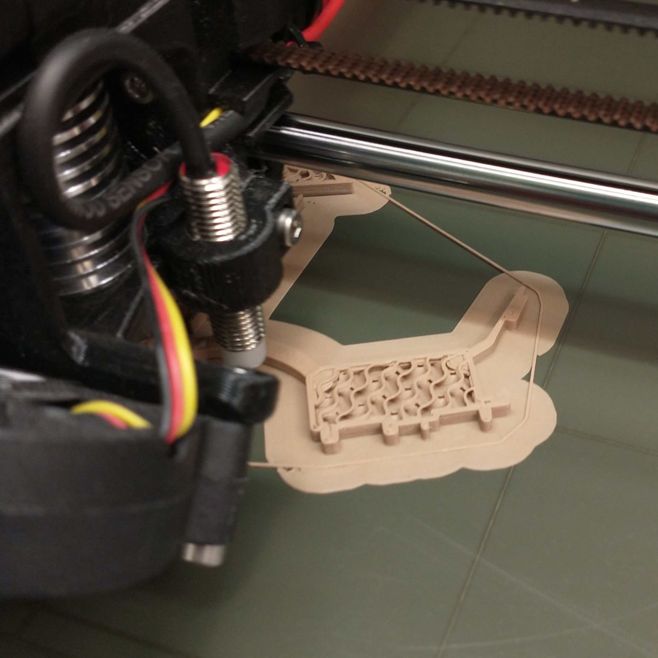
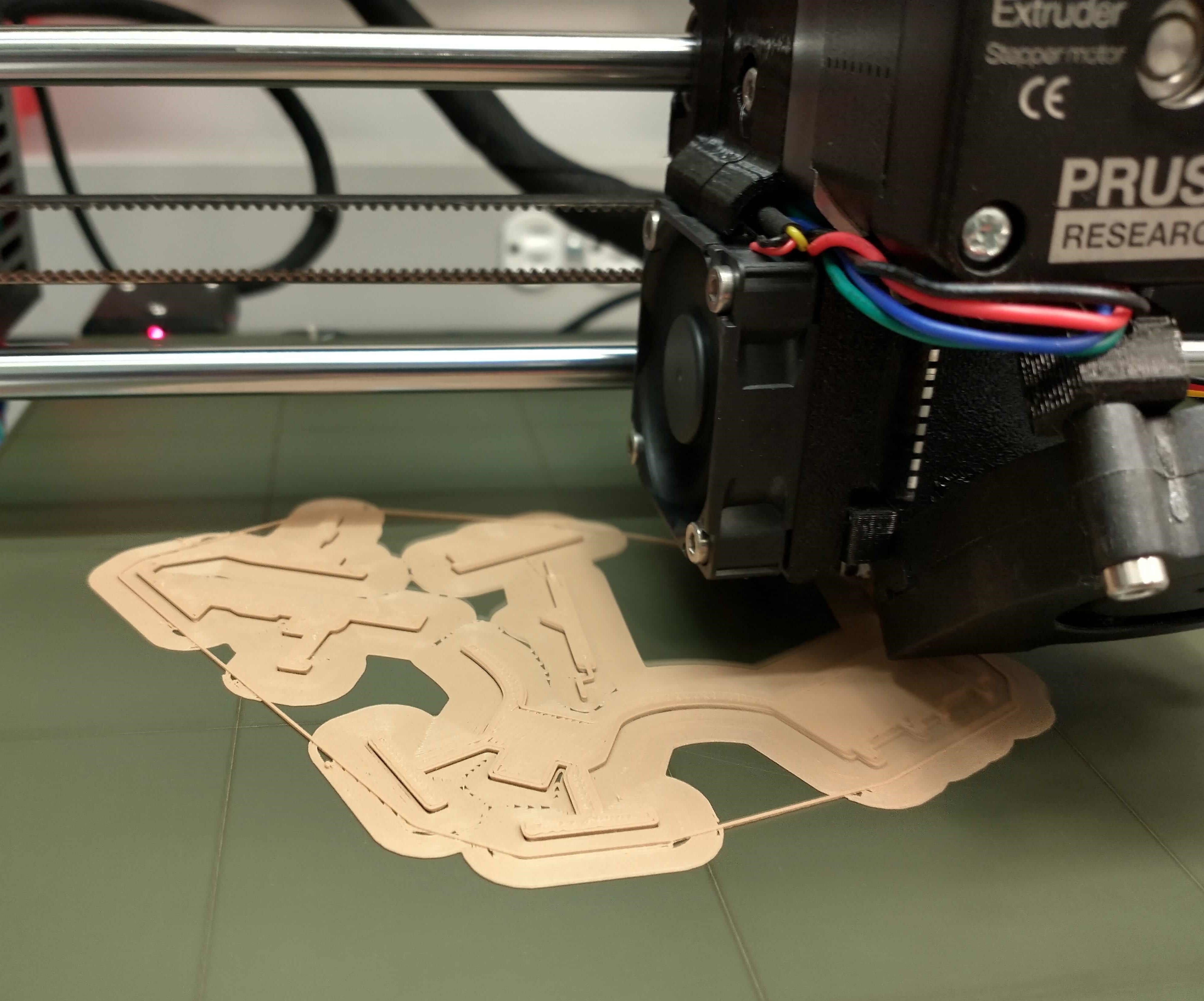
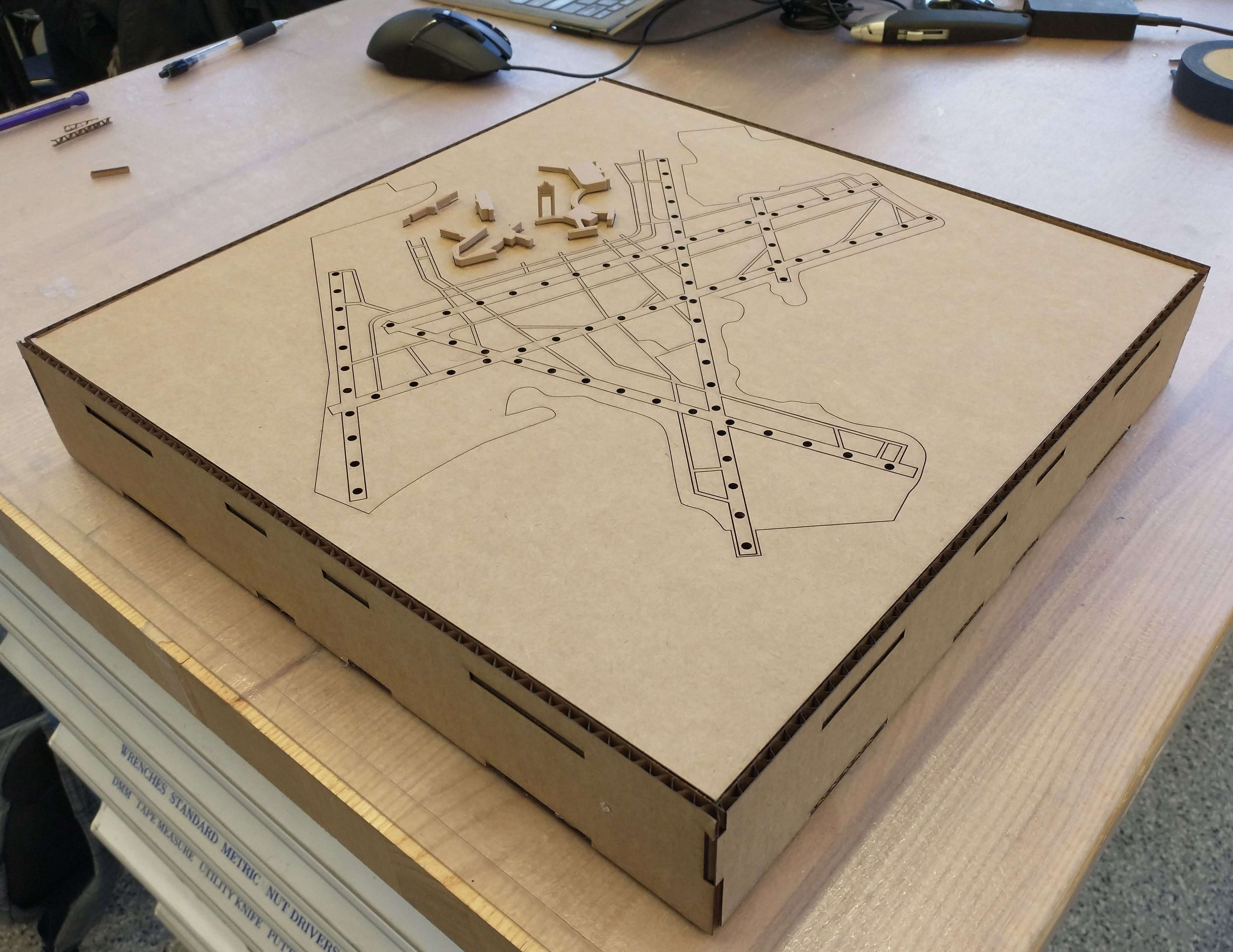
As revealed in one of the above photos, I thought to extrude different parts of the sketch (to include all the outlines I wanted) and align the dxfs manually in Corel. By creating bodies with the desired outlines, setting kerf to 0.15 mm, I was able to use the Fusion plug-in that Ben found back in Week 2 to generate dxf files. This plug-in also solved the dimension issue I had earlier. Additionally, in Corel, after aligning the dxf files, I had to ungroup all the lines to be able to set colors for different lines.
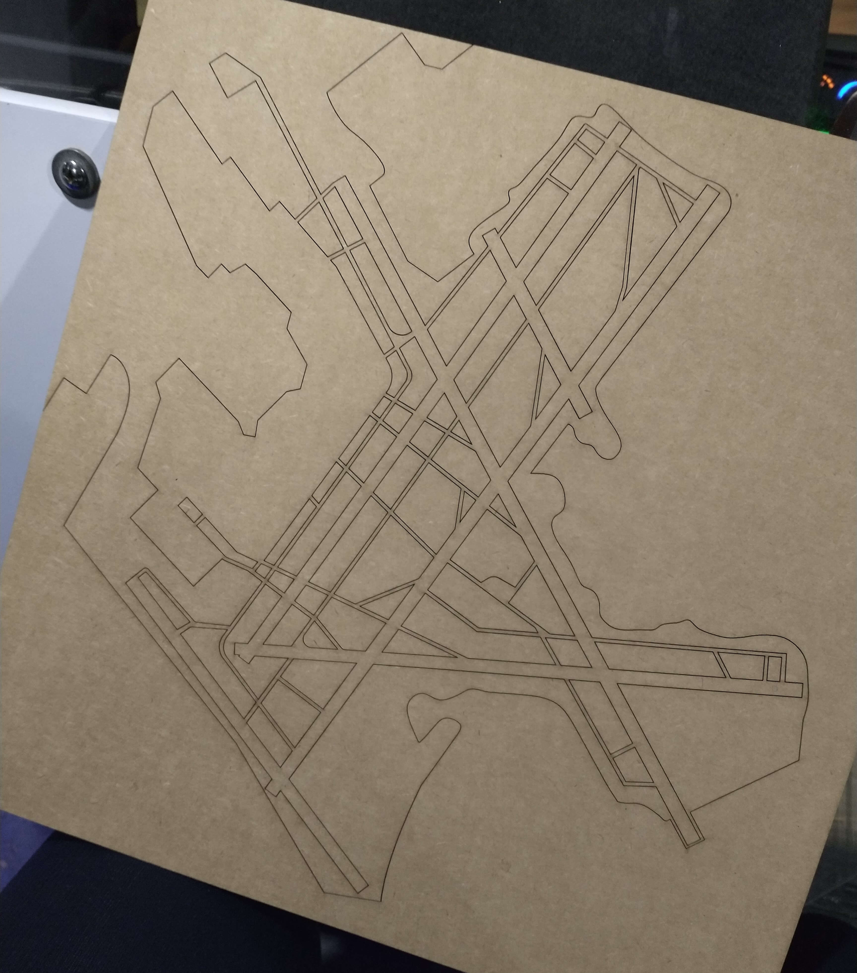
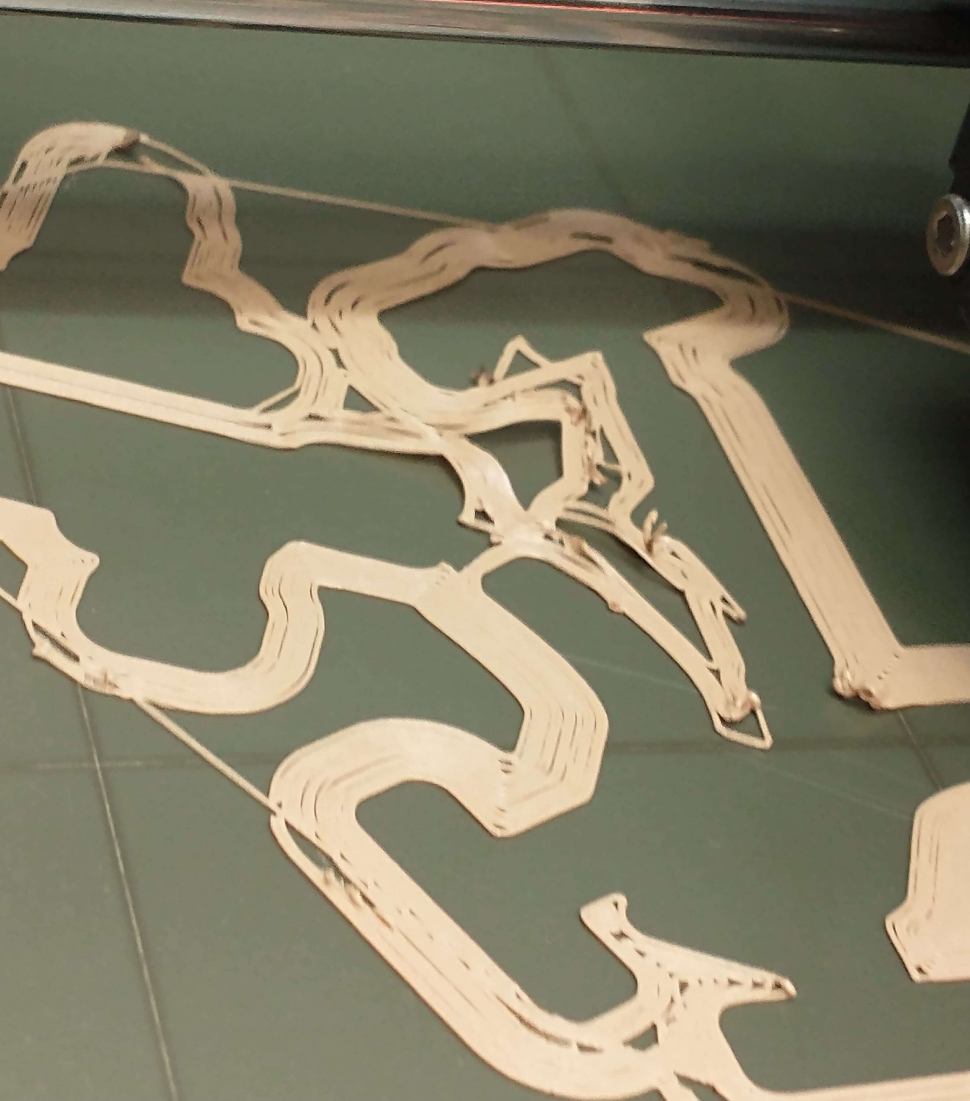
As usual to test out my design, I used cardboard, which I had tape down, since it was very much not flat, which messed up the laser cutter's focus. I checked to see if rastering resulted in anything showing up on the cardboard (and indeed nothing did), so I used Engrave instead, which is much faster, and the test piece turned out gorgeous. Laser cutter settings for power, speed, and PPI were the same as determined in Week 2.
In addition to having the outlines of the runways and taxiways, I also wanted to-scale models of KBOS's buildings and started with the 5 terminals. I chose to 3D print the buildings for the quickest, simplest, and most detailed option.
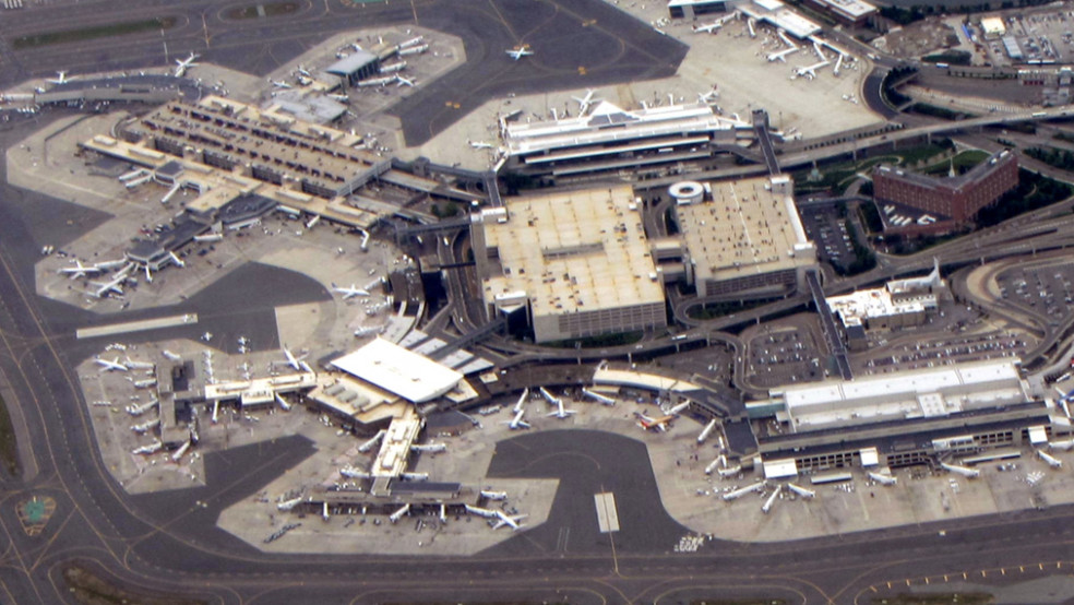
Using the same ADSB screenshot canvas for general building shape and location, I sketched out the outlines of the 5 terminal buildings, using a another, more detailed terminal map for reference. Based on this photo, I estimated the heights of the terminal buildings.
I compared Terminal E to its length and designated its height in my model to be 5 mm. I set the heights of Terminals A Satellite, B, and C to be 75% of Terminal E's, Terminal A to be 125%, and the Terminal C-to-E Connectors to be 50%. Terminal D does not exist. Picking out these measurements was a reminder of how small these buildings are compared to 2-mile-long runways, so I worried that some of the details I illustrated in my CAD wouldn't come through in the 3D print.

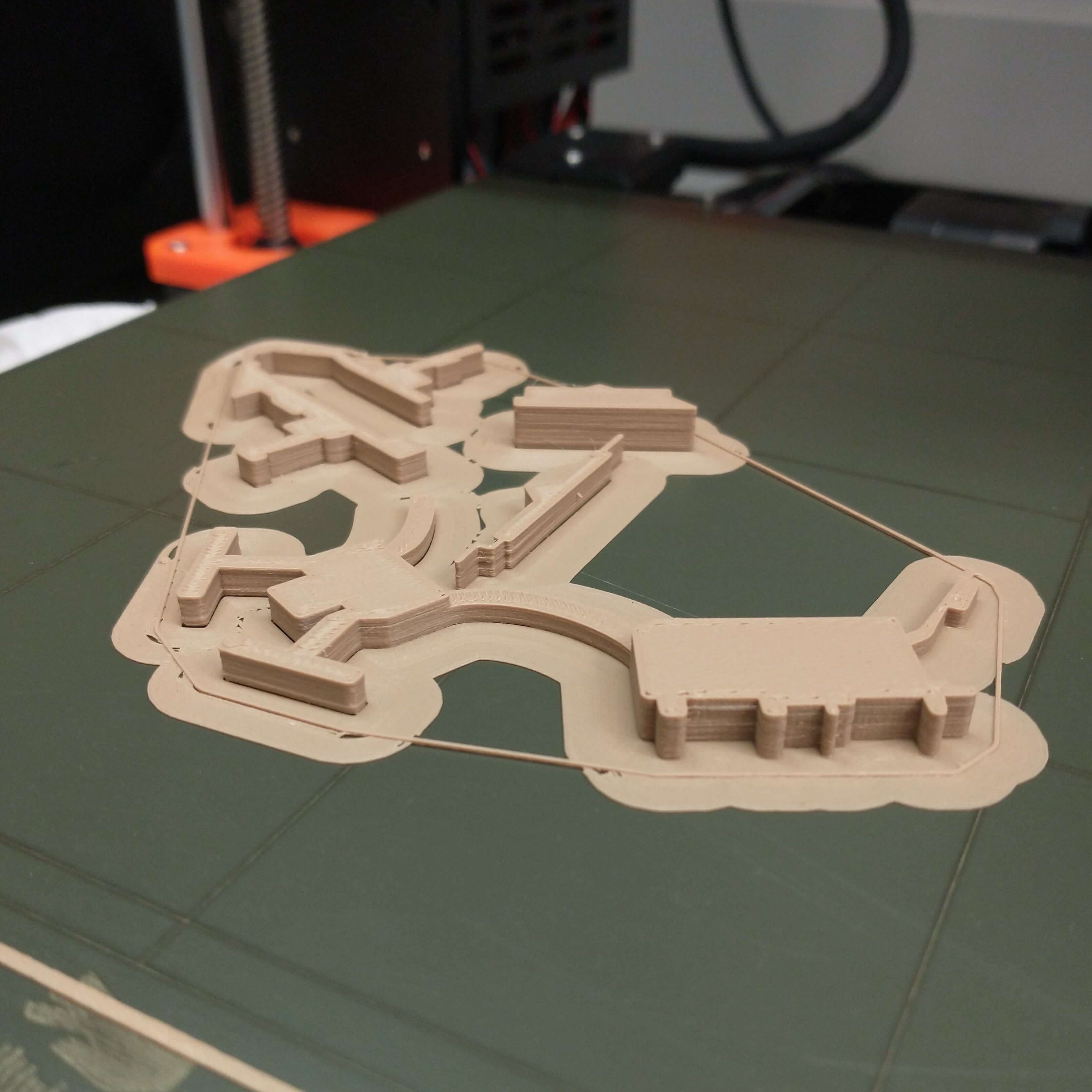
I wanted to use the sawdust PLA filament that I used for my KBOS tower in Week 4 - otherwise white PLA. Luckily the sawdust filament was already loaded in the Prusa. I exported my CAD as an STL, opened it up in PrusaSlicer, set infill to 20%, and added a brim - which came to an estimated print time of 1 hour 1 min, even though the parts are just 5 mm in height. Anthony and I moved Terminal A Satellite into the center of the c1uster, which saved a grand total of 2 minutes of print time.
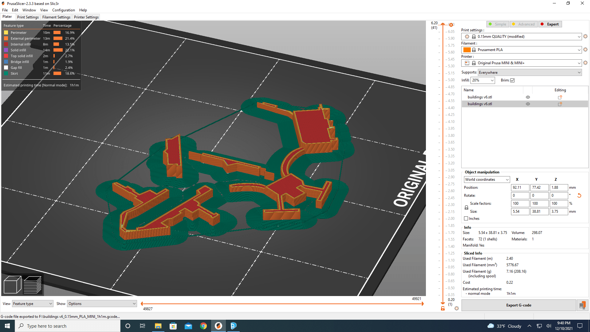
During the first print attempt, the brim layer came loose from the machine bed, so I stopped the print, wiped down the bed with some isopropyl alcohol, and restarted the job. For this second attempt, I slowed the machine speed down from 100% to 67% (by turning the dial) for the first few layers, which bumped the estimated machine time to 1 hr 31 min, if we'd used that speed for the entire job. After about 25 minutes and the lower layers completed, I turned the machine speed back to 100%, which gave me 43 minutes remaining.
When I realized how small my buildings were, I could've double checked with the 3D printer design characterization rules we established in Week 4. Since the print time was just an hour, I figured I'd just go ahead and print the buildings and see what would happen. And Anthony and I were both rather impressed by the Prusa and how it managed to capture all the details I'd put into my CAD.

After positioning the terminals on the airport outline, I decided to include the building footprints on the laser cut of the airport, instead of the road outlines.
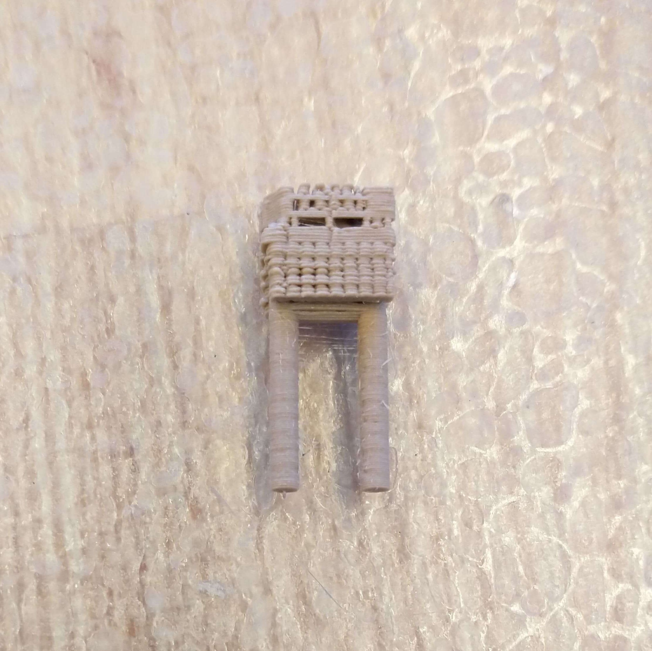
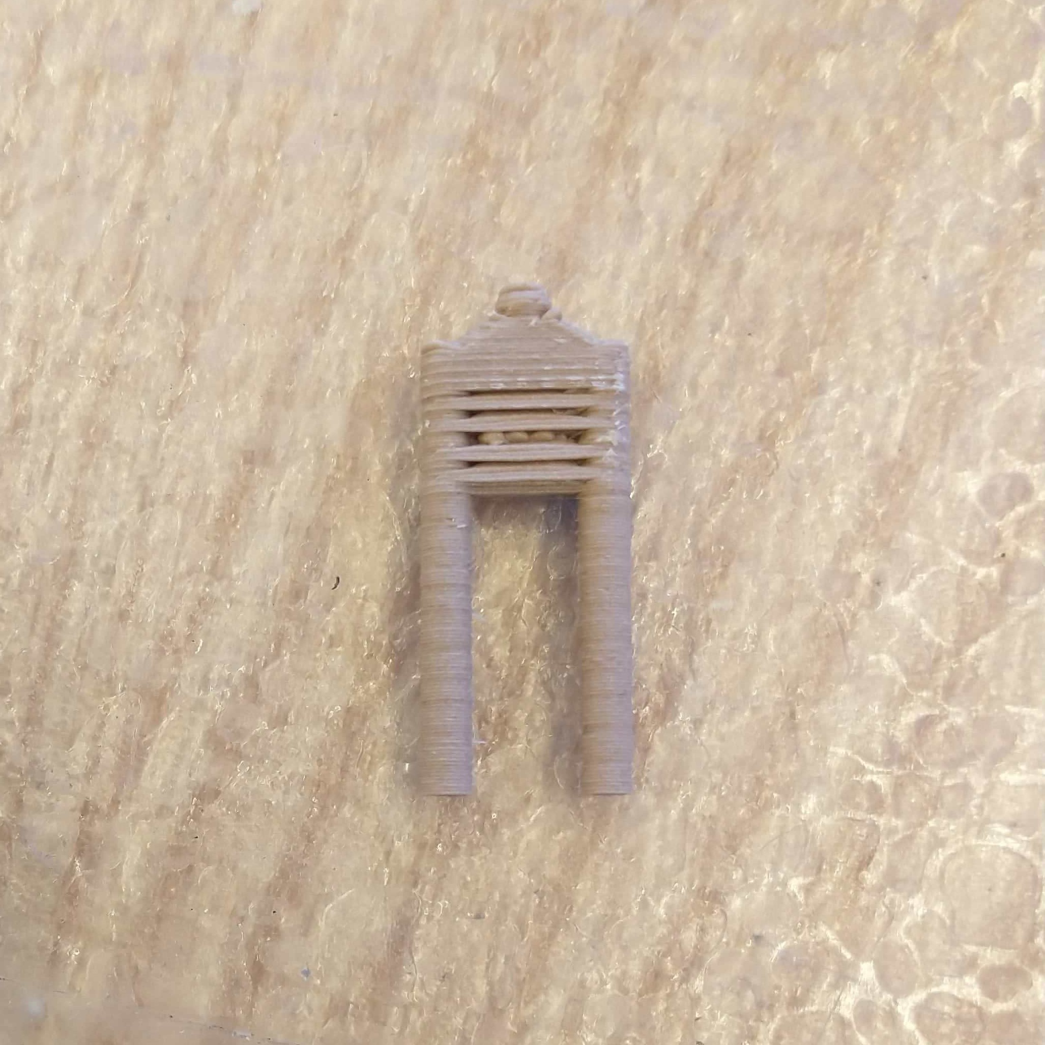
Now that I had my 3D-printed terminals, I moved onto adding the air traffic control tower. I took my CAD from Week 4, scaled it down to match the proportions of the terminals (from the original CAD of 20.181 mm width to that of 8.658 mm), and printed it on the Prusa in the same orientation and with the same supports as Week 4. I used honeycomb support material for added density and to better adhere to the bed. Finding the location of the KBOS ATC tower took a surprising bit of time. Turns out it's behind Terminal C, as shown in this photo.
A conversation with Anthony on October 21st gave me a few options. I could use charlieplexing to use n pins to control n(n-1) LEDs, which would let me turn on pins one at a time. However, I wouldn't be able to turn on multiple pins at once, unless for very specific configurations. Thus, charlieplexing would work if I only wanted to control one runway but not if I wanted to control multiple at once with the same board.
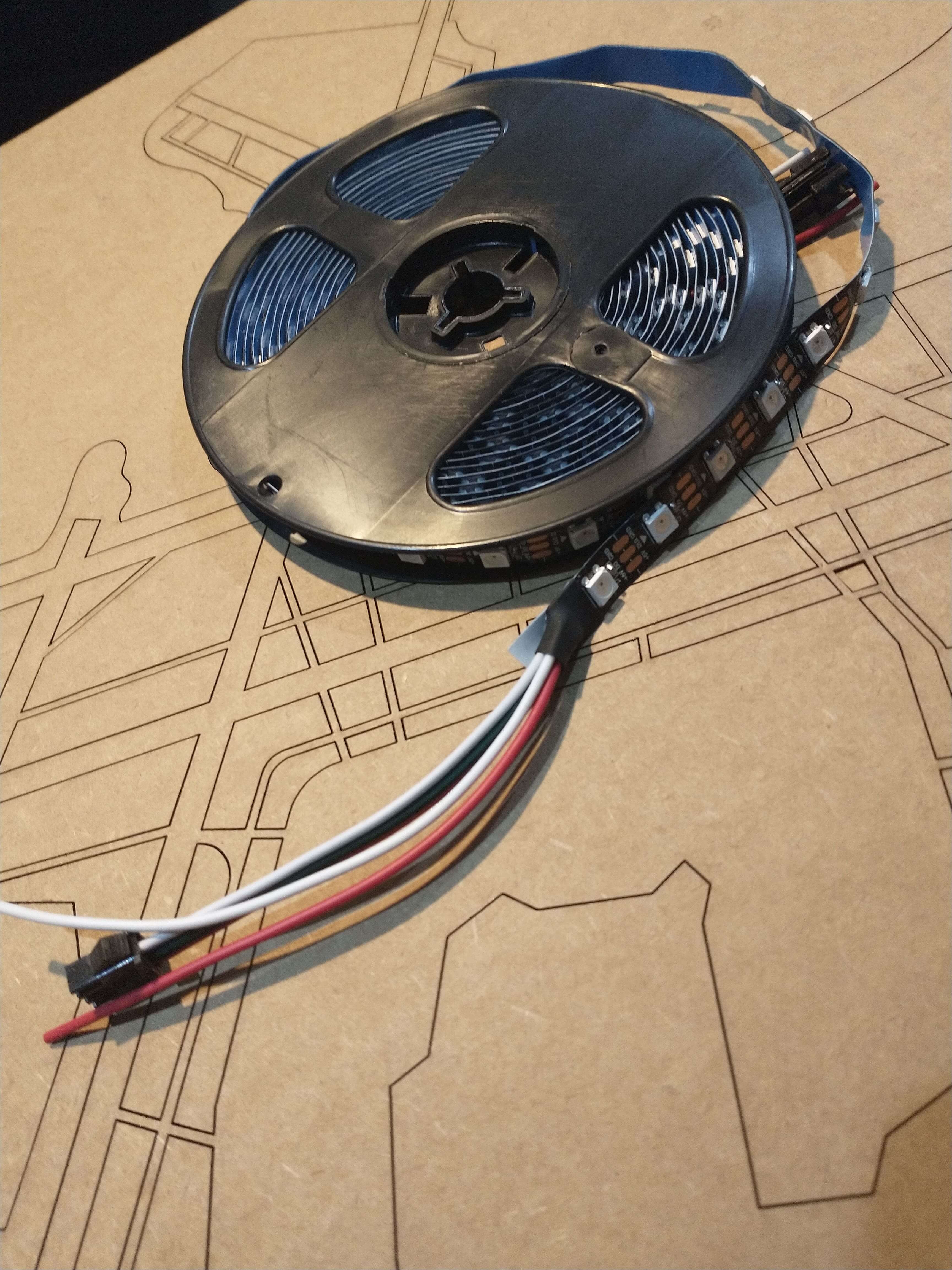
Another option was addressable LEDs - LEDs that are set up in series and aware of their order to each other. These LEDs can thus be controlled by one pin. Addressable LEDs come in RBG verisons, LED strips, and individual LEDs. Individual ones can be laid out in any shape you want, and strips can save a bit of time and effort. ALITOVE WS2812B LEDs, for example, is $34 for a strip of 300 LEDs.
I also consulted Cambridge Hackspace on November 9th about the LEDs they used for TrainTrackr; they used LED drivers and 0805 LEDs that aren't addressable.
I chose to go with the addressable LEDs. Anthony ordered both individual ones and strips. Given time considerations, I decided to use LED strips for the runways and potentially individual LEDs in the future for the taxiways.
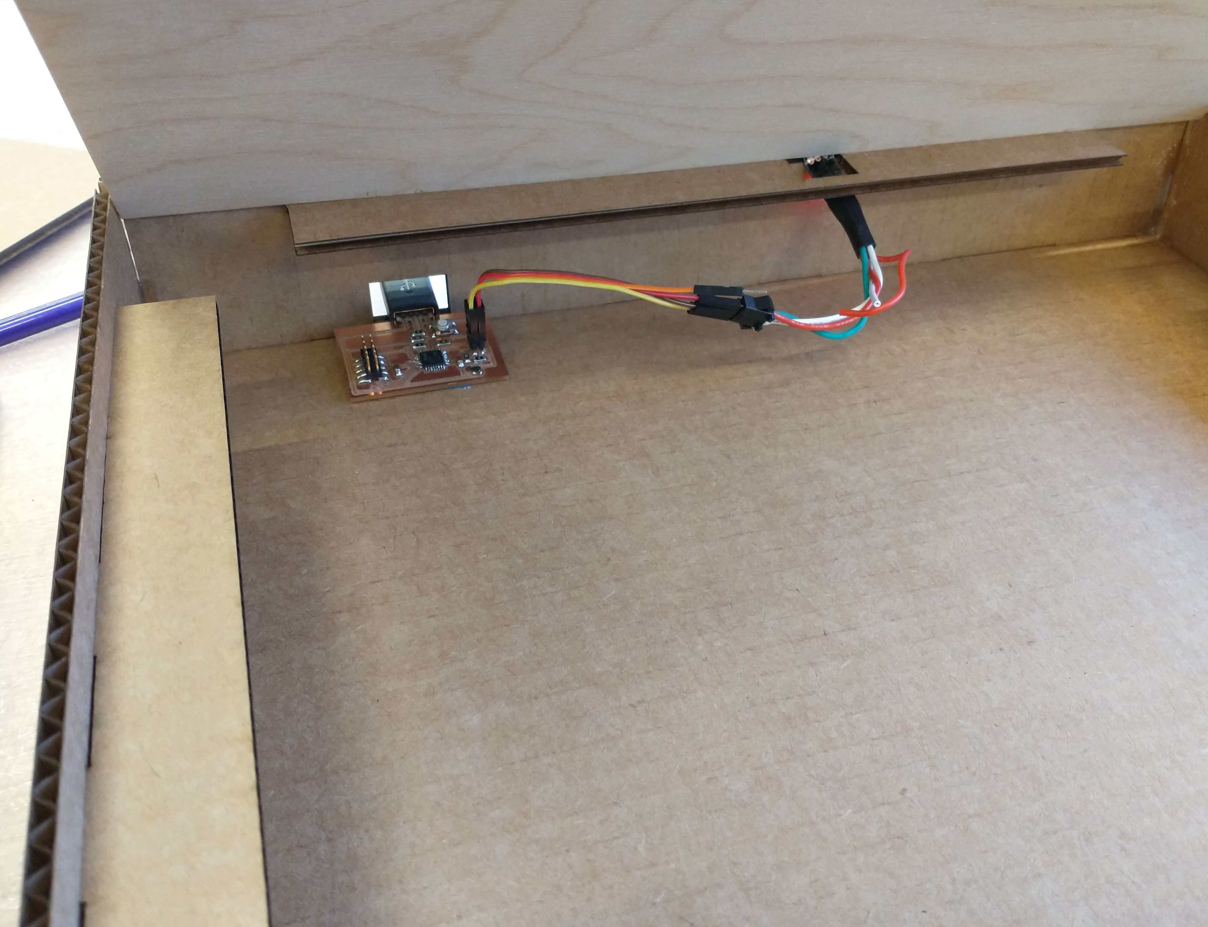
From previous weeks, I had a number of PCBs I could potentially use for to control my LEDs - most notably, I hoped to use my plane PCB with a SAMD11C from Week 9. The LEDs just need to be controlled from a digital pin; unlike the OLED display, it doesn't matter which kind of pin hardware-wise you attach the LEDs to, as settings are primarily controlled through software. So the LEDs can be attached to TX, RX, SCL, or SDA. The second end of the LED strip doesn't need to be plugged in anywhere and serve to connect mutiple LED strips if desired.
For the particular roll of LEDs I am using, the red wire corresponds to power, green to data, and white to ground. Anthony helped me verify this by using a voltmeter and putting it on continuous. The voltmeter should beep if you are touching the voltmeter GND to GND, etc. The 1x6 connector on my plane's PCB, from left to right, is VCC, GND, TX (connected to PA04), and RX (connected to PA05). (Sidenote: I should put together a short "About the PCB" summary for each of my boards, that covers the pin order, characteristics, etc. For example, the microcontroller on my plane PCB is upside-down. When I go back to use PCBs I've already made, I can just refer to one chart and not have to dig through my entire documentation for information.)
I first tried using FastLED,which unfortunately doesn't support SAMD11C, so I'm following this lovely tutorial on using Neopixels. Neopixels has a number of example Arduino sketches, that were very useful, as well as some best practice recommendations that Anthony said I could ignore for my purpose.
I started off simple - getting the first LED in the strip to blink. Despite hours of debugging, the LED resolutely did not light up. I was even concerned that I'd somehow manage to damage my plane PCB during transport. I tried using my Week 11 PCB (with a SAMD21E), which didn't work either. Anthony had the brilliant idea of using his computer to upload some Neopixel code to the SAMD21E (using SDA with Pin 16).
Changes we made include: setting the board to SAMD21E18A instead of the default SAMD21E15A. Anthony also had me set my Neopixel library to the version matching the one on his laptop - version 1.7.0. Neither of these changes got the LEDs to work with the SAMD11C, however, so I'd just use the SAMD21E for my final project.
To standardize the wires connecting the SAMD21E to the LED strip:
Wire Colors: Pins on the SAMD11E PCB
Orange: SCL (top left)
Brown: SDA (top right)
Yellow: GND (bottom left)
Red: VDD (bottom right)
Wire Colors: LED Strip Wires
Red: Red
Yellow: White
Brown: Green (for Pin 16)
If the LED strip's wires are ordered red, green, and white (from left to right), then corresponding wire colors should be red, brown, and yellow.
In lieu of using realistic data to light up the LEDs, for demonstration purposes, I made up my own data. I also wrote code under the assumption that only one LED per runway is lit up at any given time - which is consistent with reality, as there should never be 2 planes on the same runway at any given time. The LEDs are also zero-indexed.
I started by defining my runway names in my code - referring to them by their names going clockwise starting from north. (While Runway 22R and Runway 4L both refer to the same physical runway, I refer to that runway as 22R in my code, instead of 4L. Similarly, I use Runway 27 instead of Runway 9.)
I first wanted to get one runway to work, getting the right lights to turn on and off to simulate a plane moving along a runway. This hello_world function determined which LED to turn on (and which to turn off) solely based on how much time had elapsed.
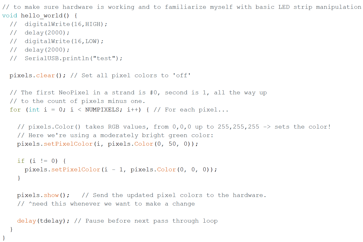
Sidenote: the NEO_KHZ800 in "Adafruit_NeoPixel pixels(NUMPIXELS, PIN, NEO_GRB + NEO_KHZ800);" specifies speed of communication and has a 400 option.
I also experimented with different colors and brightnesses. I'll set these as variables at the start of the code.
Hardware-wise, having multiple runways is simple. I just need to use wires to connect different segments of LED strips and thus use the same pin and microcontroller to control all the runways the way I would for one.
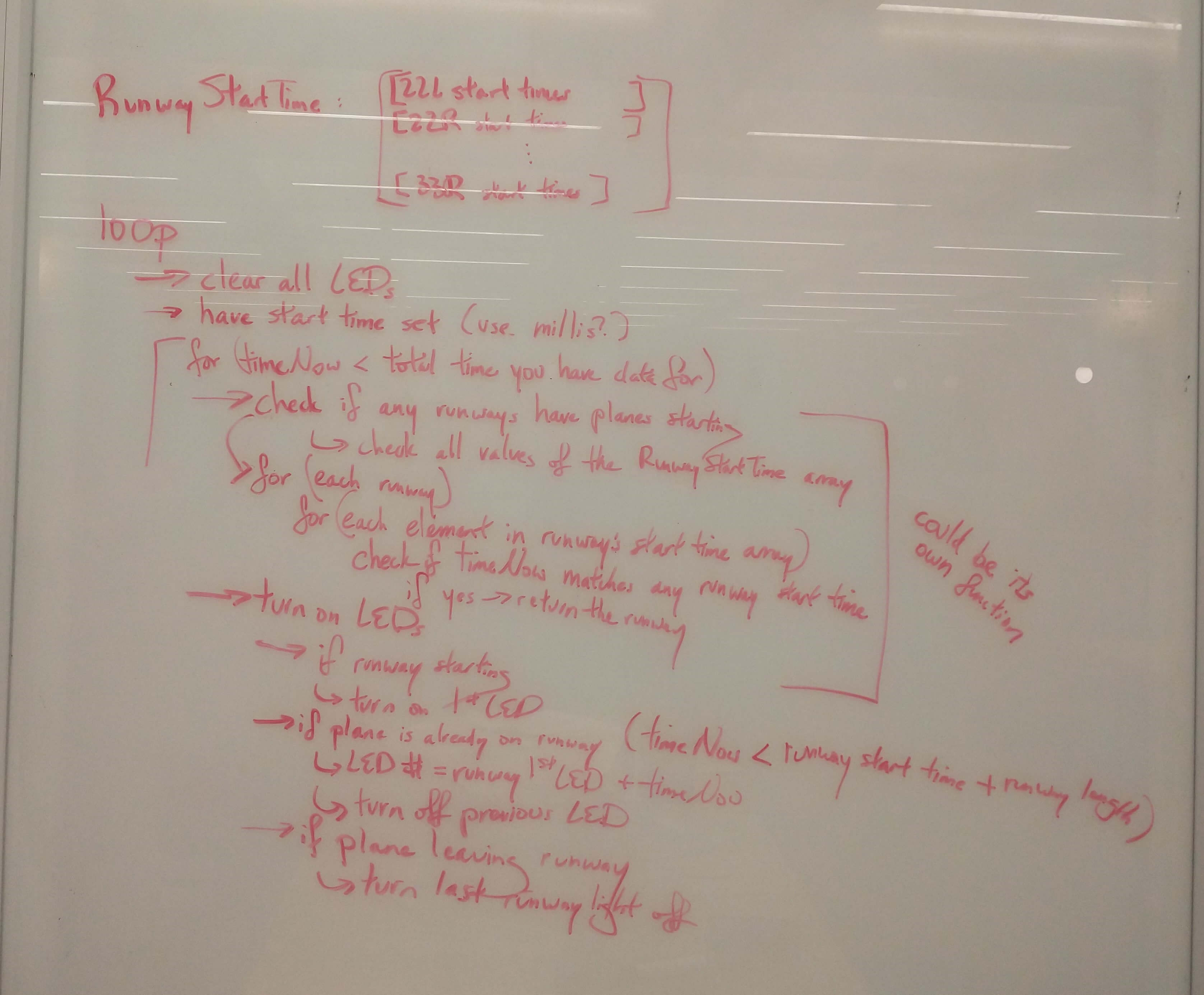
Coding multiple runways was going to be much trickier. I would only be able to light up one runway at a time if I used an elapsed-time approach that I did for my hello_world function. I could specify which LEDs should be on by having a massive 2D array indicated plane positions, with rows corresponding to timestamps and columns corresponding to each LED, and with elements of 1 if a plane is present and 0 otherwise. The approach I went with was by representing each flight with a runway and a timestamp at which it begins traveling on that runway. I assumed (for this version of my final project) that the planes would travel at the same constant speed along the runway. Runway lengths are known, so this method of indicating flights is superior to the position array approach.
I also had to figure out to best store this information. One idea was to have 6 arrays, each corresponding to an individual runway, whose elements represent what time a plane begins to take off or land. I could then make a larger array that stored these 6 arrays. Another approach is to have one array that sorts all the flights by runway start time, where each row is an array with two elements: the start time and the runway number. I went with the first idea, put together some pseudocode - my first time pseudocoding in years, to be honest - and started coding.
To test my code, I used a short segment of 18 LEDs (which would become my Runway 22R) and set the runway lengths to each be 2-3 LEDs long.
One of my main challenges was figuring out how to indicate which lights should be on. I decided on having a 1x6 array, called lit[], with one element corresponding to one runway. If a runway had no planes (and thus no lights on), the value of that runway's element would be -1. If a runway had a plane, this element would be the index number of the LED indicating where the plane was. I had a similar array, called most_recent_startTime[], that stored the takeoff/landing time of the most recent flight on that runway.
If the board disappers from the Tools list, try forcing it into bootloader (by double pressing reset button - I'm so glad I added a reset button when I made this PCB). Check the clock source setting as well and make sure it's not set to crystal. At some point, I tried outputting text to the Serial terminal, which somehow caused the port to disconnect and gave me notifications that the USB wasn't found. This happened around the same time that, unknownst to me, the laser cutter started on a job, so I smelled something burning and thought that I managed to set my board on fire. I reset my board with the button, reburnt the bootloader, did some test uploading to see if the board still worked, then determined that it was Serial that was the issue. It turns out that I simply did not define arrays sufficiently enough to print anything to the terminal.
Some More Bugs I Ran Into:
Some Notes About Coding in Arduino
I finally got all the runways lighting up at the proper times (and made a copy of that code called "multi-runway"). I ran my code using test cases, such as if runways with higher indexes have planes taking off first, if two runways have flights with the same start time, or if a runway's start time array wasn't sorted.
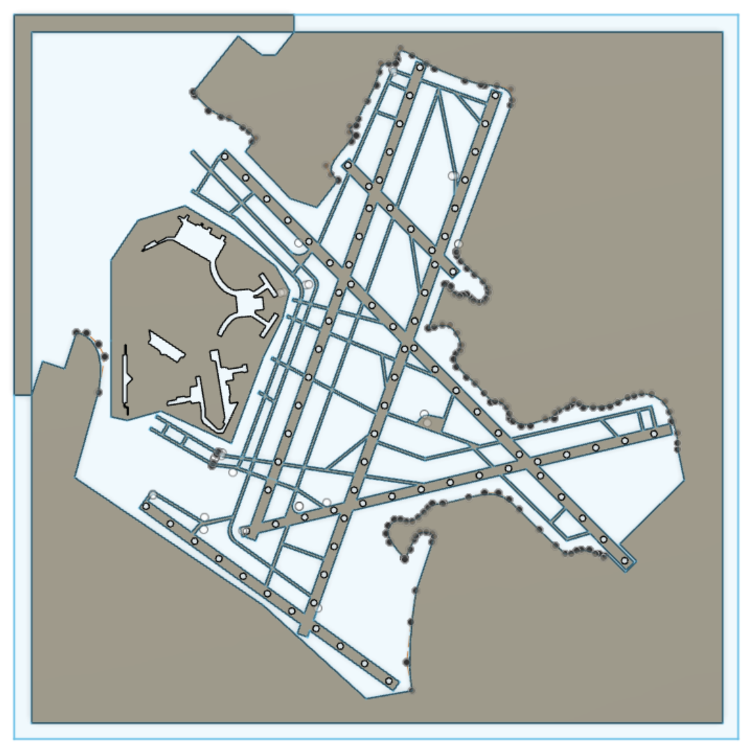
There were a few changes I wanted to make from the first version of my airport outline cardboard layer. First, I cleaned up the taxiway lines closest to the terminals, as I accidentally left out their interior outlines were missing from the initial engraving. I also deleted the outlines of the roads around the terminals, since they detracted from the runways and looked messy running in between the buildings.
Finally, I added the footprints of the buildings, since I didn't want to guess the locations of the terminals when I glued them down onto my final project to my airport outline. I had CADed these buildings in a separate file, so I imported them into my airport outline file by 1) right clicking on the building file, 2) "Insert into Current Design", and then 3) using Combine with cutting to get the outline shapes into my airport outline. I had originally tried to import the sketches themselves, but since I needed 3D bodies for the dxf plug-in to work, and I had both files as bodies anyway, this approach worked perfectly fine. I ended up with different extrusions for the dxf plug-in to work with, which would've required me to align them manually in Corel. <<<< explain alignment better >>>>>>>>>>>>>

Spoiler alert: attempting to align these pieces didn't work at all. The plug-in accounts for kerf, so the dxf outlines didn't fit together perfectly. I drew a circle around the buildings to create extrusions similar to my initial runway outline verison. To quote my notes once again: "I played myself."
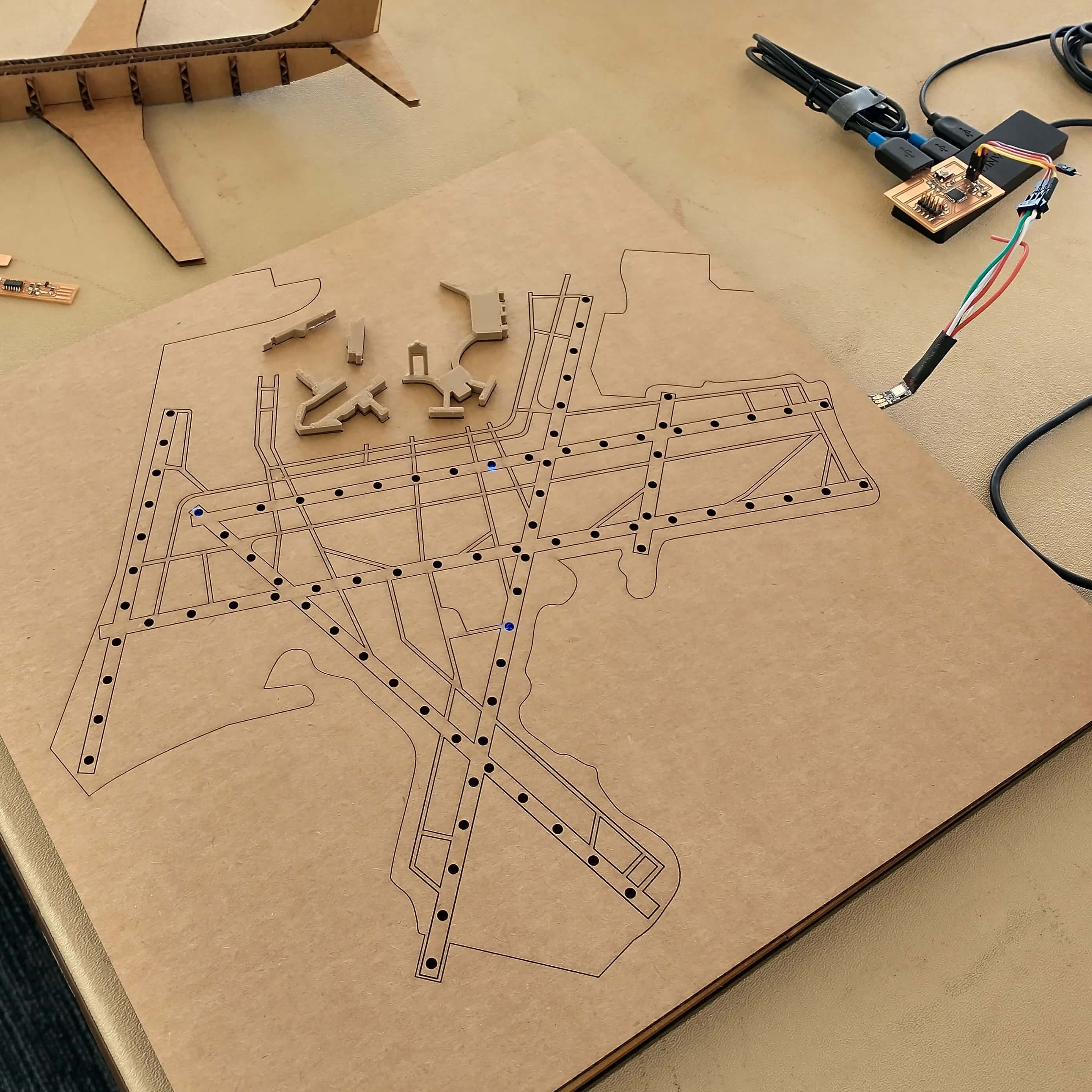
The major change I'd wanted to make was to add holes in the airport outline for the light from the LEDs to shine through - indicating plane location without the LED strips being visible.
I spent some time measuring LEDs with a caliper. After removing outliers and averaging, I obtained the following measurements:
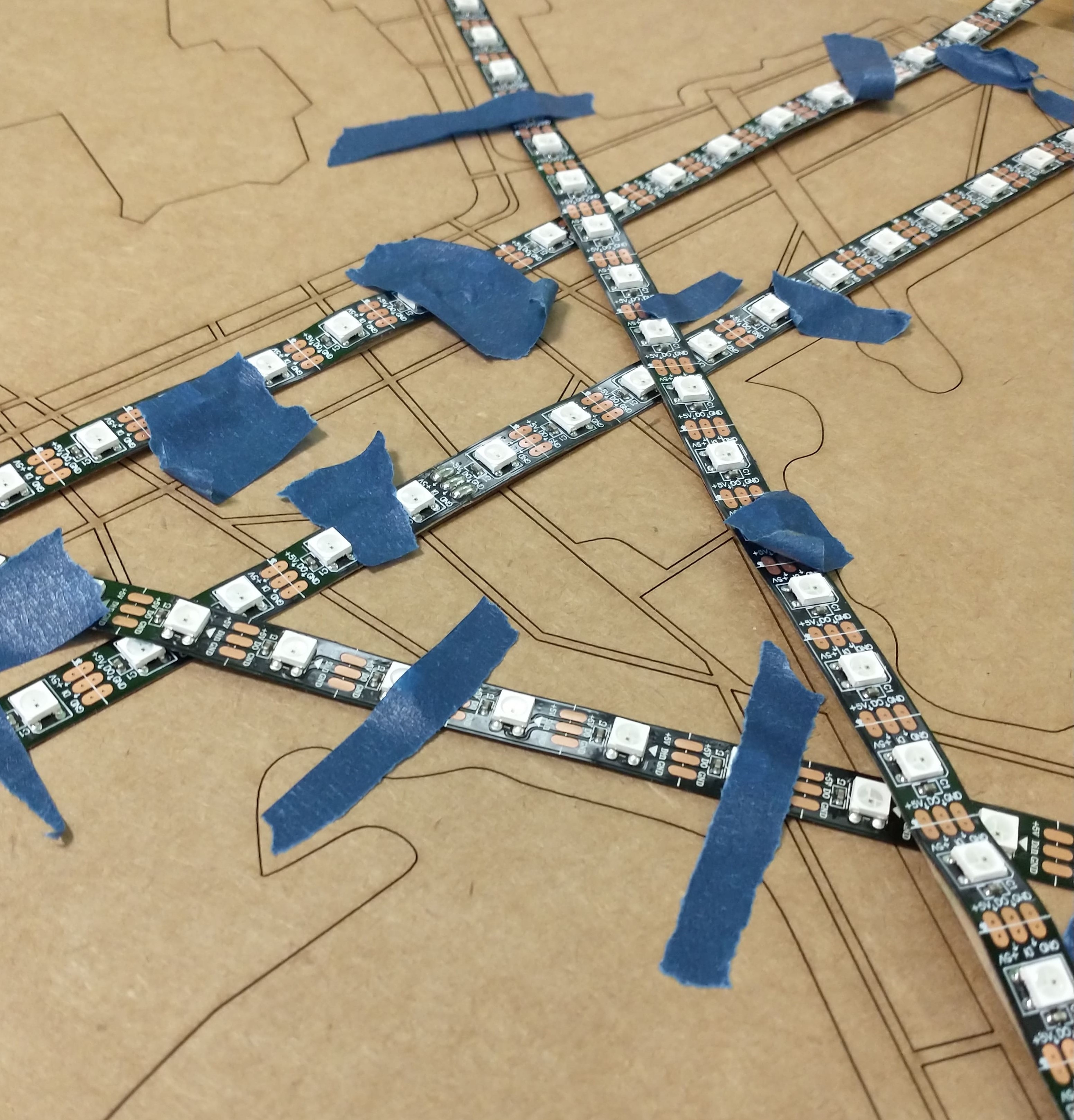
I lined up all the LED strips onto the cardboard piece I laser cut previously, in order to determine where the LEDs should begin on each. It turns out that lining up the white squares with the very edge of the runways was the only way to cover the entire length of each runway without causing LEDs to overlap at runway intersections; the center of first LED hole thus needs to be 2.46 mm from the start of the runway. Runway 33R was the exception, as it needed a 5.75 mm offset to be able to comfortably cross Runways 22L and 22R. (I later changed this back to match the rest of the runways to fit one more LED onto Runway 33R.)
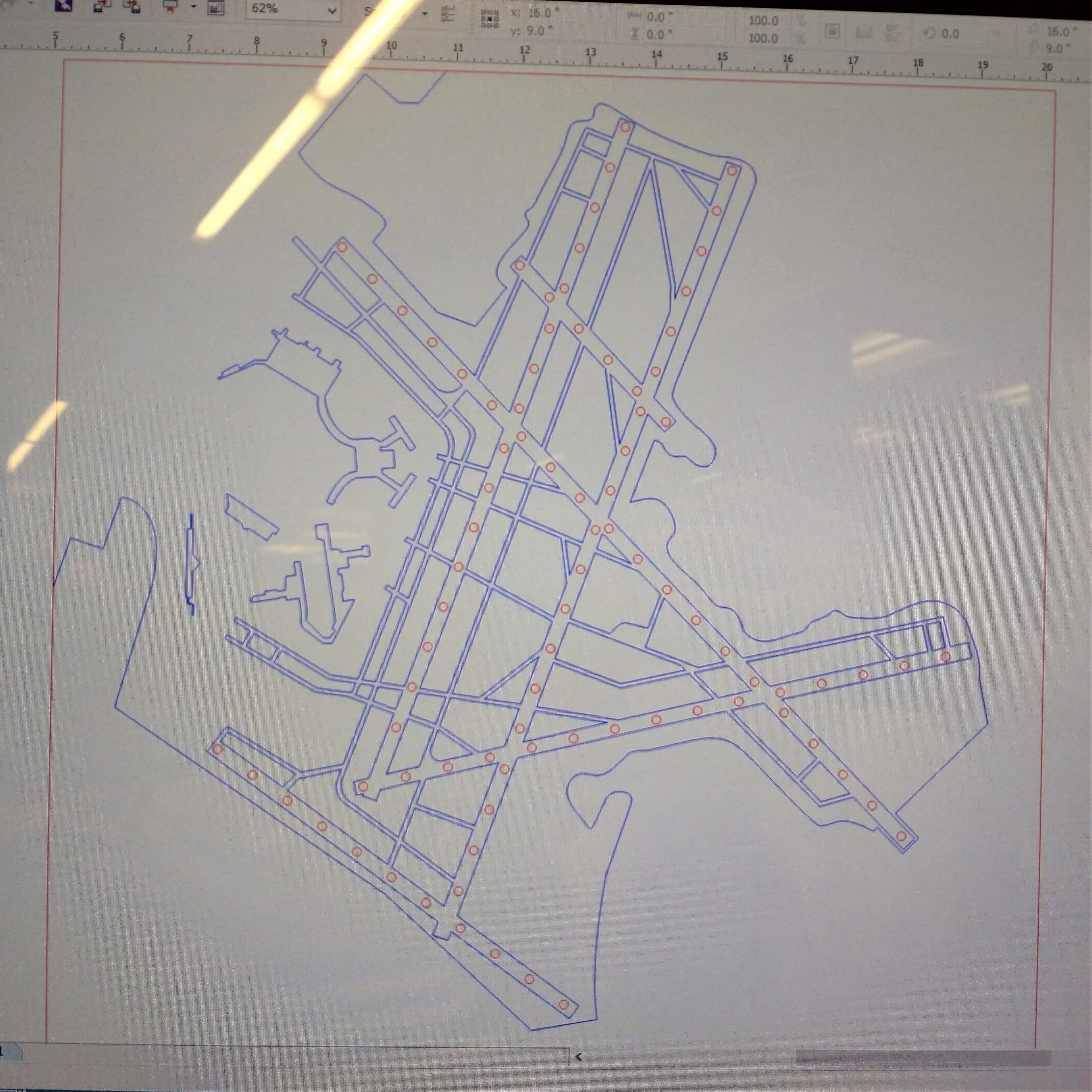
With these measurements, I used sketched out circles in my airport outline CAD and used Rectangular Pattern to propogate the holes down the length of the runway. The number of holes in each runway corresponds to the number of lights along the section of LED strip that covered the entire length of each runway. At some point in this process, I realized that I had forgotten that planes can fly, so I could fit more LEDs onto the runway than I had initially planned.
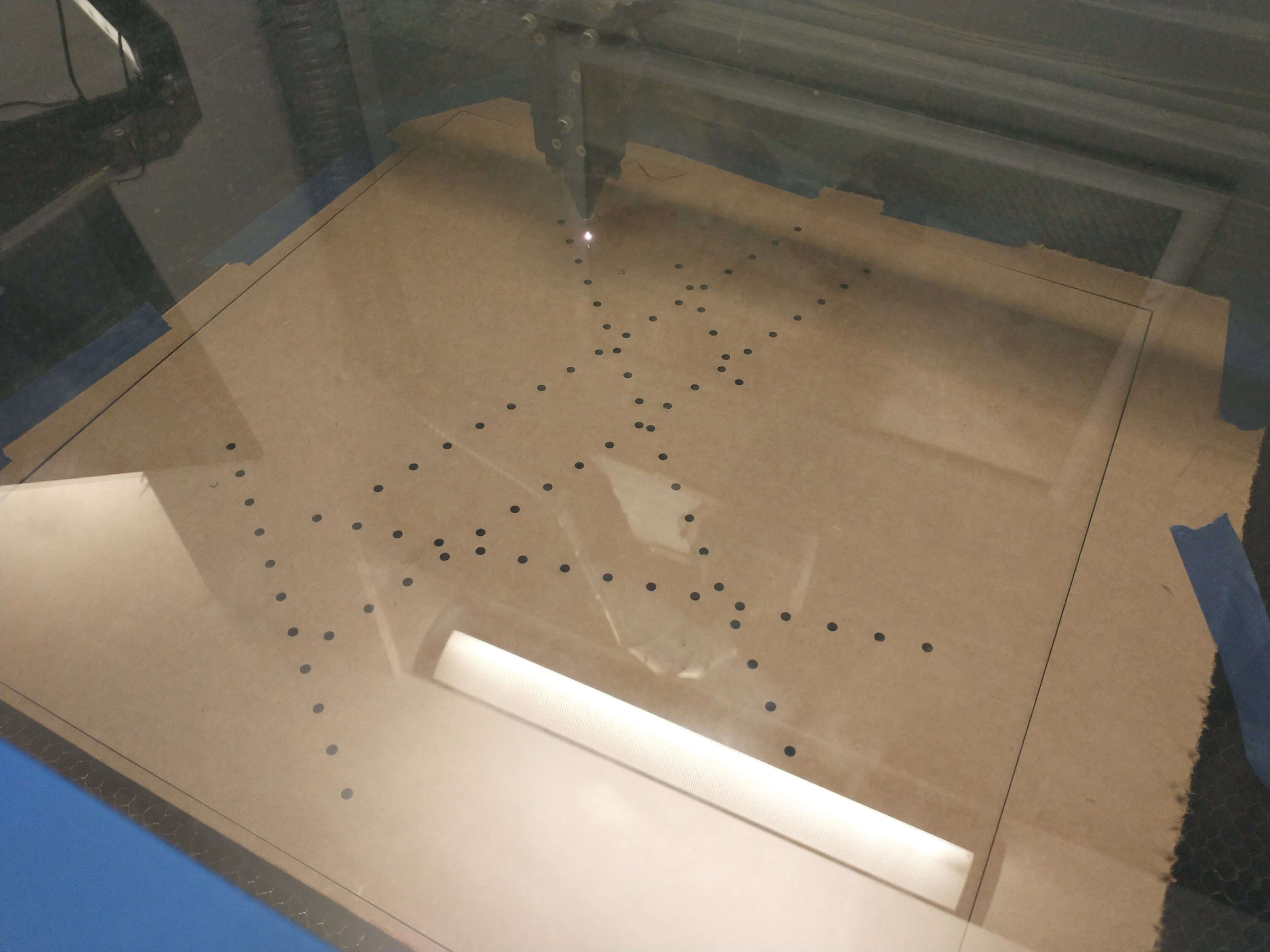
I now had the locations of all the holes I wanted, and I now had to decide how large to make the holes, so I decided to laser cut a small section of the airport to test out different hole sizes with the LEDs. I created holes of 3 diameters: 3 mm on Runway 22R, 3.5 mm on Runway 33R, and 4 mm on Runway 22L.
I then laser cut the piece out of cardboard. Corel allows you to select multiple parts at once via Shift+click - which I used to set all the hole outlines to red, for the laser cutter to cut through instead of engrave. Selecting every hole in the final airport outline is going to be fun.
Finally, I taped an LED strip to the back and experimented with the 3 runways and with different LED brightness settings. The results were:

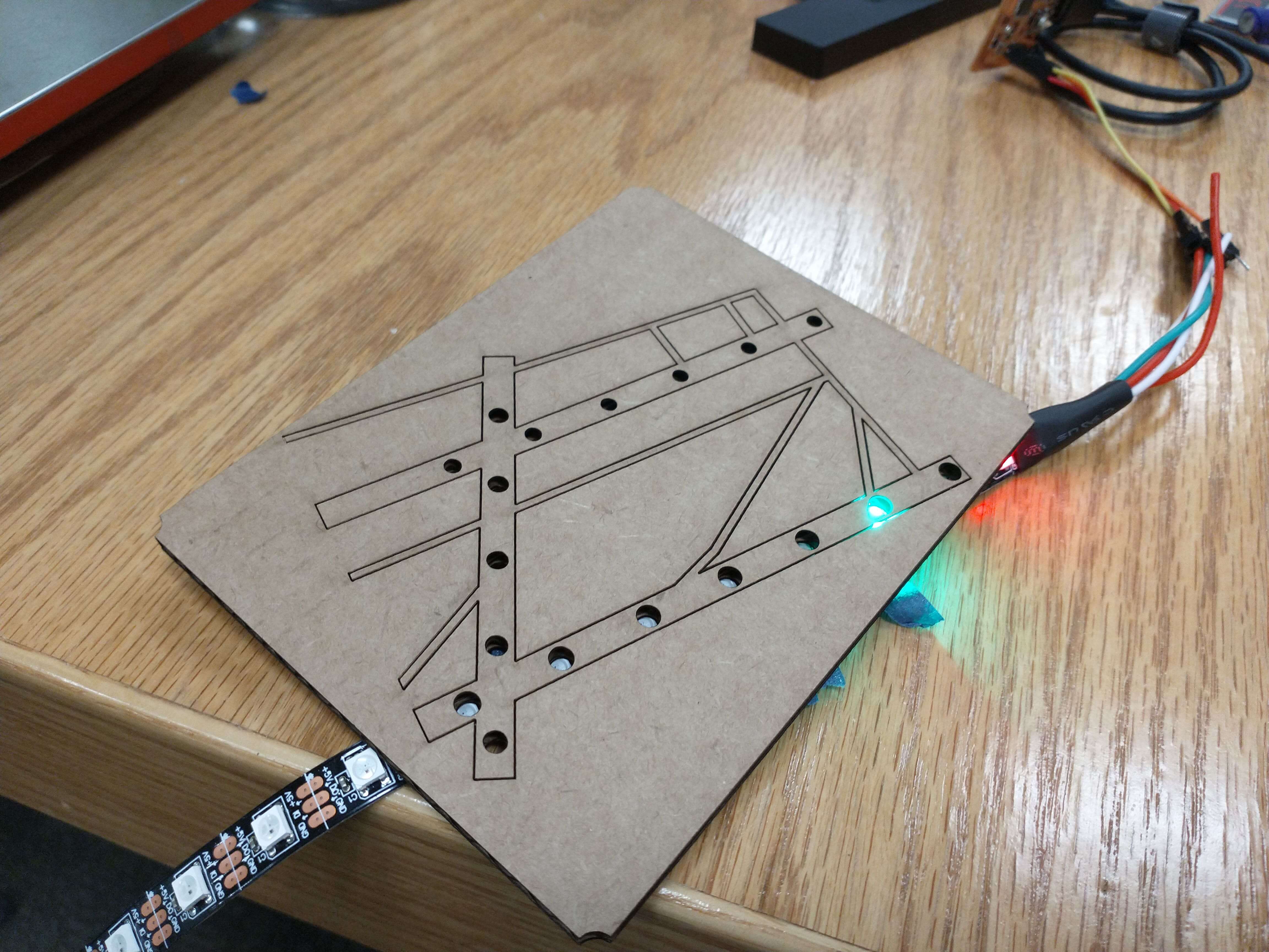
I chose to go with 3.5 mm holes and added LED holes to all six runways. Now my airport outline was ready to be cut!
After manually aligning the dxf files in Corel as usual, I laser cut the final outline on cardboard, which took about 9 min 15 sec. One small piece (bordered by 4 taxiways) came free, which I hotglued back on.
I then decided to give the balsa wood a try, even though I would need two pieces. I laser cut the wood pieces into 8 inch by 24 inches, so each piece would equally half the airport outline (which involved lining up the outline design corrspondingly in the laser cutter). I chose to laser cut this piece without LED holes so I could first examine whether I preferred the one-piece cardboard outline or two-piece wood outline. I used masking tape and superglue to join the two wood pieces.

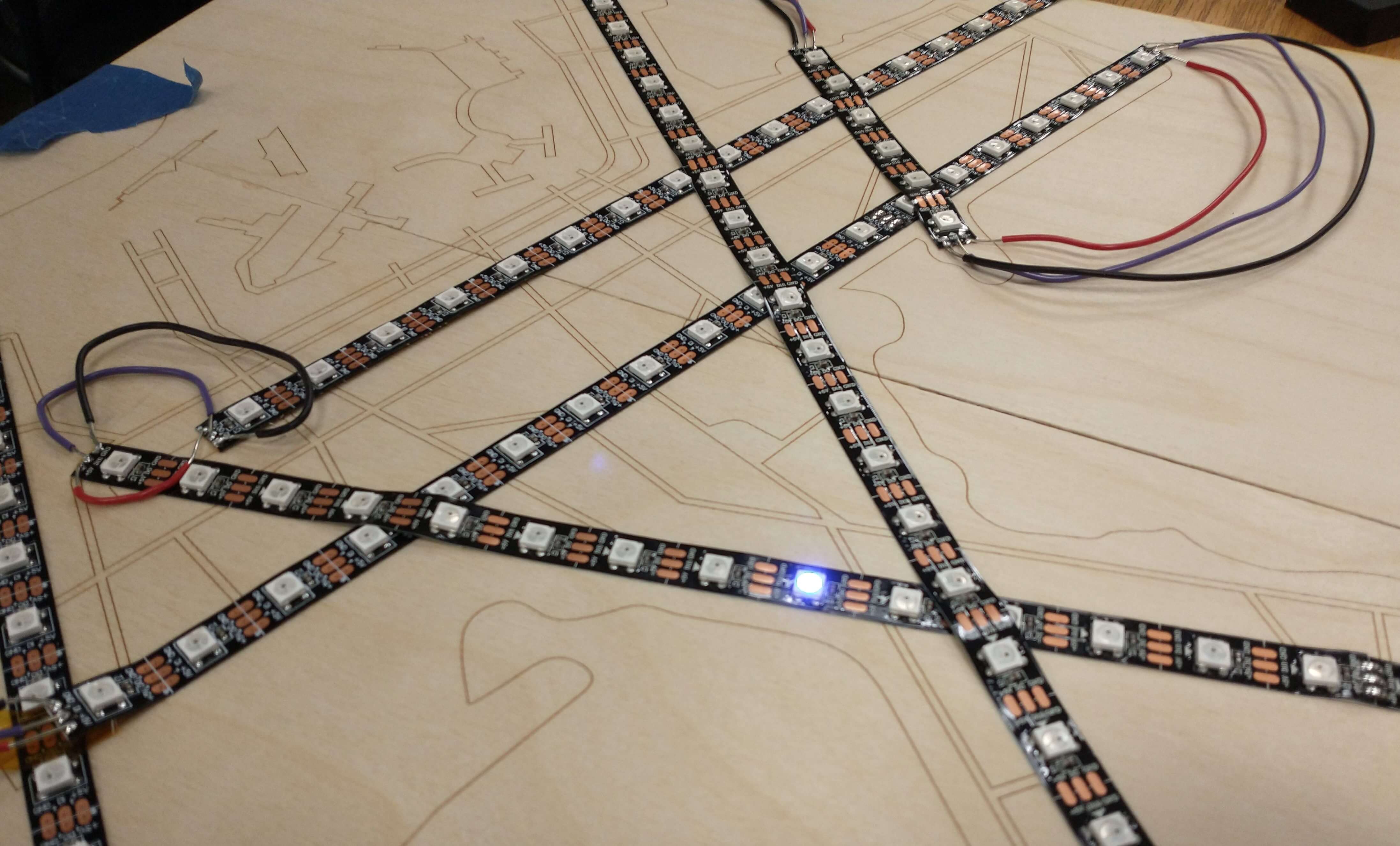
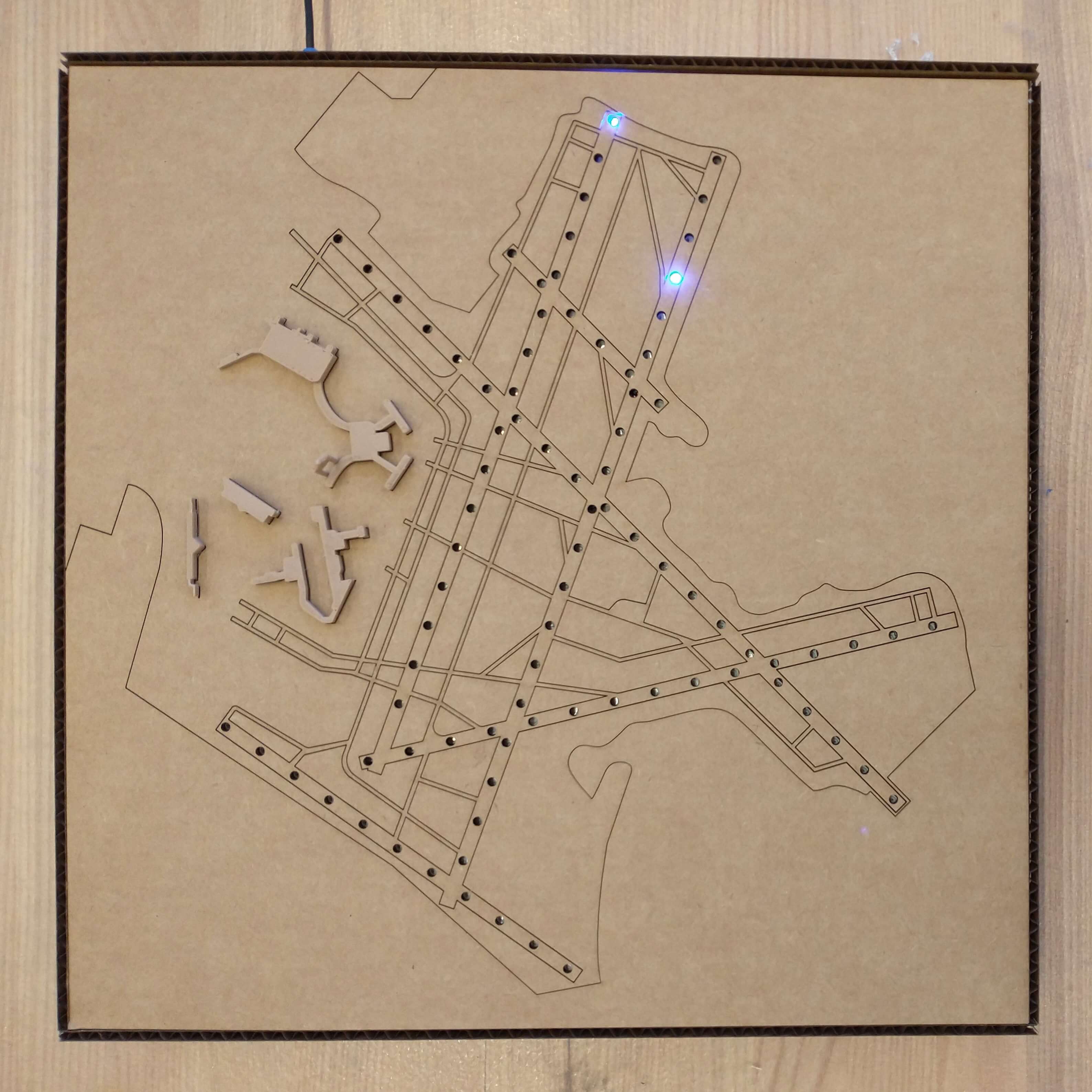
The time had finally come for me to assemble the parts of my final project into one unit. The LED strips had an adhesive on the back and could be attached to the wooden airport outline like a sticker. I decided on an order in which to wire the runways together (taking into account the directionality of the LED strips), taped down the LED strips onto the balsa wood (using masking tape), then one by one, and stuck the LED strips into their final positions. I stuck the strips down such that the runways that were overlapped by other runways were placed first onto the wood. To keep the LED strips in the exact spot I wanted them, I used an adhesion alignment process similar to placing screen protectors onto phones. Throughout this process, I used the top airport outline layer to double check that the LEDs were lined up to the holes.
Anthony found me some nice flexible wire (and had the foresight to offer me three different colors.) Red corresponds to VCC, black to GND, and purple to the data line. I cut and stripped pieces of wire to the appropriate lengths between runways then soldered the wires to the LED strips. I hot glued over the solder joints (at Alec's recommenation), to keep them from snapping, and glued the wires down to the wood as well. I also used a bit of capton tape to prevent the end of one LED strip from overlapping the connections of another strip. Finally, I updated my code - particularly the indexing of the runways, to reflect the order in which the runways are wired - and tested everything out by lighting up all 89 LEDs up one after another.

Since I initially laser cut my top cardboard airport outline to test the design's dimensions, I was originally thinking of using acrylic for the top layer. Anthony still had a large piece of dark acrylic left, which I bandsawed down to an appropriate size, then used to laser cut my airport outline. The acrylic transmitted the LEDs' light sufficiently, but the LED strips were still visible underneath. I decided that I liked the cardboard's aesthetic more, particularly how its color fit the terminals' color. I now use the acrylic piece to faciliate transport of the other layers and to keep the layers clean.
Once I decided on the material for the top layer of my final project, I hotglued my terminal buildings onto the cardboard, placed the layers on top of each other, and plugged in the PCB for a functioning KBOS model!
My project currently consists of a piece of cardboard stacked on top of a piece of wood stacked on top of a piece of acrylic, with wires sticking out to the side plugged into a PCB plugged into a USB cord. Needless to say, this is not yet the single, cleanly packaged final version I had in mind.
So I started making a box. The airport outline and LED layers need to fit snugly within the box and be propped up so that there is sufficient space underneath for any wires, PCBs, and other electronics that I had and may add in the future. The box needs to be easily assembled (for my sanity, as I was quite tired at this point), easily opened and closed to make any modifications to the electronics, easily plugged in, and account for wires in between layers. Finally, I want to be able to display this project both horizontally (i.e. on my desk) and vertically (i.e. on a bookshelf).
My initial vision was to make this container using acrylic. Carrying the current state of my final project around, however, has informed me that acrylic is non-negligibly heavy, and I quite like the cardboard aesthetic, so I decided to first make this box in cardboard to test dimensions and appearance, then I'd potentially make it out of acrylic if desired.
Using a caliper to obtain the necessary measurements, I drew a sketch of the overall design then sat down to CAD. I parametarized my CAD file to account for any potential future changes in material or distance between layers.
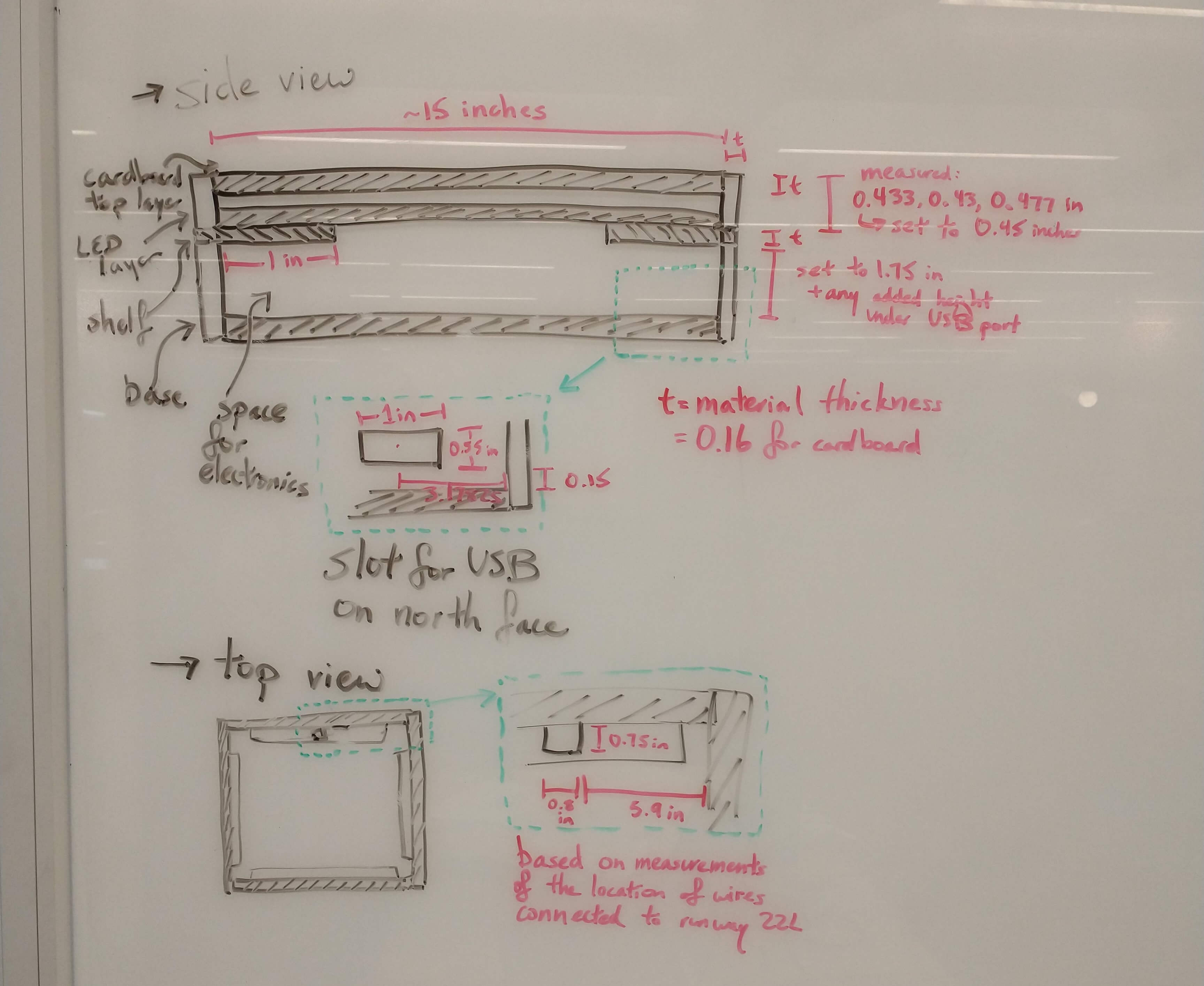
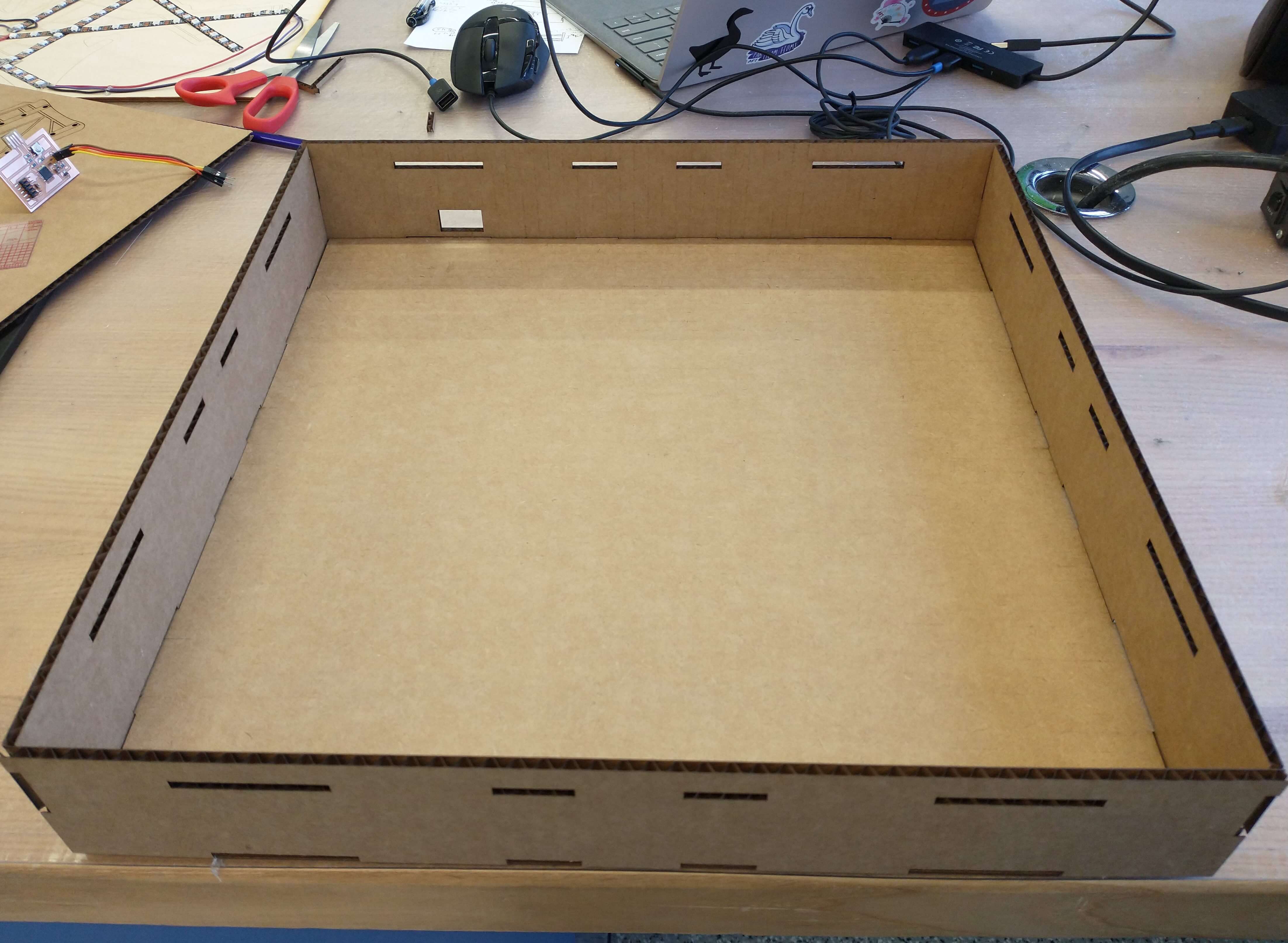
I started sketching out and extruding the lower right corner of the box first. To fit the walls and base together, I added finger joints (most of which are 2 inches long along the base and 1 inch long between walls). I took this bottom right quadrant of the box and mirrored it in the x and y directions to create a full box.


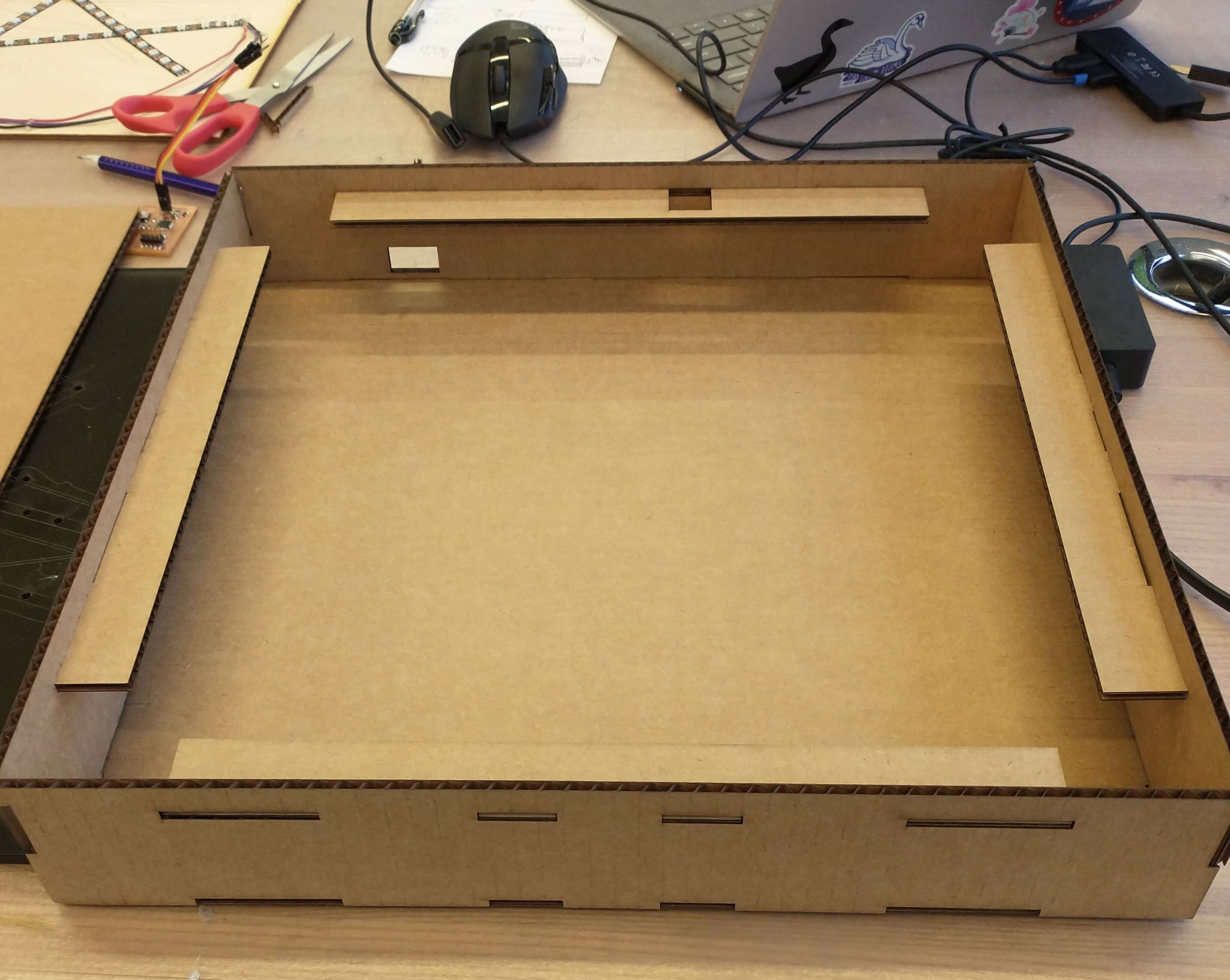
I then added a slot to plug the PCB into the USB connector. I then remembered I needed to make the shelves to hold up the airport outline and LED layers - and the slots in the walls to hold the shelves in. Because I had already used Mirror and didn't want to have to redo my USB slot, I duplicated my retangles that I'd made for the finger joints rectangular prisms, moved them up to the appropriate height, and cut through the walls using Extrude.

I then sketched out and extruded the horizontal and vertical shelves. Because the left and right shelves were identical, I didn't bother creating two of those, as I could simply load the same dxf file twice when laser cutting. The top and bottom shelves needed to be different, however, since the top shelf needed an opening to connect the LEDs to the PCB; thankfully, adding this hole still keeps the top shelf in one piece.
And I was done with the box design! I exported all the pieces, using the usual plug-in to convert bodies in Fusion to dxf files, as well as the usual 0.15 mm kerf.

Laser cutting the pieces out went fairly smoothly. All the pieces manage to fit onto one 18 inch by 30 inch sheet of cardboard. As usual, the most irritating part of the process was cutting down a piece of cardboard to fit onto the machine bed without missing any material for my parts.
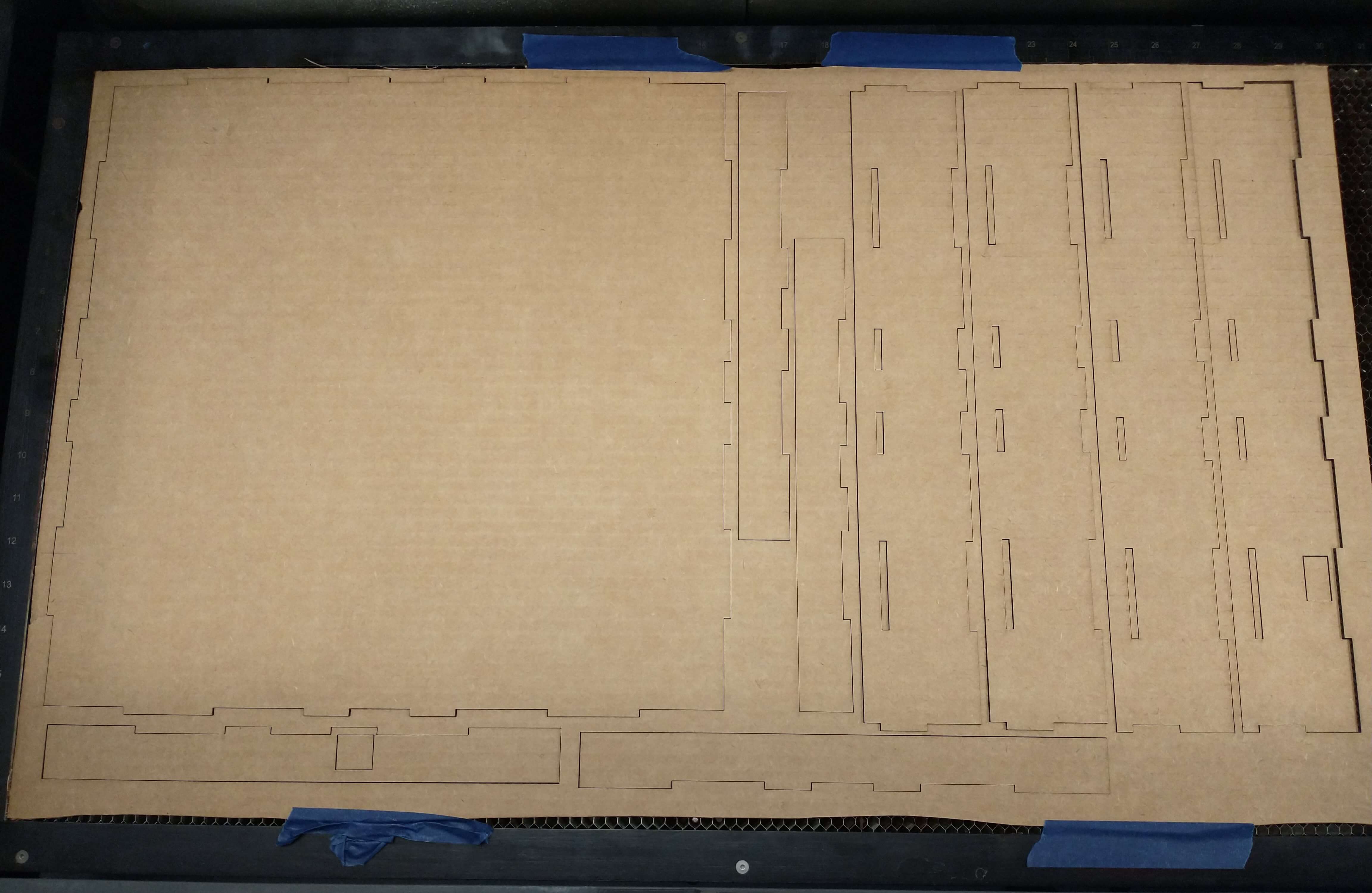
The base and the walls fit together perfectly. However the shelves did not fit into their slots; I had forgotten to cut the slots a little wider than the thickness of the cardboard. Luckily, I had a stroke of genius - I simply manually compressed the tenons of the cardboard so they now fit perfectly in the walls. Once I verified that all the pieces fit together (and with my electronics and airport layers!), I began hot glueing the pieces together.
Hot glueing was not quite as straightforward as I thought. I had to ensure the walls and the base were snugly bound together but not so closely as to prevent the airport outline and LED layers from fitting. I also started applying glue between walls above the shelves, and the glue's thickness prevented the top layers from sitting comfortably in the box corners, so I used a box cutter to cut away the excess glue.
<<<<<<<<<<<<<<<<<<<<<<<<< photos of the gluing?? >>>>>>>>>>>>>>>>>>>>>>>>>Finally, once I finished the initial glueing of all the parts, and everything fit together perfectly, I went through all the finger joints and added more hot glue in the corners.
<<<< PHOTO OF HOT GLUEING FINGER JOINTS >>>>>>>>>>>>>>>>>>>>>>>>Because the top layers are meant to fit snugly within the walls of the box, removing the layers is nontrivial. I use Terminal A to tug on the top cardboard layer. The LED wooden layer, however, didn't have such a feature, so I hotglued on a square of wood to serve the same purpose.
<<<<<<<<<<<<<<<< PHOTOS OF THE DIFFERENT LAYERS >>>>>>>>>>>>>>>And it's done!
And it's beautiful! And it works!
The CAD files can be found here.
My plans for this project in the future primarily consist of adding more features.
Massive thank you to Anthony, Harrison, and the entire EECS section for being my HTMAA family and getting me through the semester. Thanks to the entire teaching staff for their fun recitations and assistance, as well as to all the students in the class; I've been thoroughly impressed by all the ideas and skills each person has. Thank you to Laura for encouraging me to sign up for the class and to Jeremy and Cambridge Hackspace for getting me excited about fabrication. And of course, thank you to Neil for giving me this opportunity.
And another thank you to Anthony again for his invaluable patience, kindness, and assistance with my final project - from ordering and providing materials (and food!), hosting (very) long office hours to keep EDS open, helping me troubleshoot and debug, and more.