Since my final project is aviation-related, I decided to CAD a plane - a Boeing 737. The 737 is one that I've been on multiple times, is manufactured in an impressive factory in Seattle that I loved visiting, and has blueprints and airfoil shapes are available online.
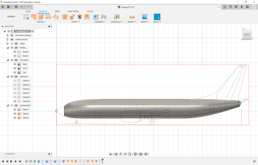
Alfonso recommended that I learn how to use the beginner-friendly Fusion 360 and make a Lego, and I referenced the first four videos of this set of tutorial videos to make my plane. I started off by downloading the top, front, and side blueprints of the 737 and imported them into Fusion as canvases. I aligned them and resized them to match the actual dimensions of a Boeing 737 (to be scaled down to my desired dimensions afterwards - probably not the best approach, but I cut myself some slack as this was my first time CADing).
Once setup was complete, I began modeling the fuselage - the body of the airplane. I created a cylindrical form (the purple option under Create in the Solid tab) by estimating a circular cross-section of the fuselage and creating 4 face heights along the fuselage length. Editing the form allowed me to resize the cross-section (since a plane is not perfectly circular) and to extrude new faces. I molded these faces to the fuselage's decreasing cross-sectional radius towards the nose and tail, making sure to adjust the top-down scaling and side scaling each time I extruded.
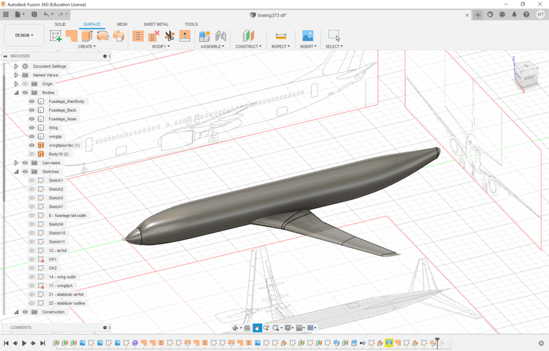
I outlined the nose of the plane by drawing a sketch on the front of the fuselage, using Project and Control Point Spline, then used the Loft function to turn the sketch into a body. The tip of the tail was created with the same method.
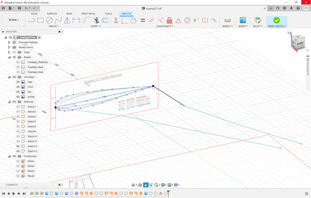
Next up were the wings - or rather, just the left wing, since the plane is symmetrical. I added an airfoil diagram as a canvas for reference. I outlined the root airfoil using Control Point Spline. Since the wings are at a dihedral angle and are not parallel to the ground, I created a plane (the surface, not the aircraft) at a 5 degree dihedral angle through the chord (the center line) of the airfoil. On that plane, I sketched out the top-down outline of the wing's shape and then used the Sweep function to create a 3D wing. I had to trim the resulting edge of the wing and added winglets (via the same process as the fuselage nose). The winglets turned out a bit suspicious-looking, which Alfonso instantly noticed when I showed him my final CAD, and no one else knows enough about planes to tell, so it's fine.

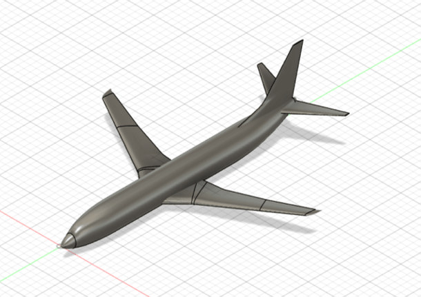
The left half of the empennage - the vertical rudder and the horizontal stabilizer that make up the tail assembly of an aircraft - was made with the same approach as the wings, though I didn't bother with making tips. The horizontal stabilizer had a 6 degree dihedral angle. I mirrored these left halves (as well as the left wing I'd previously made) to create a symmetrical, full aircraft.
And here's the final outcome!
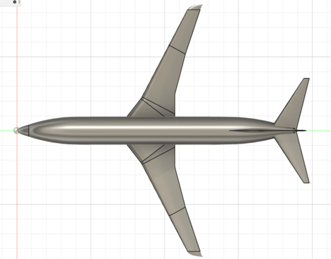
The CAD file can be found here (which includes Week 2). Applicable bodies are: Fuselage_MainBody, Fuselage_Back, Fuselage_Nose, Wing, Wingtip, Stabilizer, Rudder1, Rudder 2, and Wingtip Right.
For future projects, I'd definitely name every sketch, plane, and body in the project - and clean up the organization of all the parts. I'd also like to learn how to CAD objects that aren't symmetrical (like animals).
Thanks to Alfonso for his advice on how to get started and to the TEX - Design & Engineering Youtube channel for guiding me through the process and keeping me from feeling completely lost.