I thought up a few options for this week.
A compilation of definitions for me to finally solidly remember:
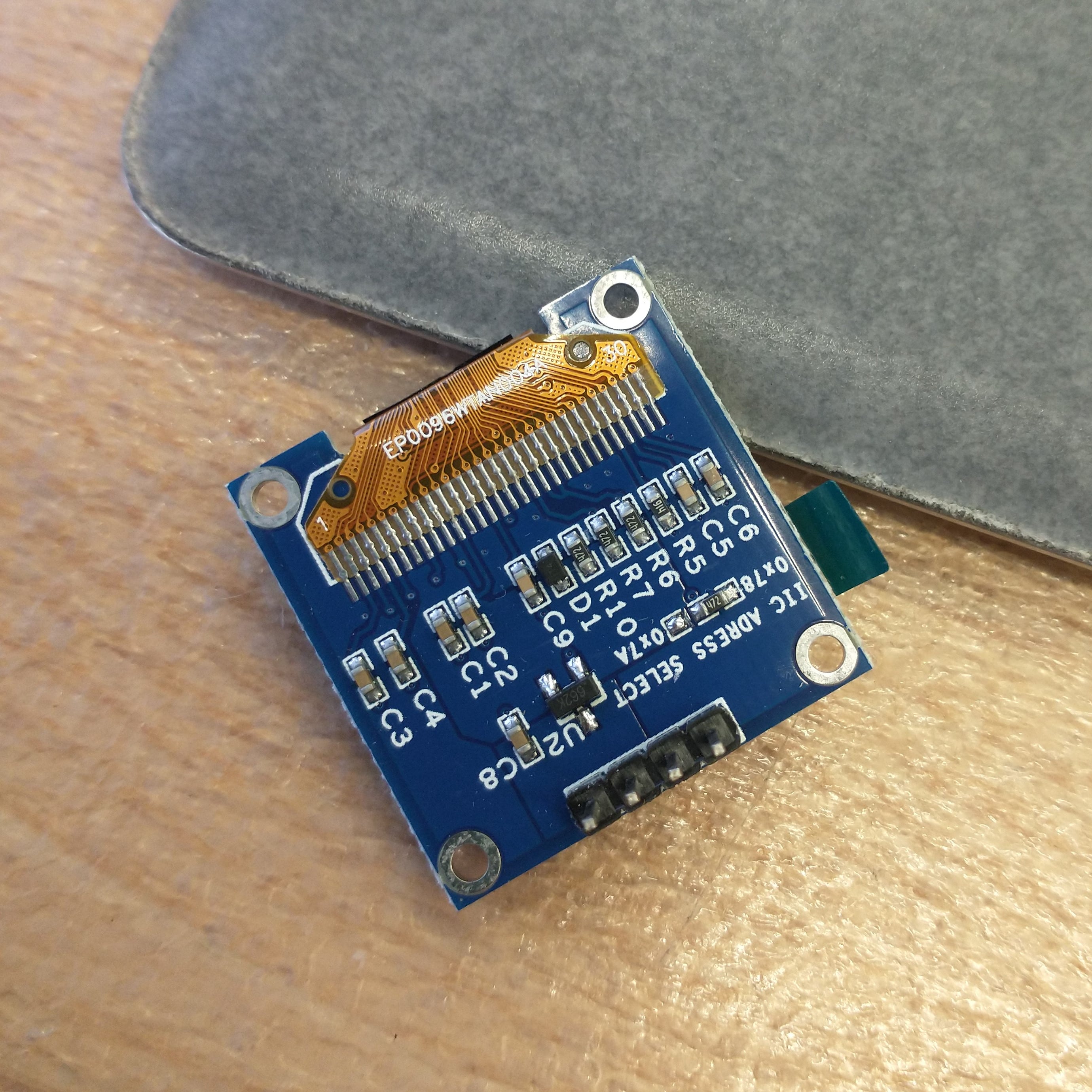
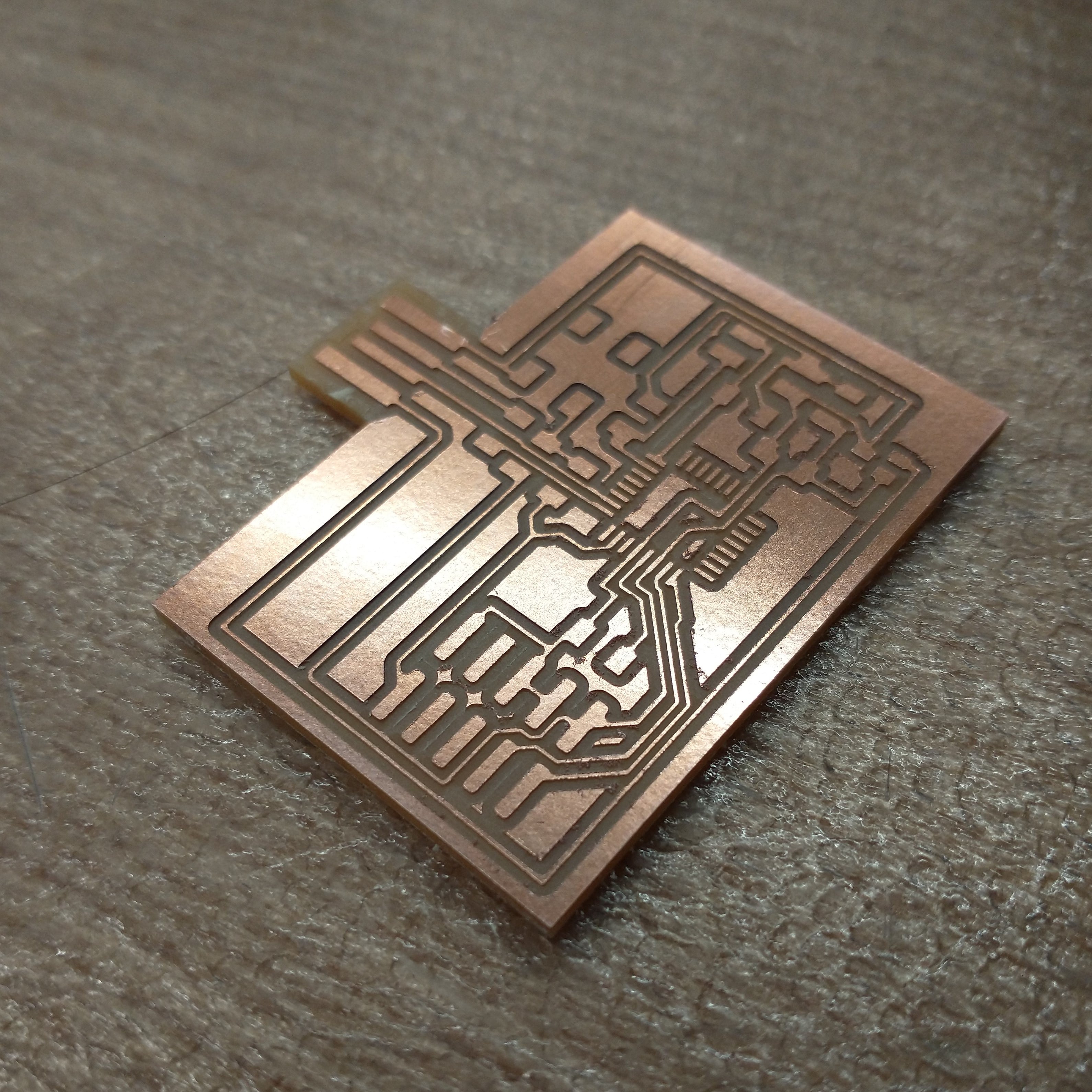
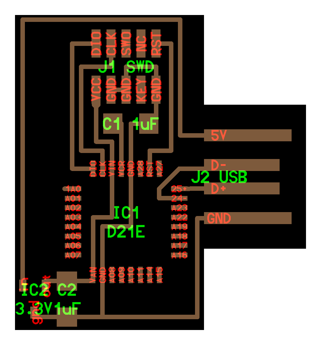
I used Neil's hello.SSD1306.45 board as reference for what goes into a board with an OLED display. There's no 1x4 connector in the Eagle library, so I'11 just use a 2x2 connector and use wires to connect the board with the OLED display. The rest would be the same as Neil's except everything changes. I got rid of one of the capacitors, replaced the FTDI with a USB port, replaced the 2x3 connector with a 2x5 as usual, and added a voltage resistor and button.
Part Names in Eagle:
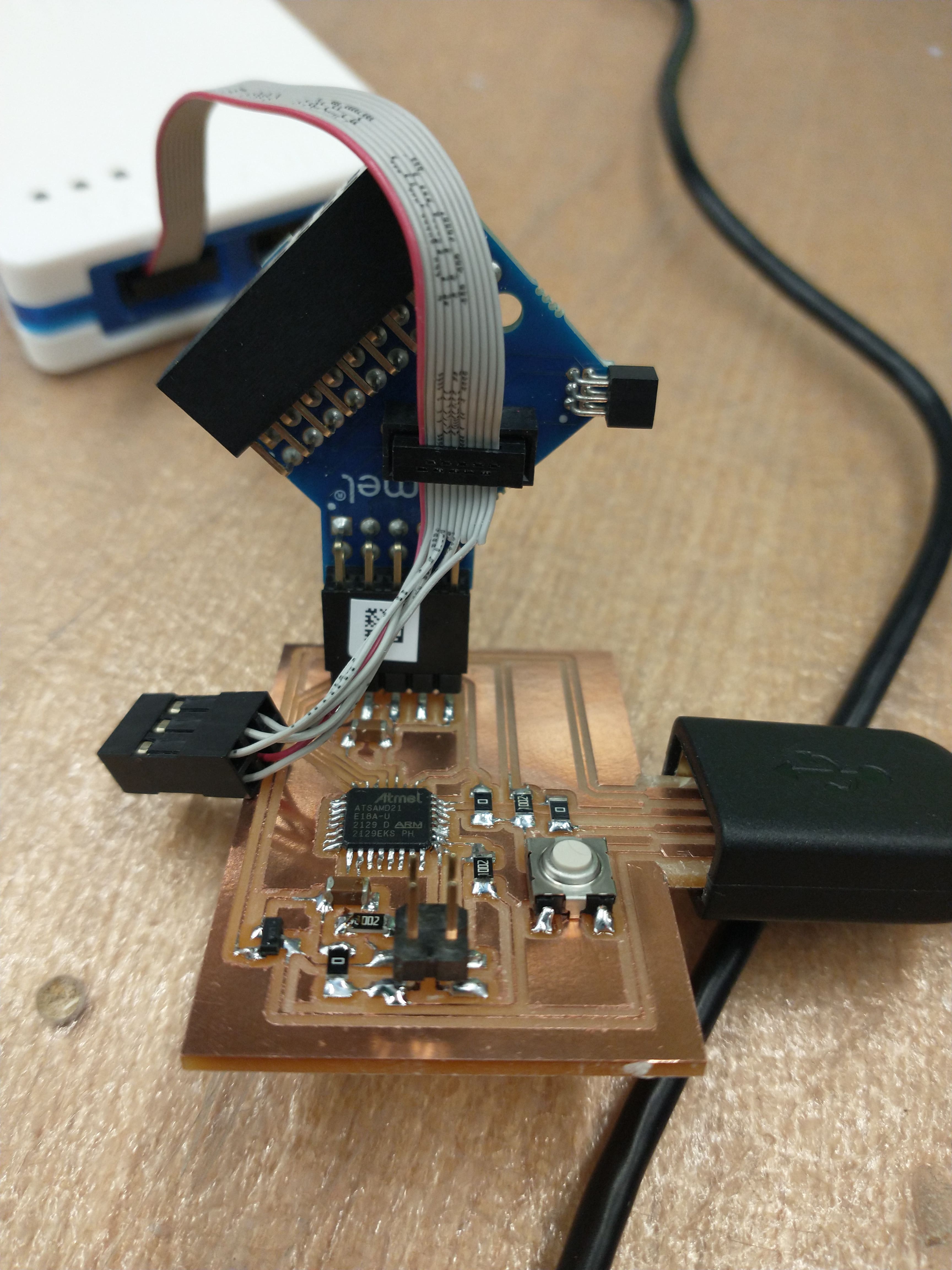
Learning how to use a new microcontroller took a bit of time. For one, I was thrown off by the fact that there were VDDCORE, VDDIN, and VDDANA options. VDDCORE is connected with a capacitor to ground, while VDDIN and VDDANA just connect to the voltage regulator. I referenced Neil's hello.D21E.echo board to determine the 2x5 pin and some of the SAMD21E routings. One of Jake's schematics was another nice resource to refer to, and I checked the SAMD21E datasheet to figure out which pins were GND.
Although the SAMD21E datasheet says which pins are for I2C, it does not specify which pins on the microcontroller could be used for SDA and SCL. Lingdong kindly posed a bunch of documentation describing his efforts with the OLED display, which said that the pin grouping options were PA16+PA17 and PA08+PA09. Unfortunately it was still a tad unclear which were SDA and SCL, so I put my faith in Lingdong being consistent in his documentation - which was backed up by his code, as well as the fact that his documentation is always very well done. (Lingdong, if you're reading this, the entirety of the EECS section would love to be friends with you.)
Both Lingdong and Anthony recommended adding a button to reset the microcontroller, which of course means adding a pullup resistor (done properly this time!). Anthony's electronics primer was very helpful, and I actually understand a lot more of the primer than I did when Anthony first wrote it weeks ago.
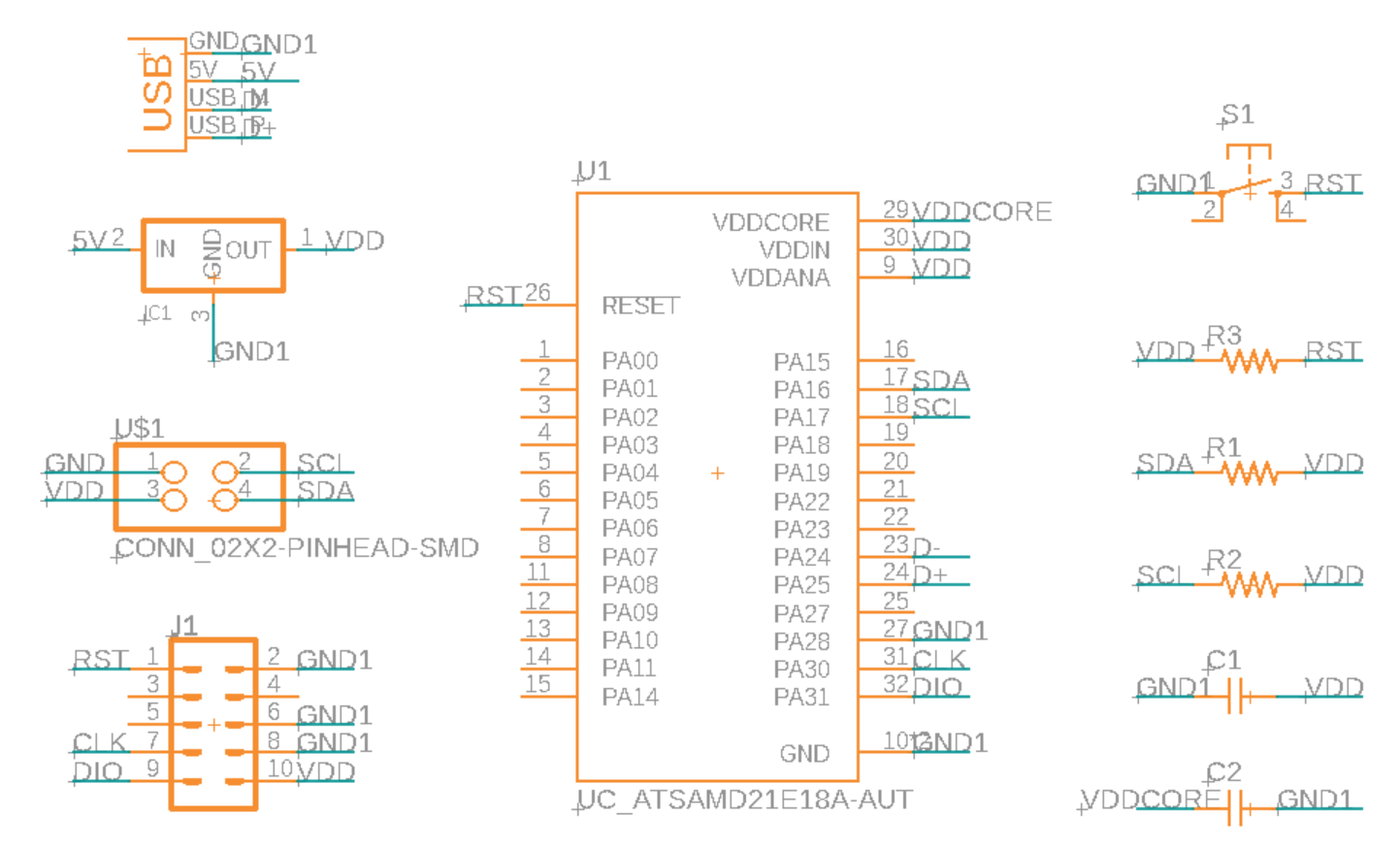
A few changes I made after I started routing the board included adding jumper resistors (only three this time!), and correcting one of the ground pins on the D21E. Turns out the 10*2 GND pin in the schematic corresponds to both PA10 and PA28 ground pins.

There were a number of resistors and capacitors already involved in this board, so I tried using the existing ones as bridges over traces where I could. It is somewhat irritating that D- and D+ on these microcontrollers are in reversed order from what they are on a USB port, so a jumper resistor was required, since I can't fit a trace through the corner of the D21E. I also tried really hard to avoid adding a jumper in the lower left part of the board in order to route the VDD and GND traces. After a lot of attempts made primarily out of stubbornness and spite, I resigned myself to adding a resistor and being frustrated at the order of the pins.
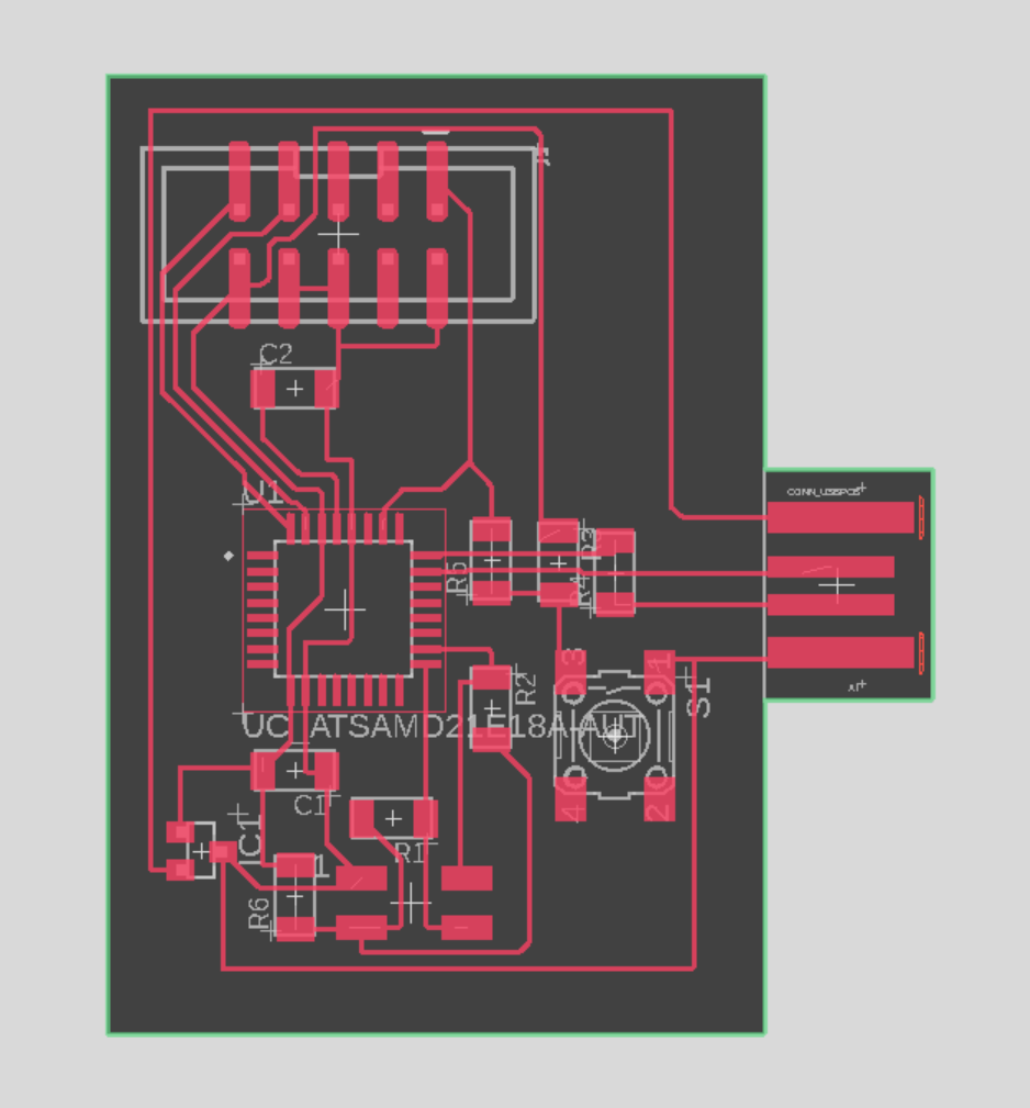
The Eagle files can be found here.
This went smoothly as usual. A list of parts:


I took notes on how to do this this time, which makes up for the fact that this was also the first time one of my boards didn't successfully bootload on the first attempt. So my board may have burned Anthony while he was trying to burn a bootloader on my board (Newton's 3rd Law?). VCC and GND were shorted at first because there was a thin copper piece that connected two traces - a simple fix. To bootload, under the Tools tab in Arduino, set the following:
Adafruit has font and shape options, which I'll probably use in a future week.
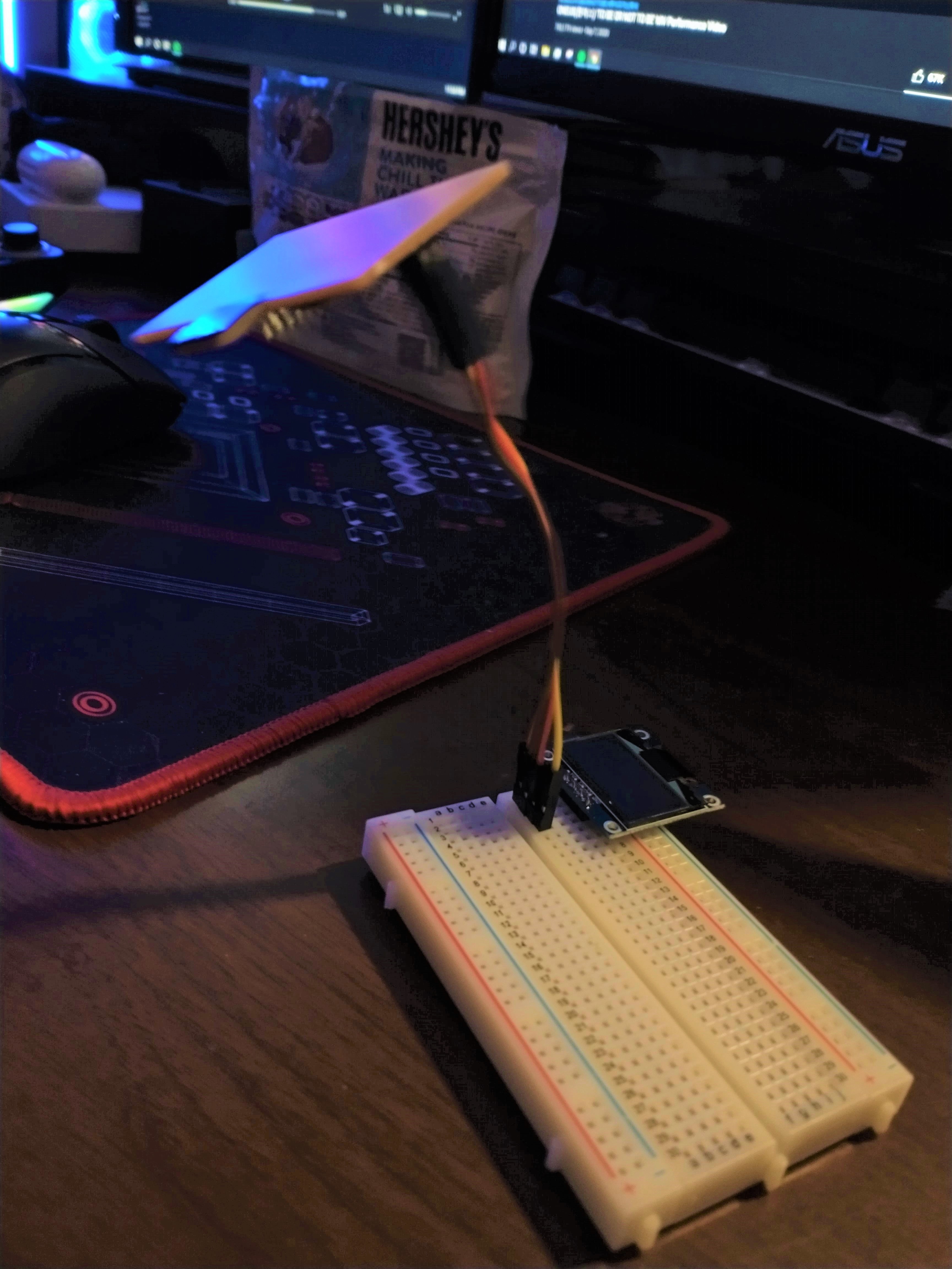
To plug in my board, the order of pins on the 2x2 connector from left to right, top to bottom are: SCL, SDA, GND, VDD. After stuffing my board, going home, and eating dinner, I sat down ready to program my board then promptly realized I had a male to female connector, when what I needed was a female to female connector. My housemates with 6.810 kits, in lieu of the female-female connectors they did not possess, offered me use of a breadboard.
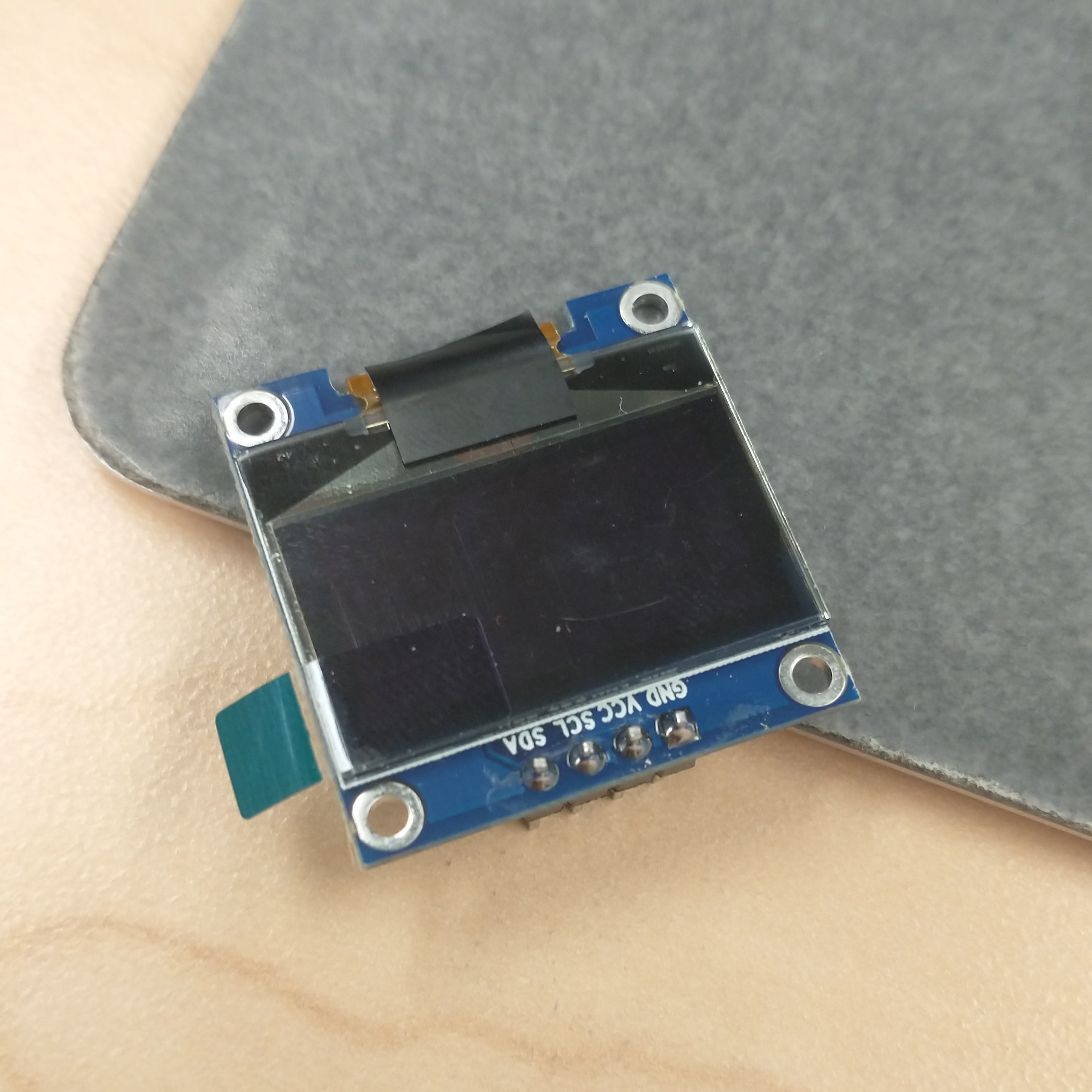
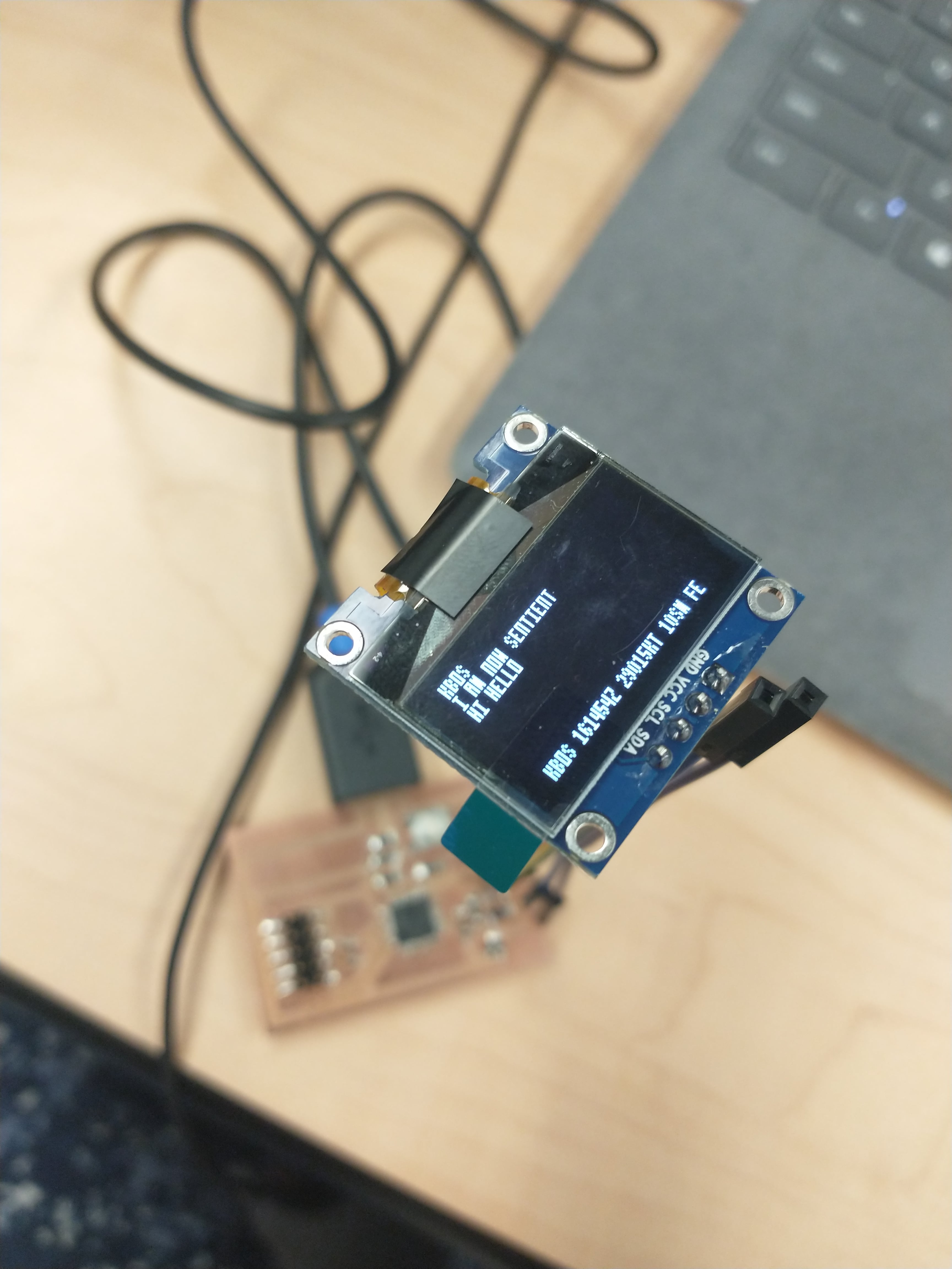
I got the display to light up! Once again, massive thanks to Lingdong for providing documentation. I build my code off of his, as a bit-by-bit sending method seems a bit (haha get it) too much.

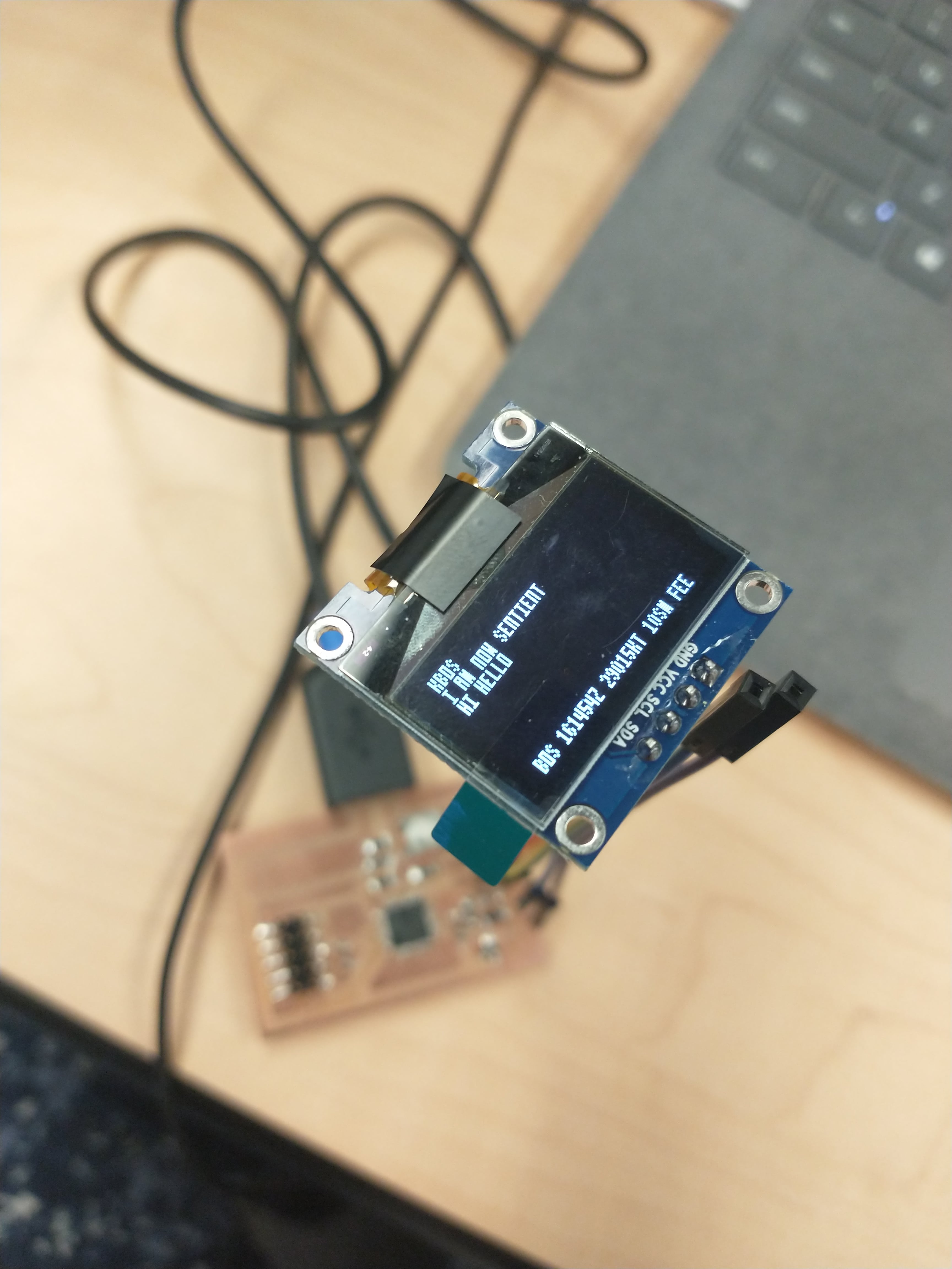
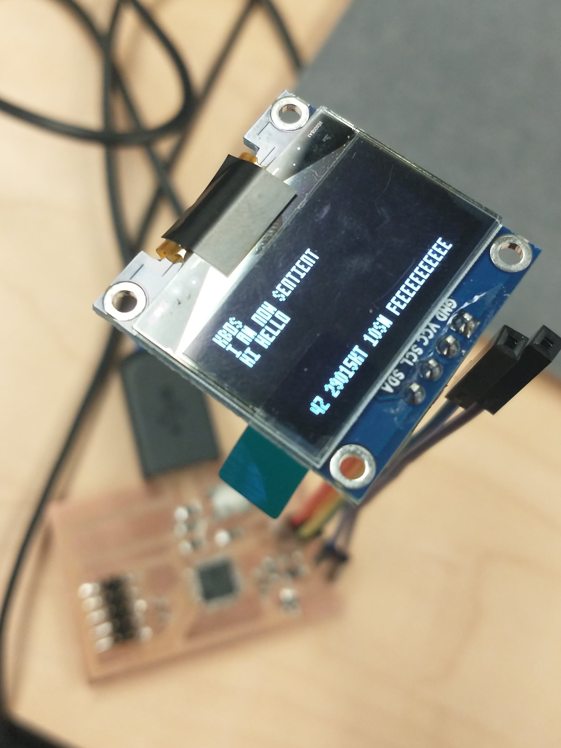
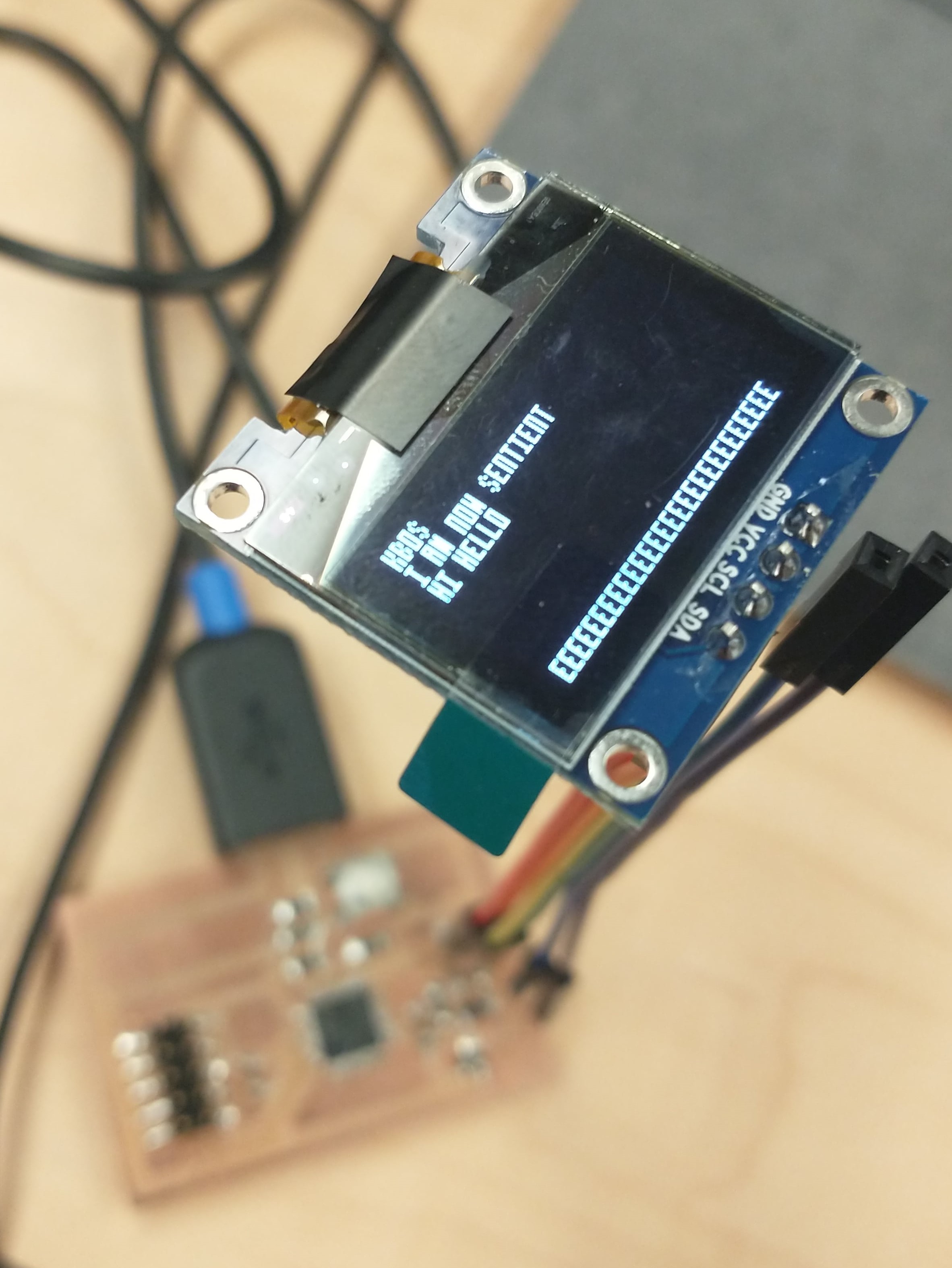
I wanted to try to do some text scrolling with METAR weather information for Boston Logan Airport, as trying to print a series of words longer than what can fit on the screen seems to result in only the centermost characters being displayed.
KBOS METAR Weather at 11/16/21 10:40 AM : KBOS 161454Z 29015KT 10SM FEW050 06/M04 A3002 RMK AO2 SLP164 T00611044 51018
Unfortunately this leads back to the subarray making complication I ran into last week. This subarray making approach at least works initially, but I still have to figure out how to append the proper characters. Somehow I ends up with EEEEEEEEEEEEEEEEEE.
Thanks to Lingdong for his issue tracker post, Jake for his documentation, and of course Harrison and Anthony for all of their assistance.