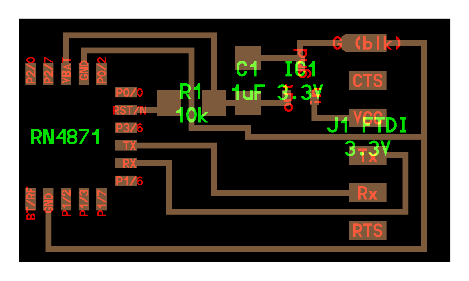
I chose to work with the RN4871 module for 2.4 GHz Bluetooth. It works well for short distances and doesn't require as much power or complexity as Wifi, which more than suits my purposes. In the interest of time, I'll be using Neil's hello.RN4871.ftdi board and my airplane PCB from week 9, and will design my own board for RN4871 another time. The pins don't line up exactly between these two boards, but I can just use some male-to-female connectors.
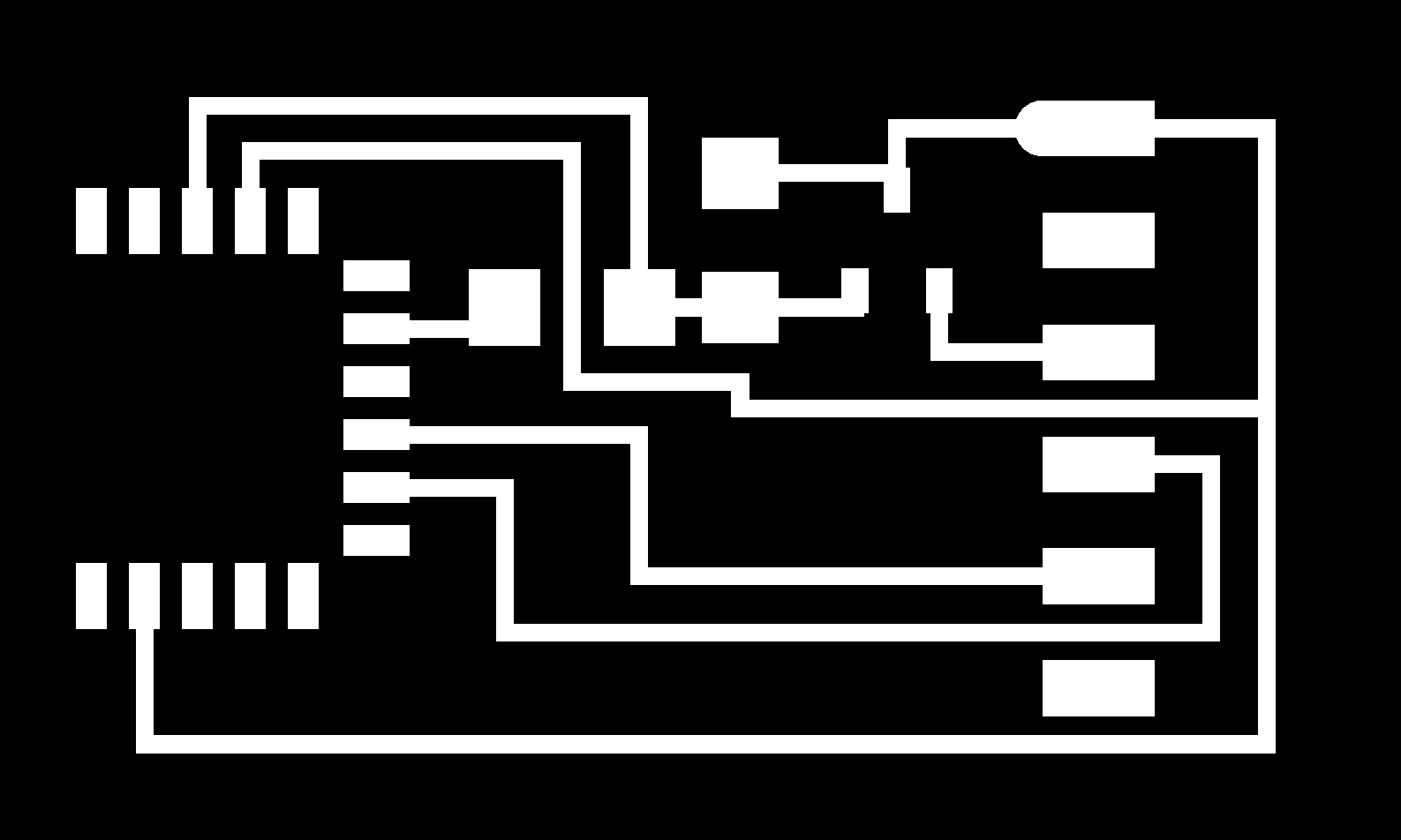
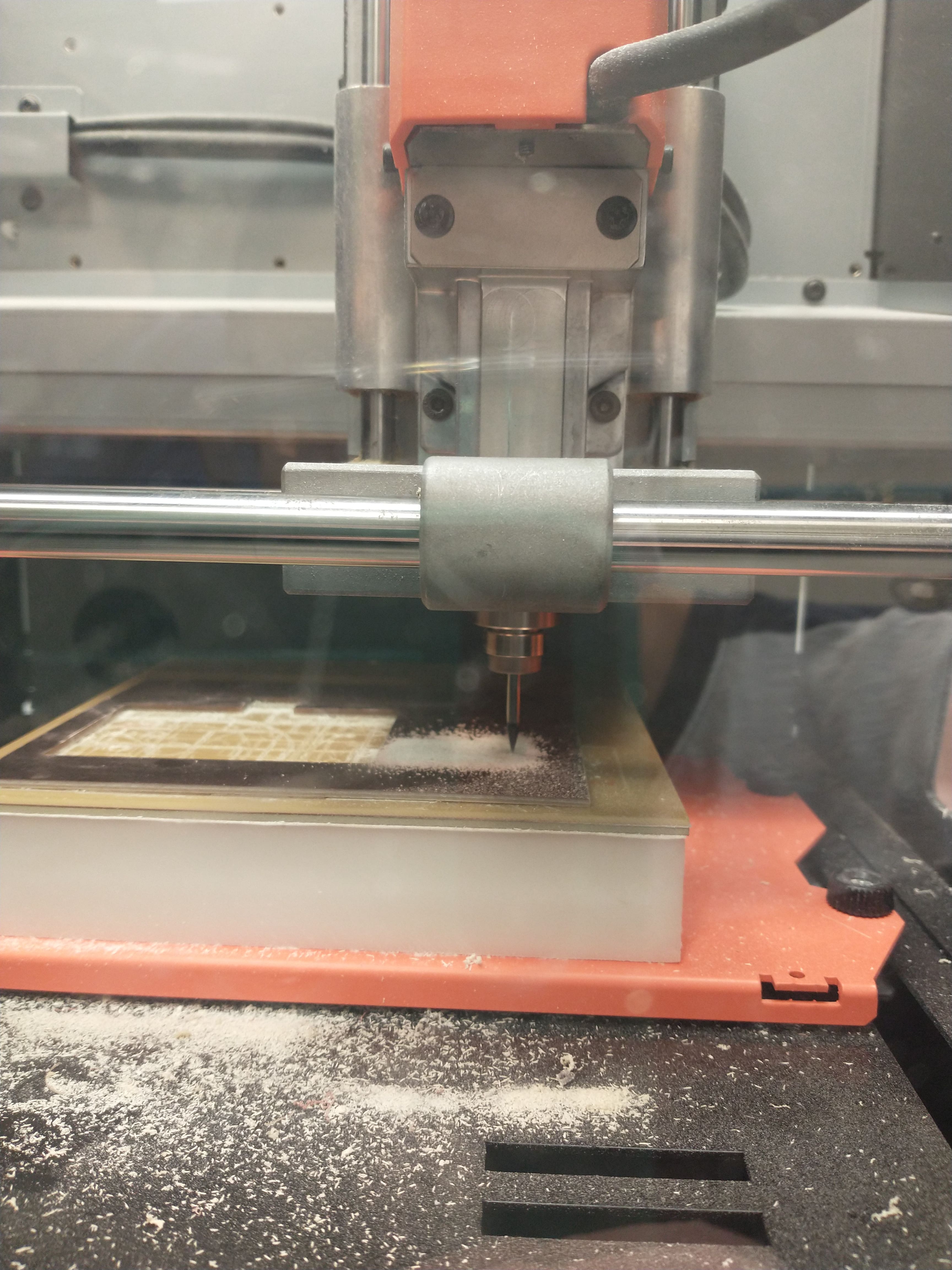
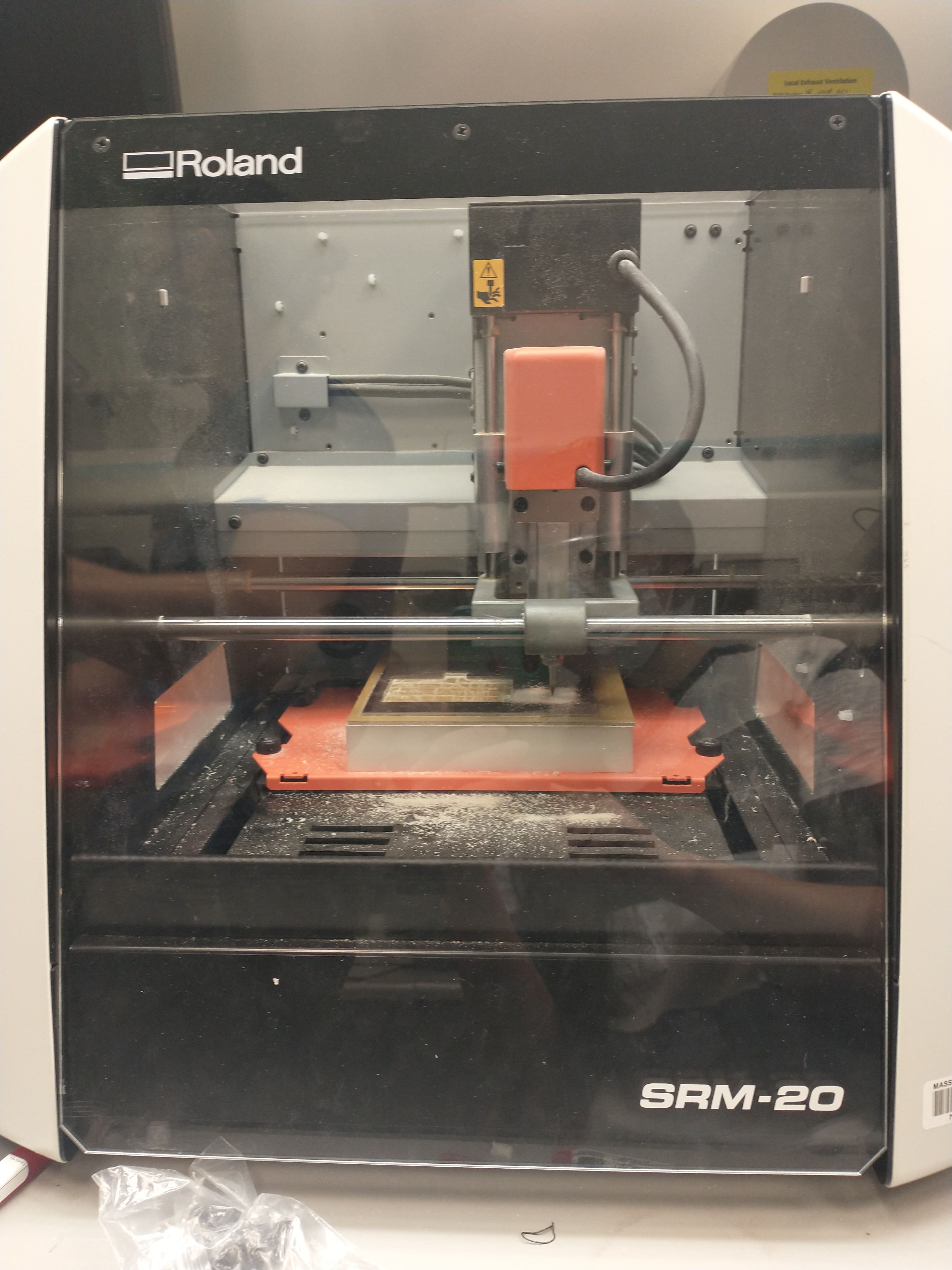
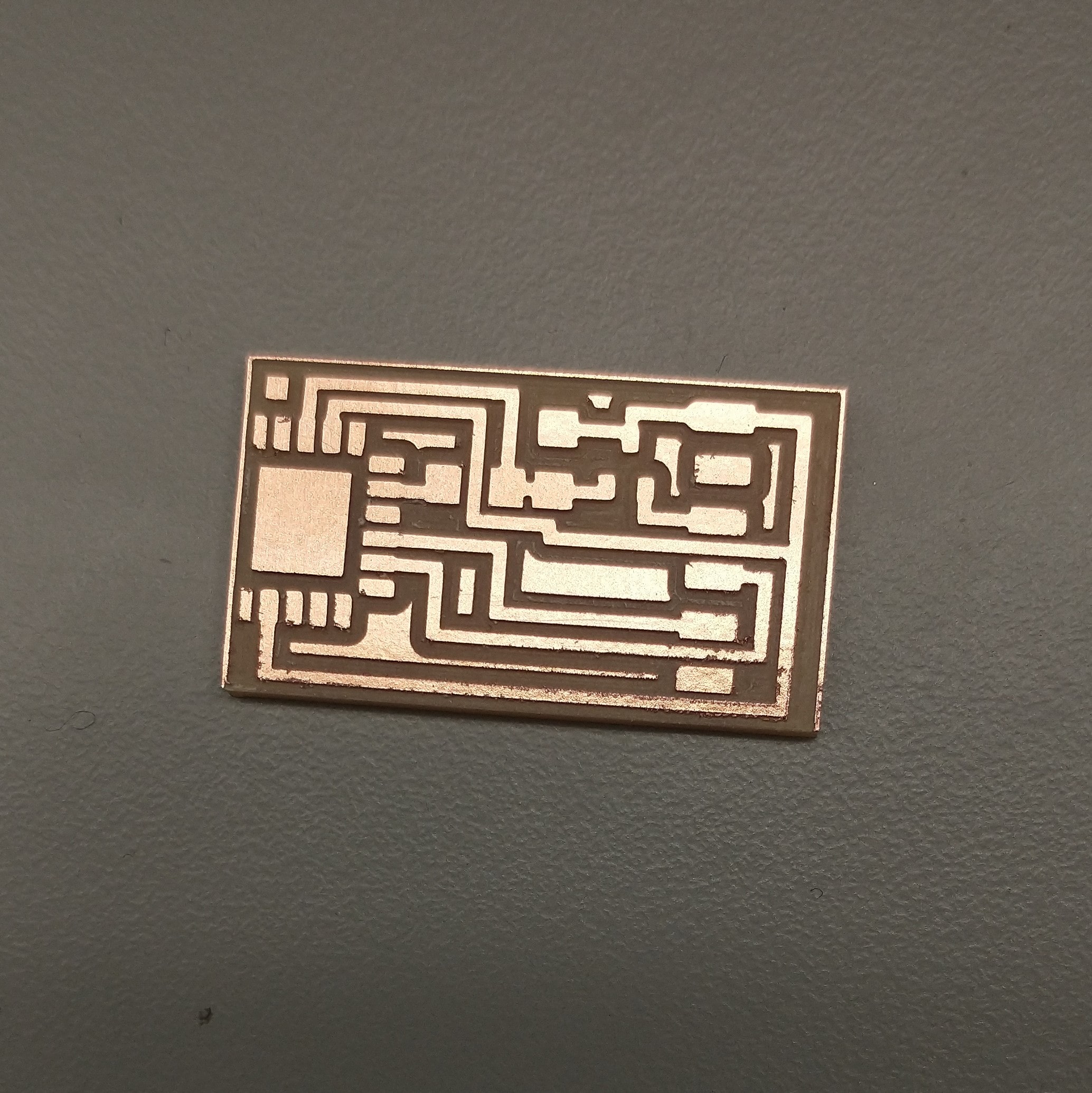
I used mods to turn the traces and outline PNG files into .gbr files, but the traces didn't load correctly in Bantam Tools for some reason (and would just show the outline, even when I only loaded the traces file). Setting mods to outline instead of fill caused (incorrect) traces to show up, and inverting the PNG didn't help. Despite our best debugging efforts, mods and Bantam Tools simply did not cooperate with this board (although they worked correctly with a different board), so I switched over to using the Roland mill.
How To Roland:
Parts
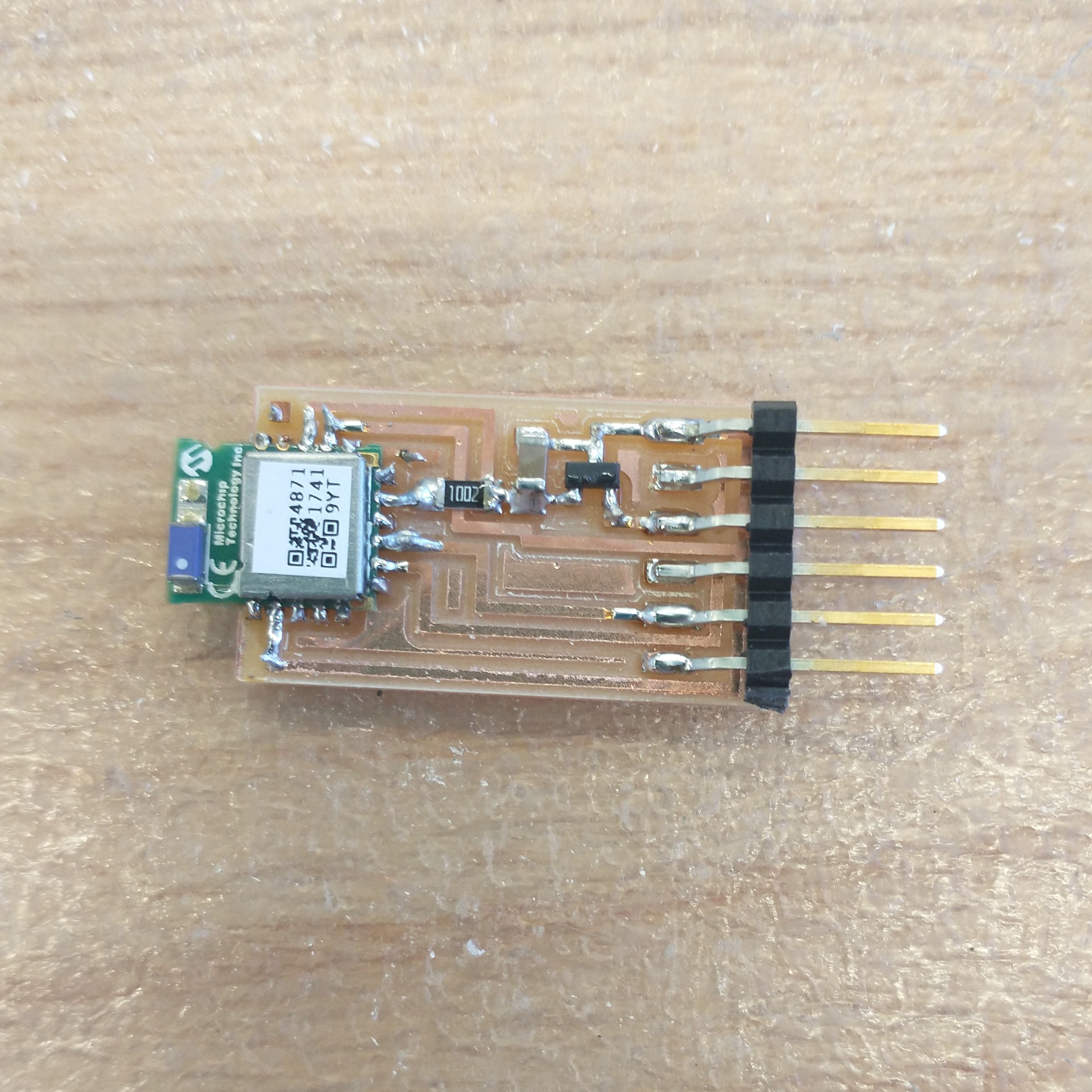

The pin connectors on this breakout board, from left to right if the RN4871 is pointed towards you, are GND, N/A, VCC, TX, RX, N/A.
As mentioned before, I had planned on connecting my plane PCB to this breakout board (pin order, from left to right: VCC, GND, TX, RX). However, the last piece of code uploaded onto the microcontroller was an attempt to control LEDs, and the Bluetooth module doesn't need to be connected to a microcontroller to function, so Anthony whipped out a cable that directly connected the board to my laptop's USB port.

To establish a Bluetooth connection between my phone and board, I referenced page 61 of the RN4871 user guide. Open up Serial Monitor in Arduino (the sketch file itself doesn't matter) and make sure baud rate is set to 115200. It turns out you have to use the "no line ending" setting for the first $$$ command and switch to "carriage return" for the other three commands. (I'd initially tried doing all 4 commands on each of the 4 communication options - by unplugging and replugging the USB every time I switched - and was confused as to why the serial monitor gave me zero feedback for the commands I sent, except for the $$$ command on no line ending.)
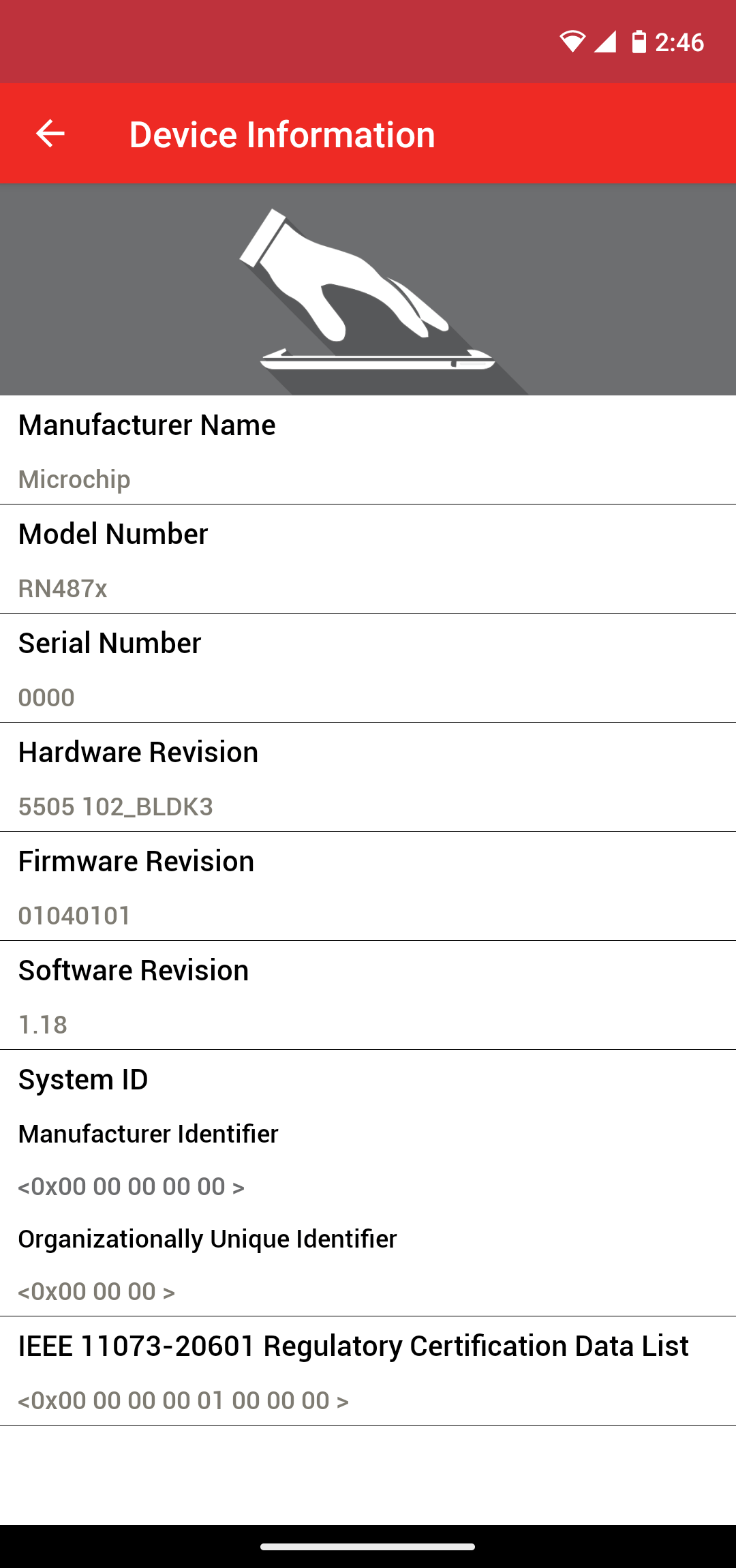
I couldn't find the Smart Discover app recommended in the user guide, so I installed the closest option instead - Microchip Technology's Microchip Bluetooth Data app - and managed to connect to my board!

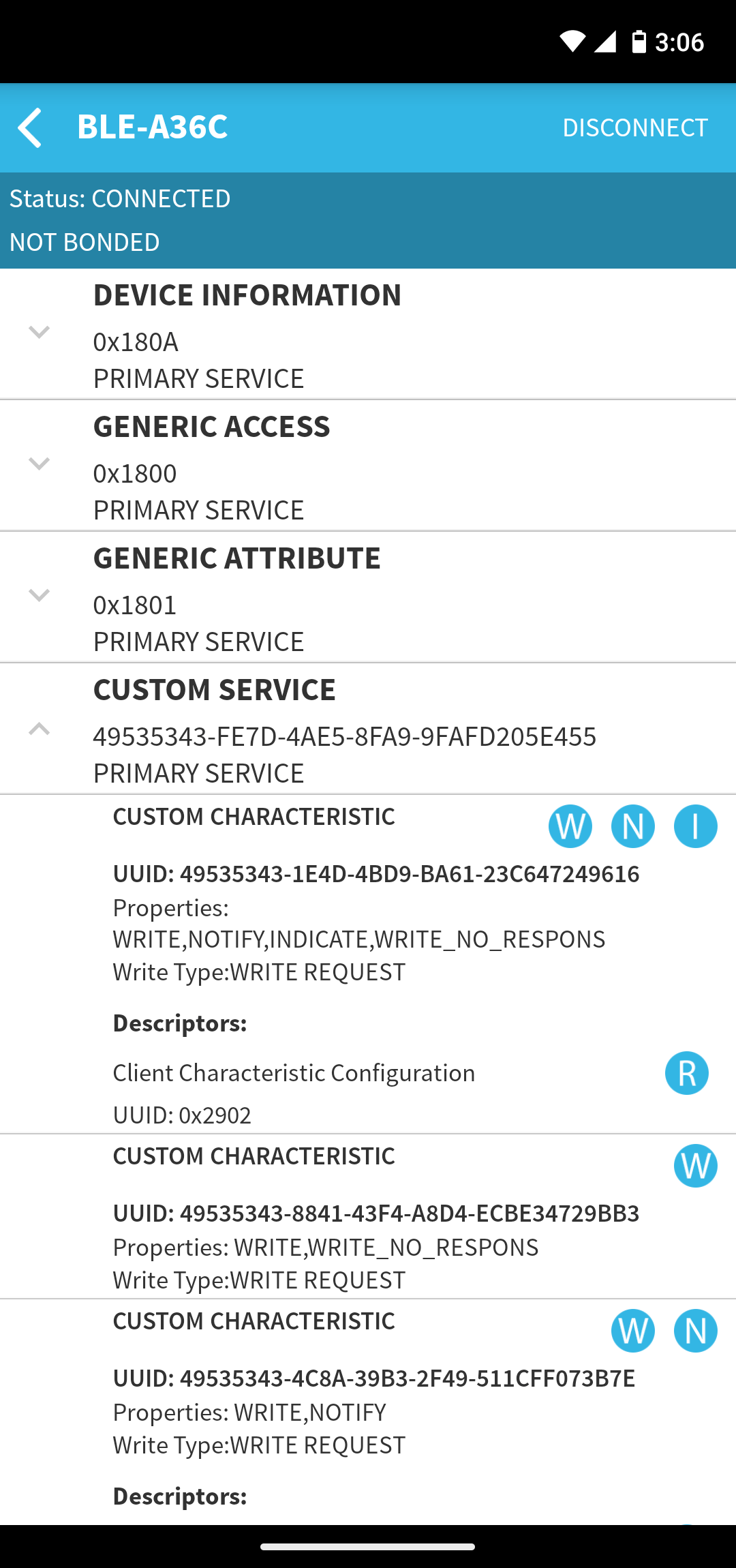
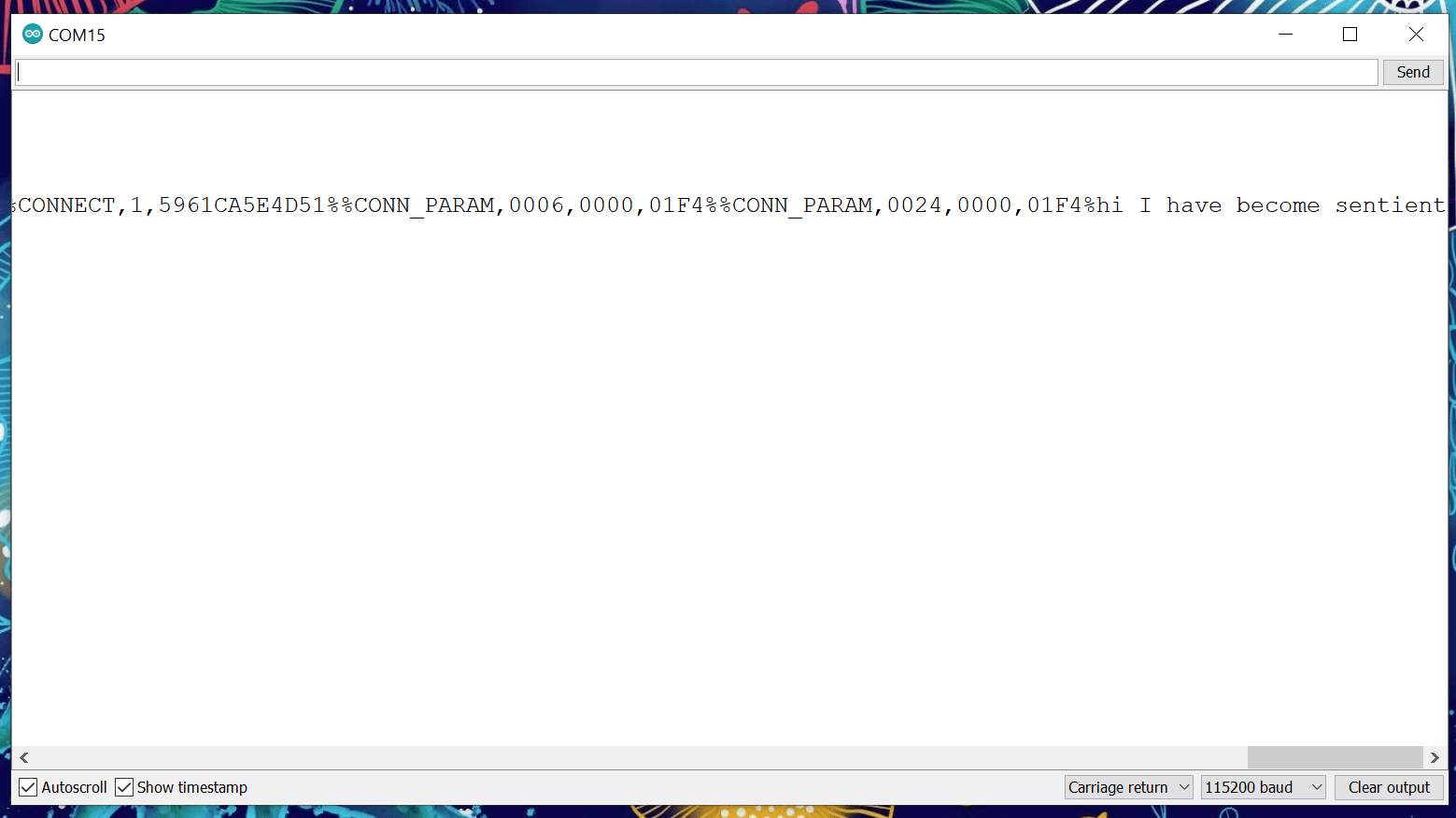
However, I was unable to send any information to the board with this app, so I instead installed Bluepixel Technologies' BLE Scanner. Clicking the W under "Custom Service" allows you to type a message to send to the connected device.
For future networking and communication work, I'd like to look into adding Bluetooth modules to the PCB that will control the LED on my final project and to the PCB that controls my OLED display, so that when a plane shows up on the runway, its corresponding info shows up on the OLED display.
Huge thanks to Anthony for all the recommendations and debugging assistance, as well as Alec and Carson for helping me work on the issue with Bantam Tools.