

Corel is the software where you can specify settings for your material when sending your design to Universal Control Panel - the software that actually controls the laser cutter, allows you to reposition the entire design, and check the location of your design. Corel takes images and even pdfs, but dxfs are optimal in case you want to make changes right before cutting. Set line widths as hairline and the colors as appropriate for your purposes. Both the laser cutter (power button on side) and the vent (via power strip switch) need to be on. Set the focus of the laser by manually moving the bed of the machine.
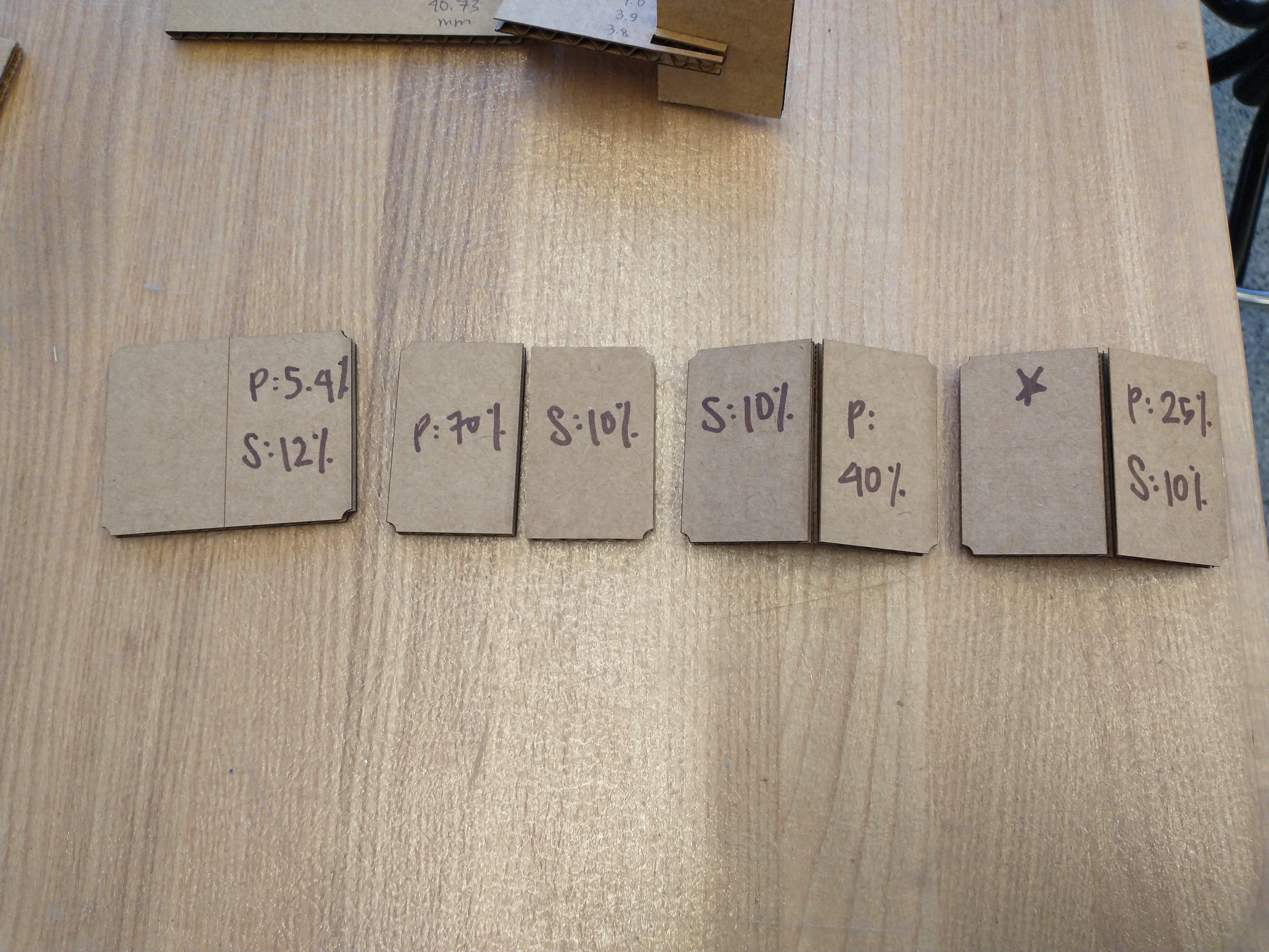
My section ran a few tests to determine the optimal settings for the cardboard we would use. For the larger Universal Laser Systems laser cutter, we began at
100% power and 20% speed and incrementally decreased the speed until the laser comfortably and consistently cut through the cardboard.
We chose to cut out squares to serve as kerf measurements and also tried rastering, the results of which are difficult to see on cardboard.
As our construction kits would involve cardboard pieces slotted together, we tried out a few different slot widths and found that the cardboard
fit well for slot widths of 4.0 mm to 4.2 mm, depending on how tightly you wanted the pieces to fit together. Finally, we tried to cut most
but not all of the way through the cardboard, in case any of us wanted foldable or curved parts.
Cut (Red): 100% Power, 10% Speed, 1000 PPI
Raster (Black): 26% Power, 100% Speed, 500 PPI
Engrave (Blue): 25% Power, 10% Speed, 500 PPI
Similarly, for the smaller laser cutter, 100% power and 18% speed were optimal for cutting.
Dimensions of three squares were measured to be:
20 mm Square: 19.75 mm by 19.68 mm
30 mm Square: 29.74 mm by 29.66 mm
40 mm Square: 39.72 mm by 39.75 mm
Listing kerf to be 0.155 or 0.15 mm seems to work.
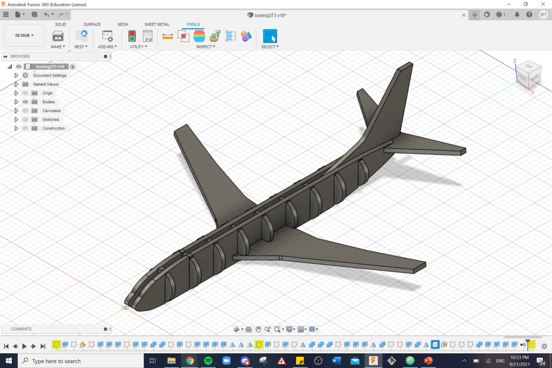
I took my CAD design of a Boeing 737 from Week 1 and turned it into a parametric construction kit, so that I could have my own Boeing 737 model in my room.
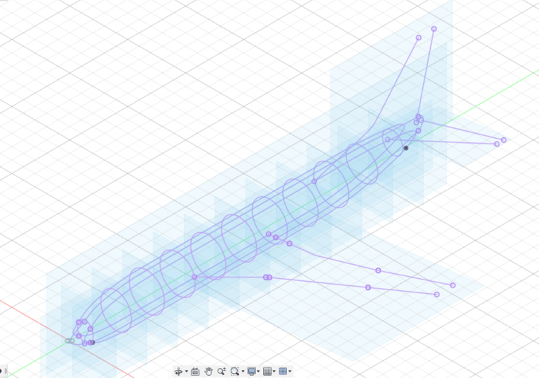
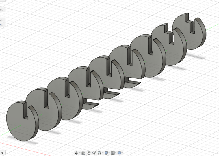
I created planes spaced evenly through the fuselage of the plane and used the Intersect function to obtain the outlines of the pieces that I wanted. Originally I wanted 24 cuts and chose to stick to 12 to avoid unnecessary overcomplication (and in retrospect, 24 cuts would probably have not looked as good).

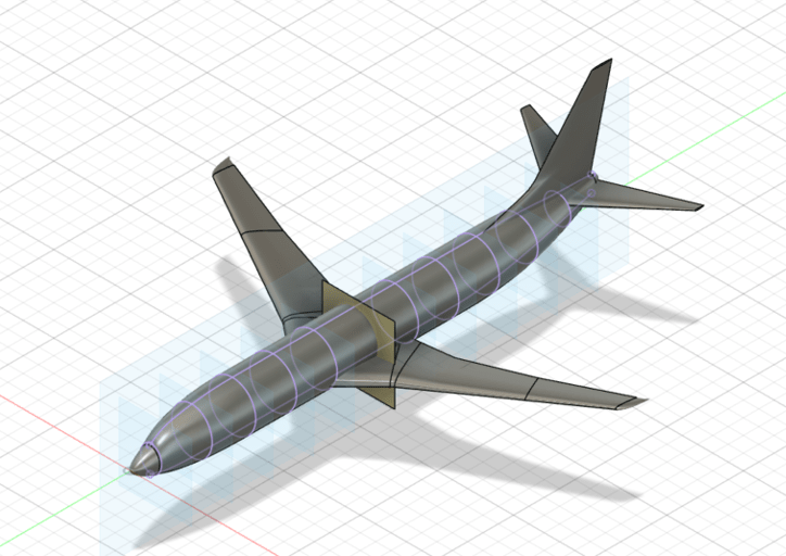
For the length-wise fuselage pieces, I considered having 1, 2, and 3 pieces. I wanted to illustrate the shape of nose and ensure that the model balanced easily, so I opted for two long fuselage pieces. (1 would probably have had balance issues, and 3 would have been complicated to implement, given how the remaining pieces would've fit in, particularly with the cardboard thickness.)
For the wings, I was originally hoping to showcase the decrease in airfoil size as distance from the fuselage increases. I thought of having a horizontal piece lined with multiple perpendicular airfoil pieces. However, the thickness of the cardboard is comparable to the thickness of the wing, so parallel airfoil pieces were not possible. Another option was stacking two pieces of cardboard (with a smaller piece sitting flush on top of a larger wing piece) to create the effect of wing thinning but the cardboard was still too thick for that idea.
Next came extruding the pieces to the thickness of the cardboard and interlocking each of the pieces - primarily by using Combine. For the round fuselage pieces, I ended up just propagating cuts across them all, to allow the length-wise fuselage pieces to slide in.
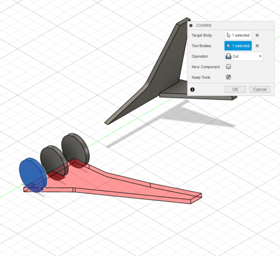
Instead of creating a new series of slits for the rudder as originally planned, after accounting for the thickness of the cardboard, I decided that the gap between the two long fuselage pieces would serve as a slit to hold the rudder in place. (This worked remarkably well in the final product.) Additionally, since some of my round fuselage pieces had to interlock with more than one piece, it turns out that a portion of the piece would end up disjoint for the rest. Hence why the belly of my airplane seems to have dieted and is missing its lower belly beneath the wings. I originally aimed for a 6-inch-long model and ended up scaling it up to 12 inches due to thickness of the cardboard.
Scaling down from the original CAD had no issues, but a parameter near the end of the design process of this laser-cut piece design ended up resulting in unexpected alterations. In particular, for my round fuselage pieces, the section that fit between the two length-wise fuselage pieces ended up shorter than anticipated. Additionally, my length-wise fuselage pieces somehow split into two, which I had to manually stitch together in Corel. Even with parametric design, setting the final dimensions at the start is a good idea, especially if I accidentally make alterations without accounting for potential future alterations.
The CAD file can be found here (which includes Week 1). Applicable parts are: fuse3-19, wing_left, rudder, stabilizer, realwingright, rightstabilizer, jank fused fuselage left, jank fused fuselage left (1), jank fused fuselage left (1) (1), and jank fused fuselage right. I clearly need to improve my naming schemes.
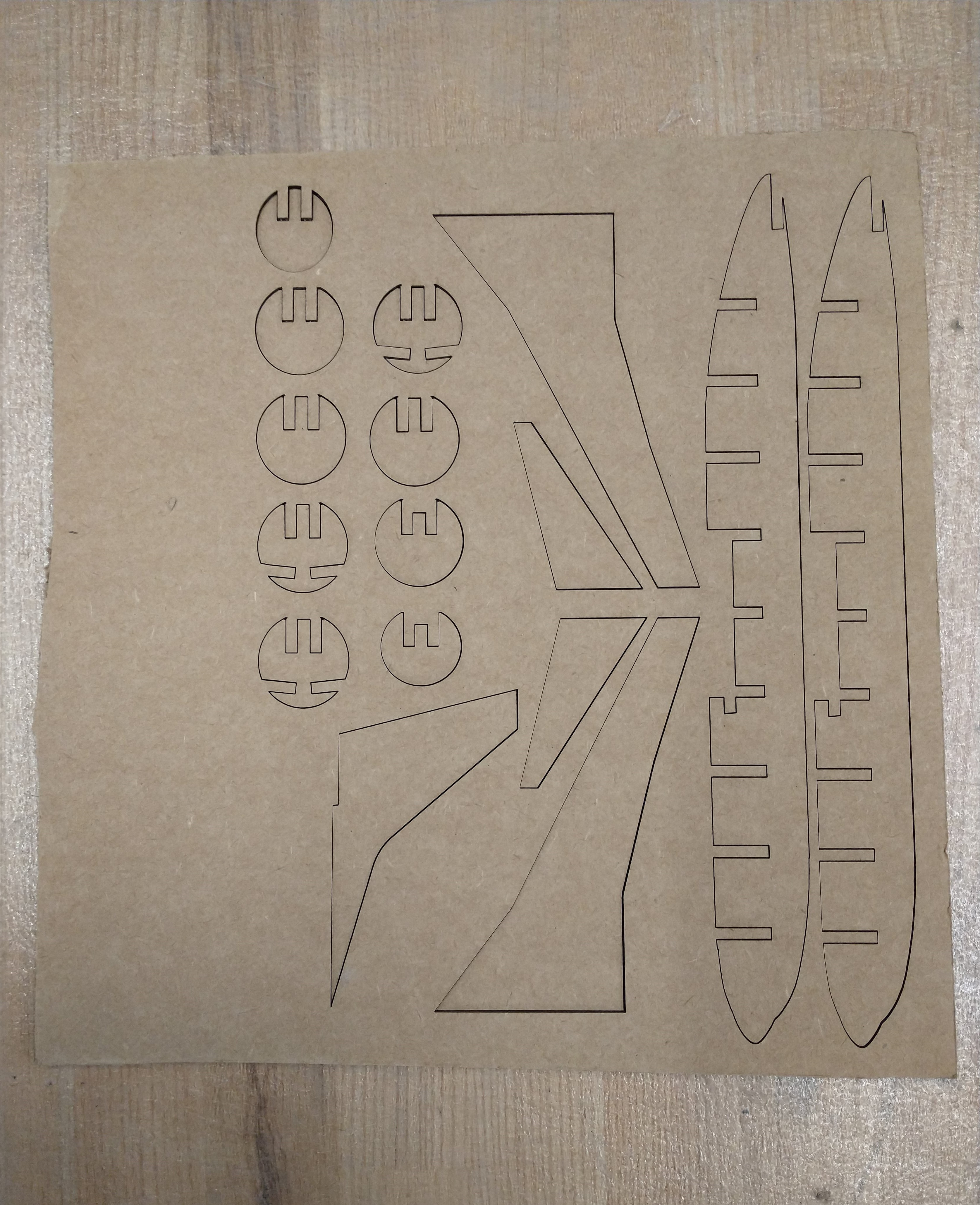
Ben found a handy Fusion plug-in that generates dxf files from the surfaces of bodies that automatically takes into account the kerf you enter. The plug-in creates on dxf file per part, so all parts must be manually lined up in Corel.
The laser cutting process went very smoothly. I test cut two fuselage pieces just to make sure the interlocking mechanism worked (which it did!) and then succesfully cut out the whole design on the first try.
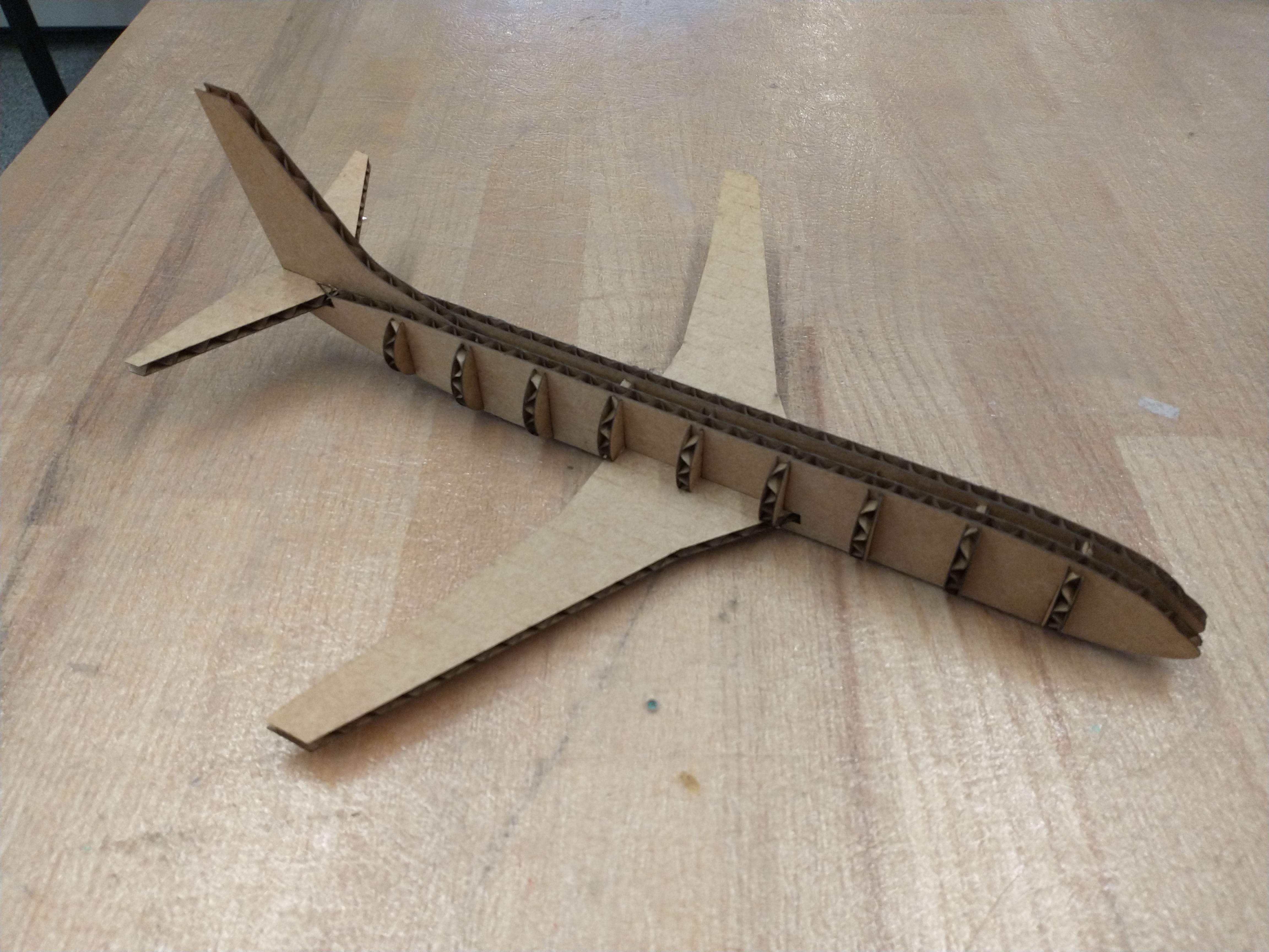
The 4.0 mm slot width that I use worked, though assembly required a bit more force than I would have preferred to insert some of the pieces into their slots. I would also have cut the stabilizer as one piece (and had a fold along the midline) as the primary force keeping the stabilizer on is the sandwiching of the rudder and the fuselage underneath, and thus the stabilizer pieces are prone to falling out. Hot gluing works fine instead.
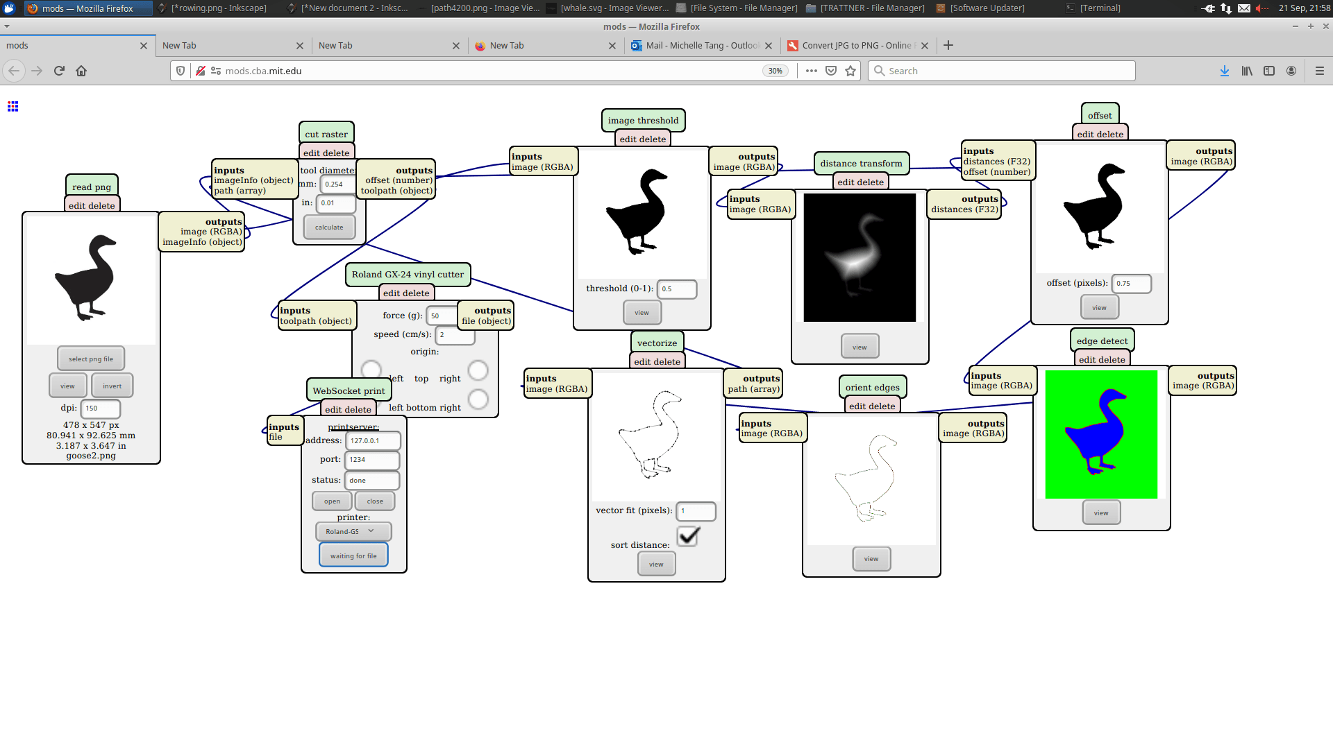
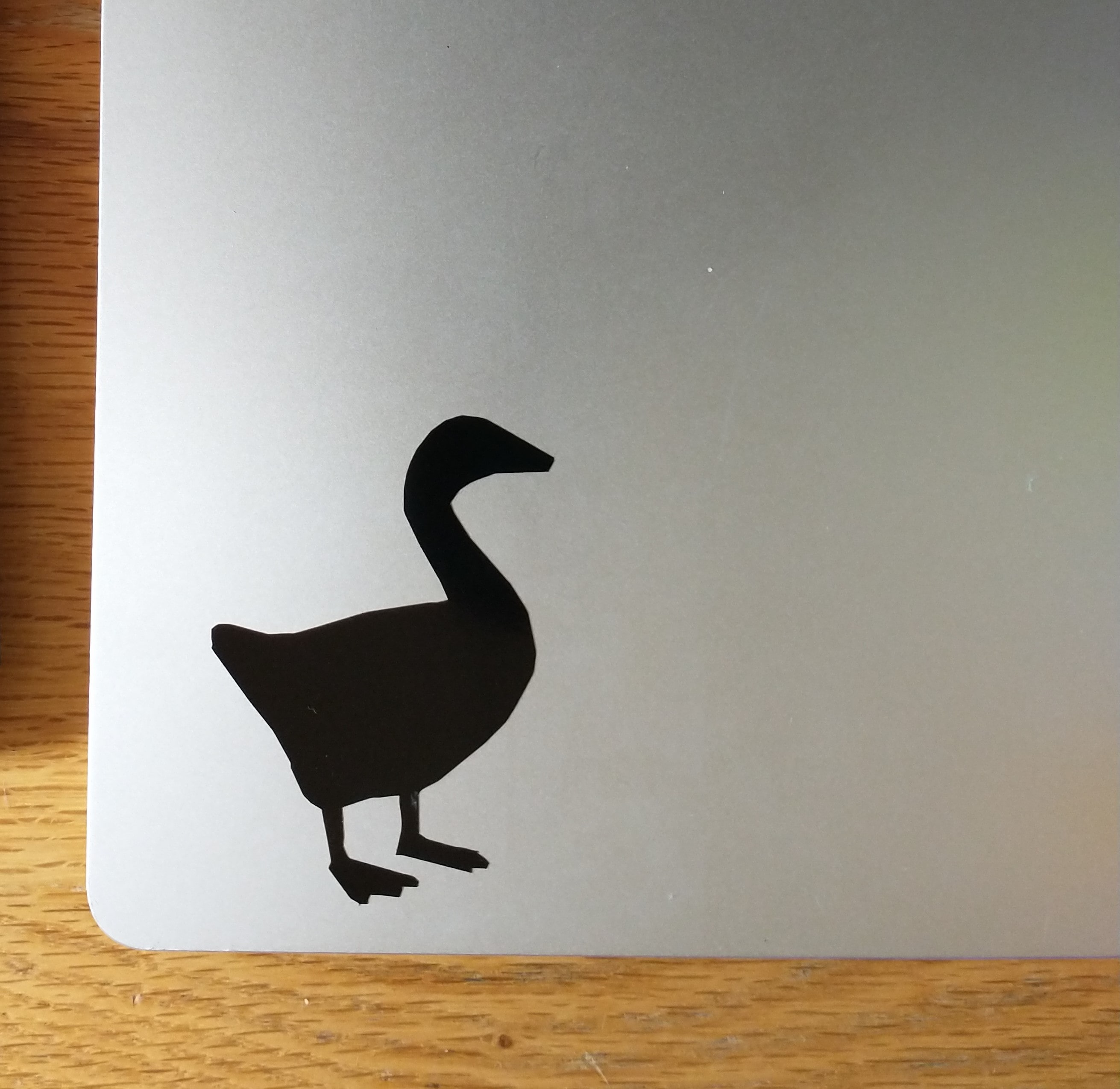
My alternate final project idea was a miniature or life-size version of the goose from Untitled Goose Game. In this video game, the player is a goose who runs around stealing from and generally terrorizing the residents of a small town. Although I ended up choosing the airport model, I still wanted a goose-related item and thus decided to make myself a goose laptop sticker. My best friend, when I told her about this project, also wanted a sticker, so I cut another goose (of a different design) for her as well (unpictured, as she has yet to receive it).
Changing DPI changes the size of the sticker, and mods uses image processing to create tool paths for the machine.
Much thanks to Anthony, Alfonso, and Ben for their assistance this week!