To determine the design rules for the 3D printers we had, we printed a number of test parts to characterize the Prusa and Sindoh 3D printers. STL files for these parts can be found under Design Rules under Printing.
Photos and a set of tables can be found here at Ben's site that summarizes our analyses of the prints conducted.
Since my final project will be a model of Boston Logan, I wanted to start working on some of the designs this week - specifically, the air traffic control tower. I did originally consider adding into my Boeing 737 design from Week 1, but the dihedral angles of the wings and stabilizer were 5 and 6 degrees respectively. From the design characterization tests that we performed for the Prusa and Sindoh 3D printers, these parts would have required support material, so I decided to go ahead and 3D print another object.
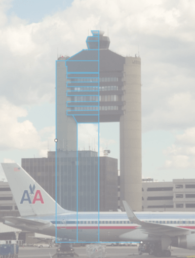
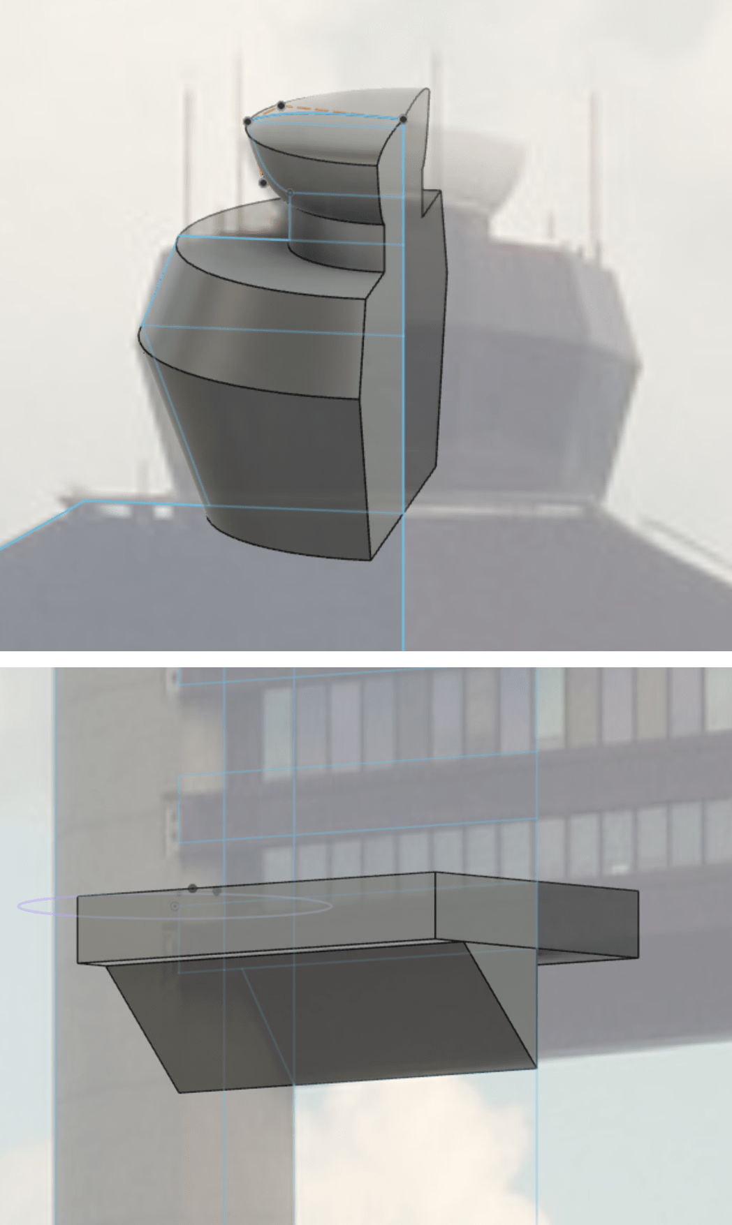
Boston Logan Airport's Air Traffic Control Tower, understandably, does not have blueprints available online, so I found the most front-facing photo I could find on Google Images (image creds: Brent Danley, Flickr), imported it into Fusion 360 as a canvas, and outlined the main features. Since the CAD model can be scaled up or down when 3D printed, I just set the height of my CAD to be 50 mm and measured out features (i.e. tower width of 20.181 mm, leg length) with the Measure tool. (The tower's original height is 285 ft tall (Emporis).) Since the tower is symmetrical, I only sketched out the left side of the tower. I ended up redoing the very top of the tower, using Control Point Spline, since I had originally outlined it using lines, when in fact that portion of the tower is curved. Given the size of the final 3D printed model though, this was just a minor change that didn't make a visible effect in the final product. I also am now naming all the pieces of my Fusion file!
Once the shape of the tower was outlined, I began extruding the shapes for the printers to create, using the width of the cylindrical legs (5 mm) to determine the width of the tower, since I didn't have the actual measurements.
Since the assignment is to create something that can't be manufactured subtractively, I wanted to add in floors inside the tower, so the floors and the windows would have to be created separately. Given the design characterization of the Prusa and the Sindoh, I made sure to make the window thickness at least 6 mm. The top row of windows was only 2 mm, but both printers should be capable of printing that gap.
After extruding the floors, I cast a sketch on the front plane on one of the floors, outlined the rectangles of the windows, and extruded the windows by the aforementioned thickness of 6 mm. The windows, however, do not extend all the way to the legs of the tower the way that the floors do. To fill in that gap, I sketched out, on one of the floors, the base of slanted window shape that I wanted, maintaining the 6 mm thickness, and extruded it to connect all of the windows into one piece. Once I had the windows for front of the building, I mirrored the shapes across the x-axis to form the windows on the back of the building.

I then had all of the 3D shapes ready, so all that remained was joining all of the shapes together and mirroring it across the z-axis to form a complete building. I was pretty happy with how it turned out, especially given that this was my first time CADing without referencing any resources or people. For future CAD efforts, I should probably save the CAD file more often at different stages of the process.

Once the CAD was complete, I exported it as an STL file to be turned into gcode for the 3D printer.
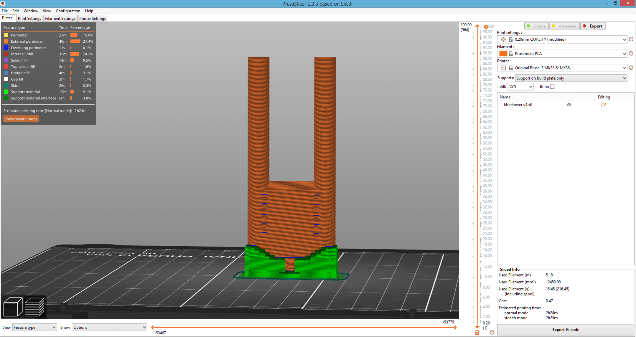
The PrusaSlicer software generates gcode - the file that we give to the 3D printer - for the Prusa. After importing the STL file, you can use the toolbar on the left to work with your parts. The Lay Flat tool, for example, allows you to select a face of the part to place on the bed. Cutting turns your part into two that move independently of each other, allowing you to rearrange them.
The print settings have multiple menus where you can add features for strengths, layer height, and infill percentages. The overhang threshold is the angle at which support is turned on. Skirts and brims adds extra material around your parts, if you have issues with part adhesion to the bed of the printer, which is generally specific to part geometry. (Ex: warping up from the bed, especially for ABS material, which was originally an injection molding material.) Skirts go around the part, and brims attach to the part. Rafts add a layer on the bottom. Support settings have to be manually turned on. Painting on supports is also an option for you to indicate where you want to have supports (in blue) and where you don't (in red).
Once your settings are as desired, hit the Slice button to view your part. The slider on the right allows you to view how each layer is built up. Hit "Export to G-code" to save the file. The Prusa requires an SD card for file transfer and automatically sorts the files by date modified. The Prusa homes itself by looking for magnets underneath the bed and for any bed deformation. It also automatically prints a stripe of material to clean the nozzle.
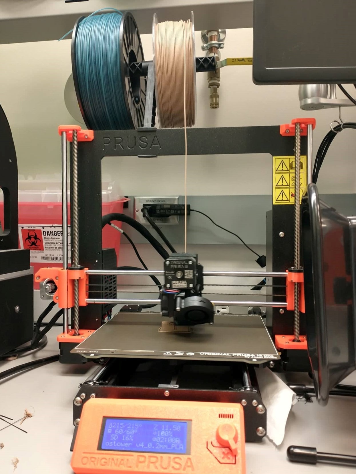
Anthony had a lovely filament for the Prusa that was PLA with sawdust mixed in, and he told me that scaling up my model to 100 mm in height would still be an acceptable print time. To minimize the amount of supports necessary (thank you, ATC tower, for having such long legs), I considered printing it face down. However, the rounded top of the tower is wider than the rest of the building, so we decided to print the building vertically upside down, which at least meant that the legs would print much nicer than it would have been if printed face down. The final print time came out to be about 2.5 hours.
The first print ended up detaching from the bed of the machine, so I added a skirt and slowed the printer's perimeter speed from 45 mm/s down to 30 mm/s. These new settings worked well, and the first failed print served as practice for removing supports and sanding. In the very last minute of the second print, the legs of the structure encountered an issue, since the longer lever arm distance of the legs meant that the print would wobble, so the printer head got caught on one of the legs.
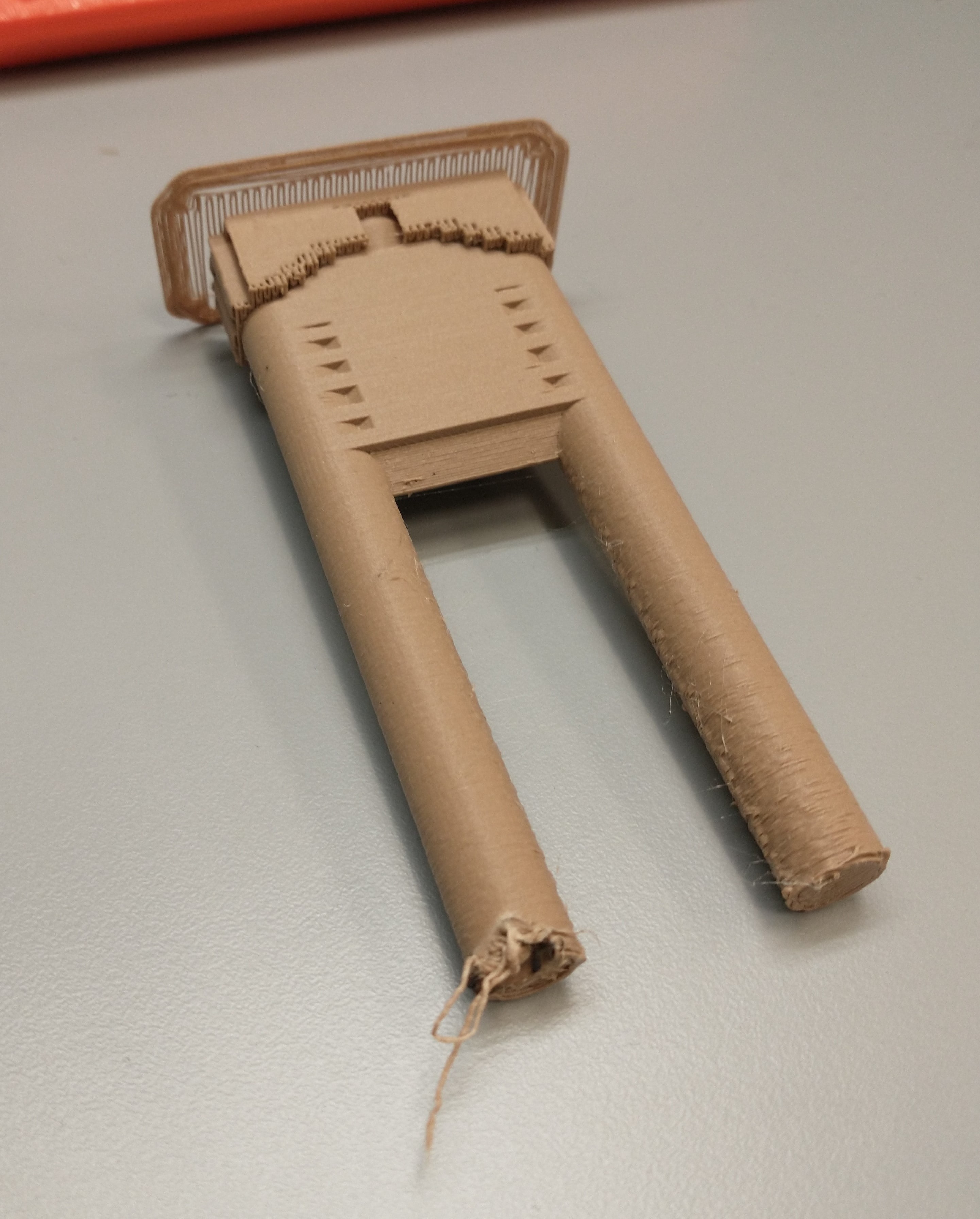
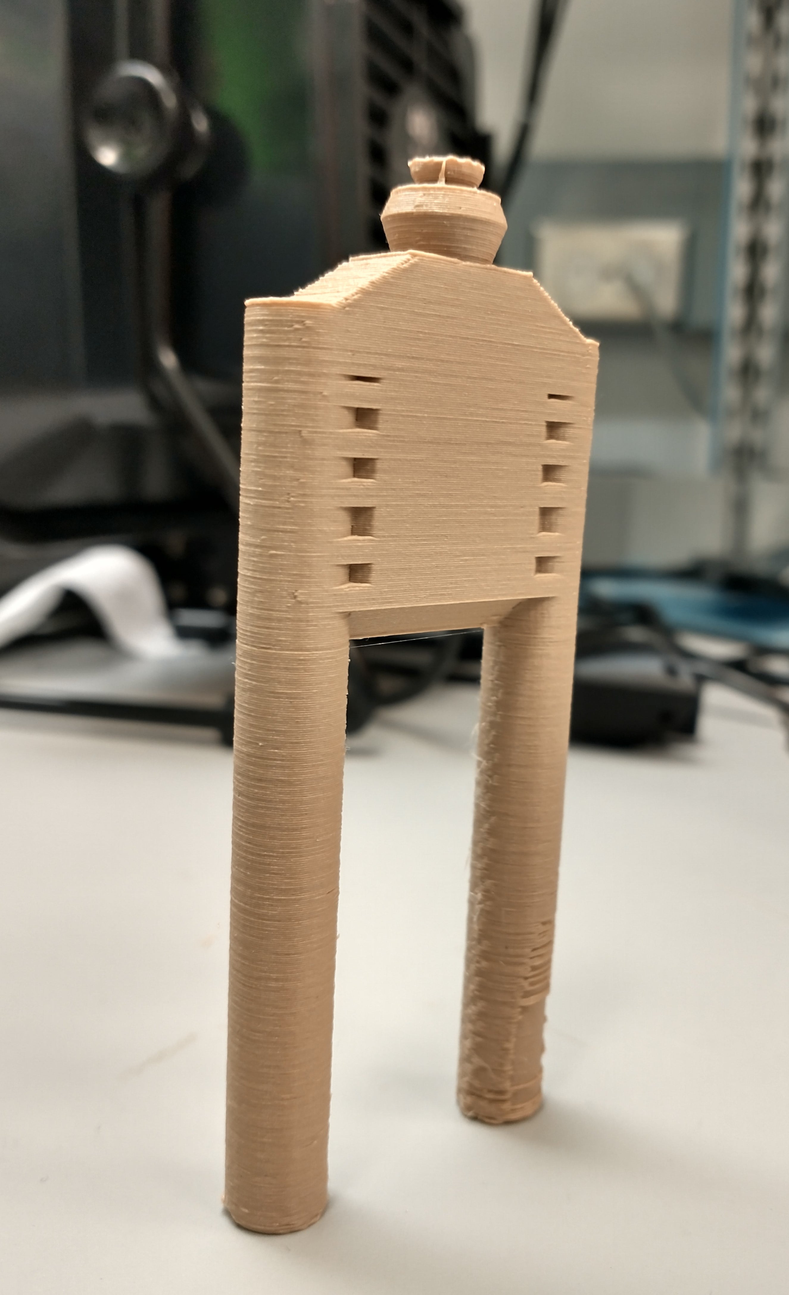
After removing the supports and clipping off excess material, the tower turned out pretty well and even stands up on its own. I decided not to sand it down, due to the resulting change in color. Here's the final result!
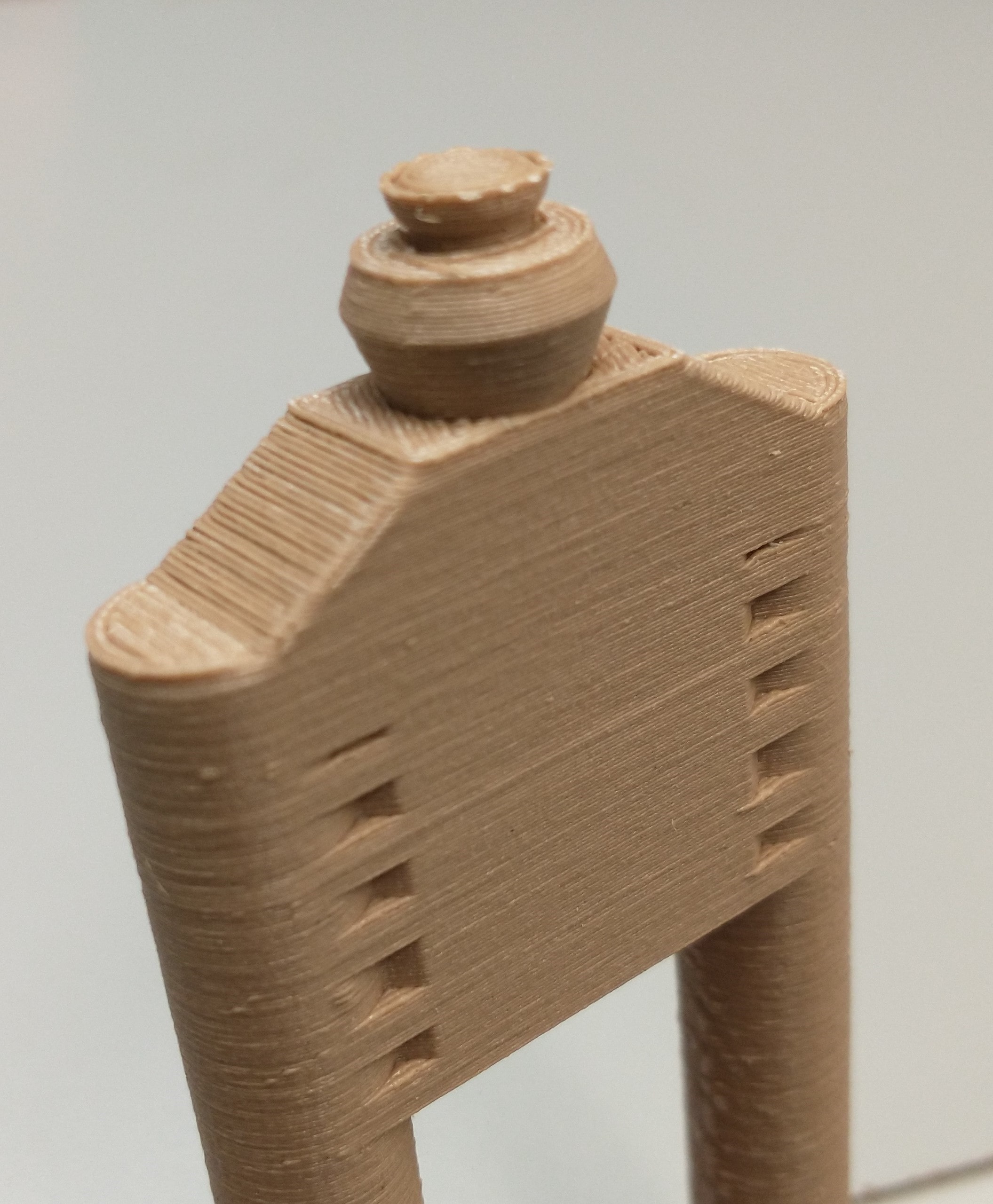
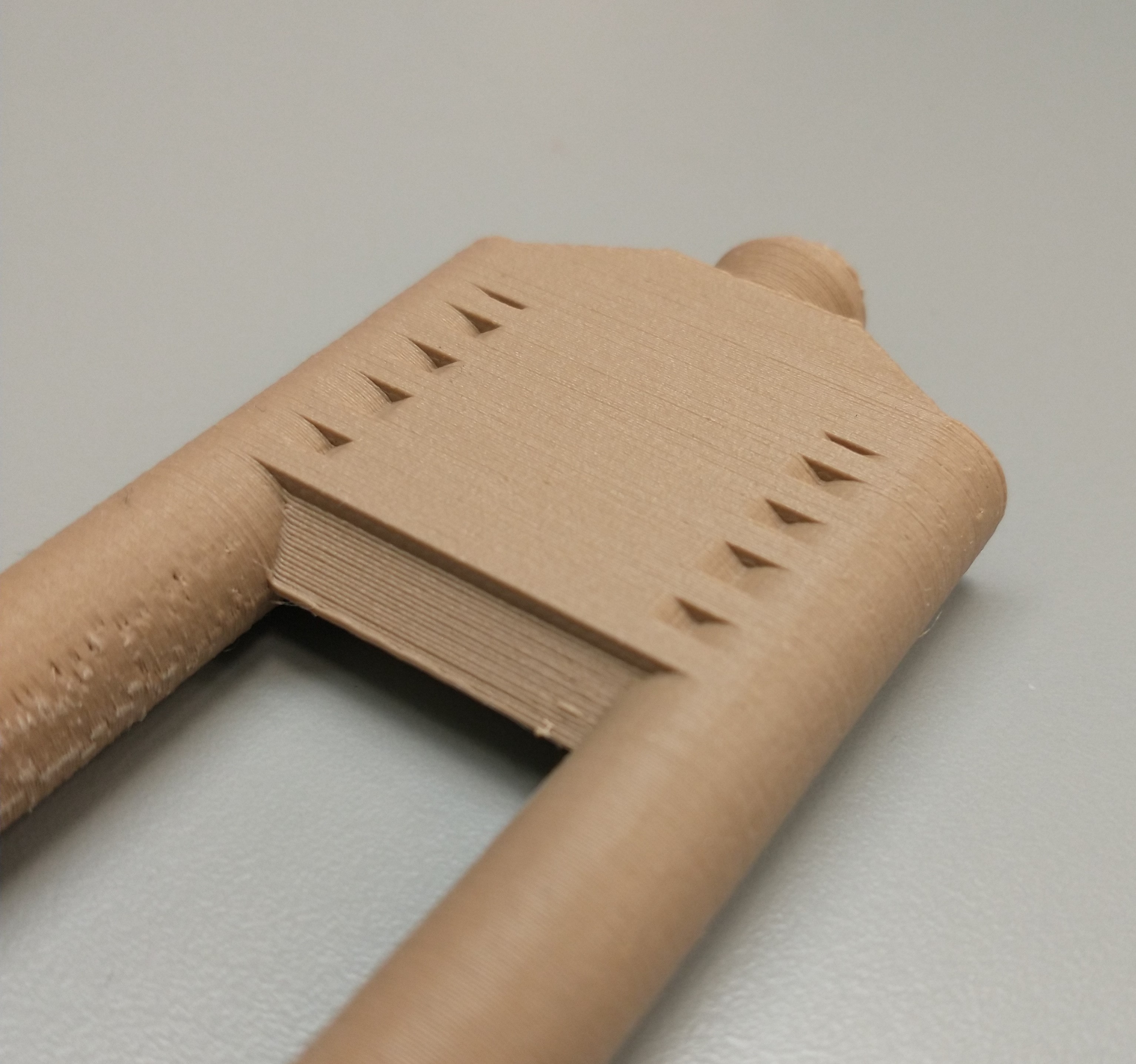
Some close-up photos! The window gaps came out rather nicely, and if I wanted to use this print for my final project, the other airport buildings would surround the legs of the tower anyway.

The CAD file can be found here
We used the 3D Sense scanner and software in the EECS lab to try out 3D scanning. In general, clear, dark, velvety, and/or non-reflective objects don't get picked up well by the scanner. The software displays features it's found in green and, once you're done scanning, allows you to crop and trim the model. You can then hit Solidify, Finish, and Export to print the scan with a 3D printer.
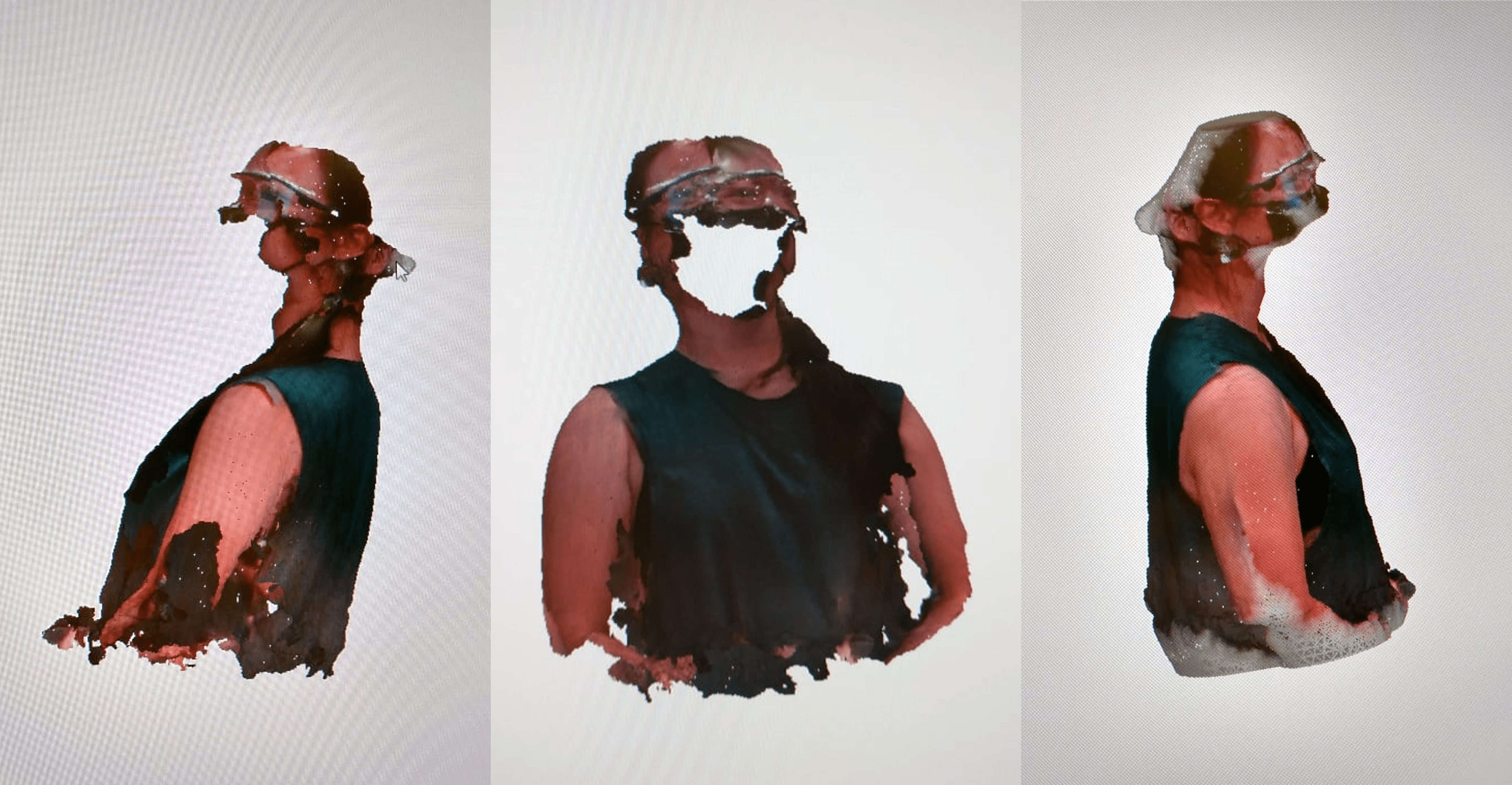
Instead of moving the handheld scanner around the object, Ben and I had the brilliant idea of keeping the scanner stationary and rotating the object - in this case, the object was me, and I think the scan looks just like me!
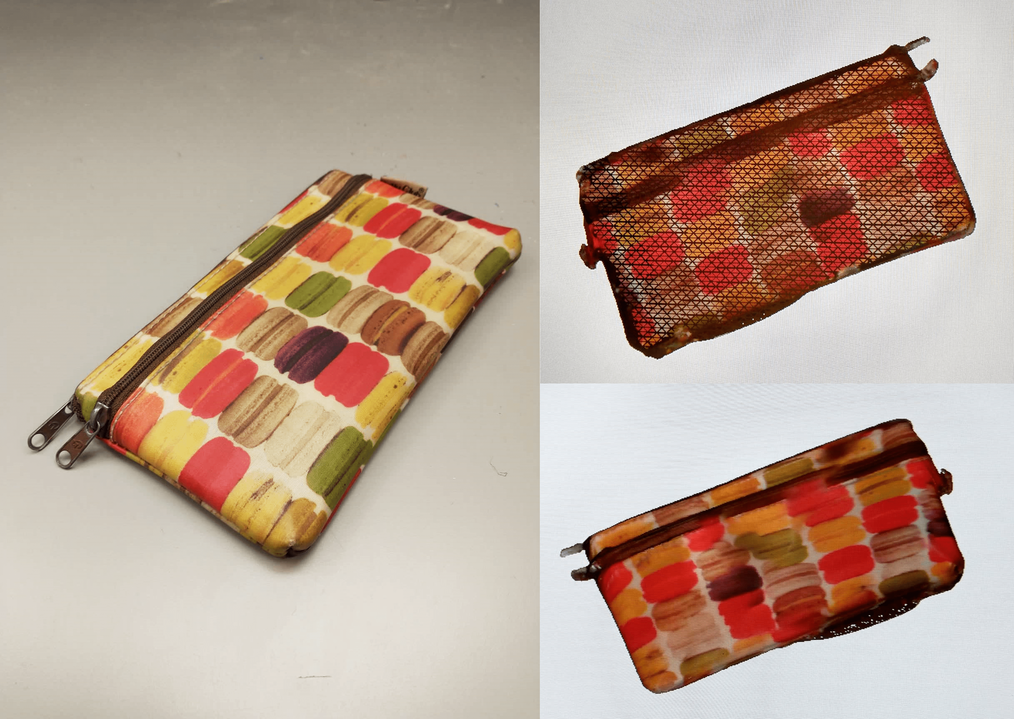
I also (properly) scanned my pencil bag for good measure.
Thanks to Anthony and Ben for their advice and assistance this week and to the entire EECS section for collaborating to print the design characterization pieces.