I thought up a few ideas that could be relevant to my final project:
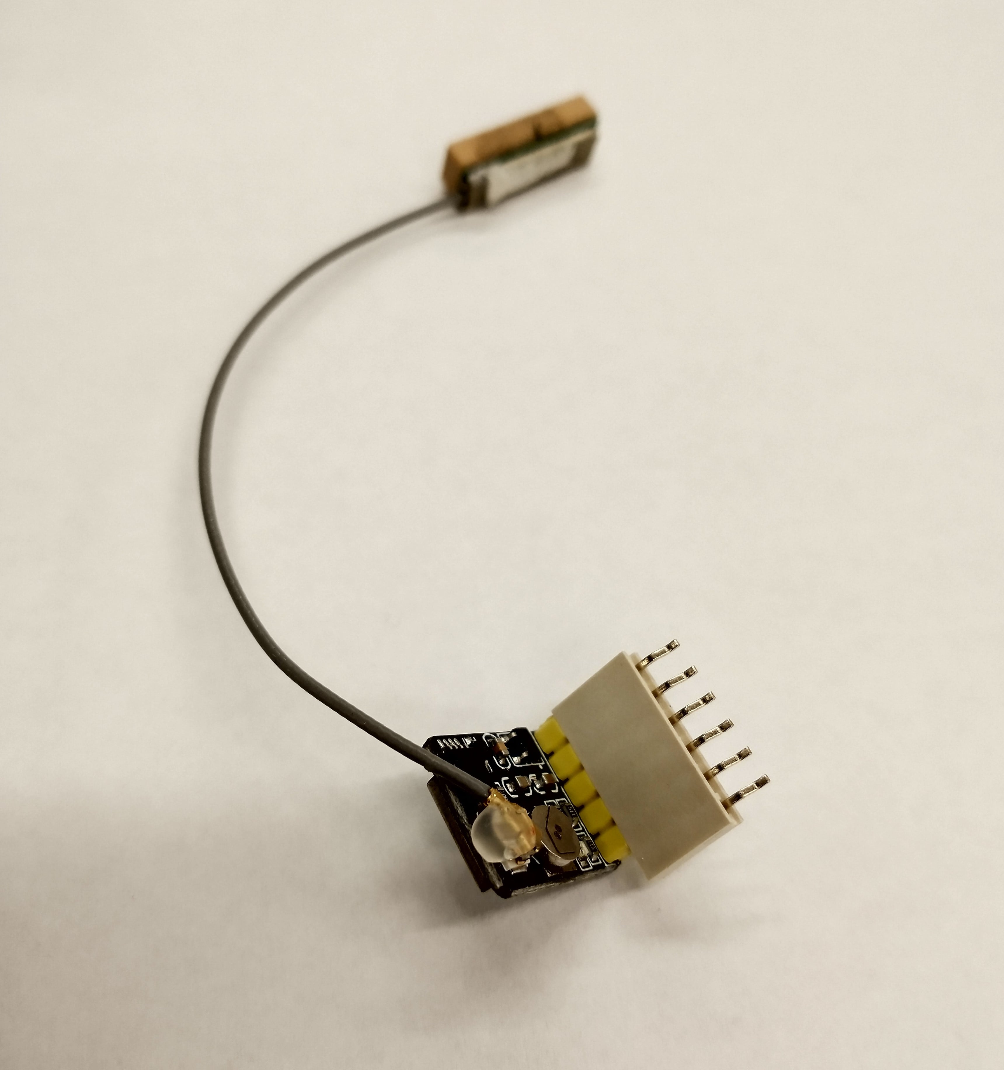
Because the GPS modules connects via TX and RX, I could just modify my schematic from Week 5 instead of starting entirely from scratch. I deleted the LED, button, and their associated resistors. The 2x5 connector is to bootload the board, and the 1x6 connector will be used to talk to another board - in this case, our GPS board, whose pins are the same dimensions apart as the 1x6's (thanks to Harrison for measuring for me).
To get the GPS board to plug directly into my new board, I had to reorder my 1x6 connector pins to match the order of the GPS board's (which were fortunately labeled on the back). They are as follows:

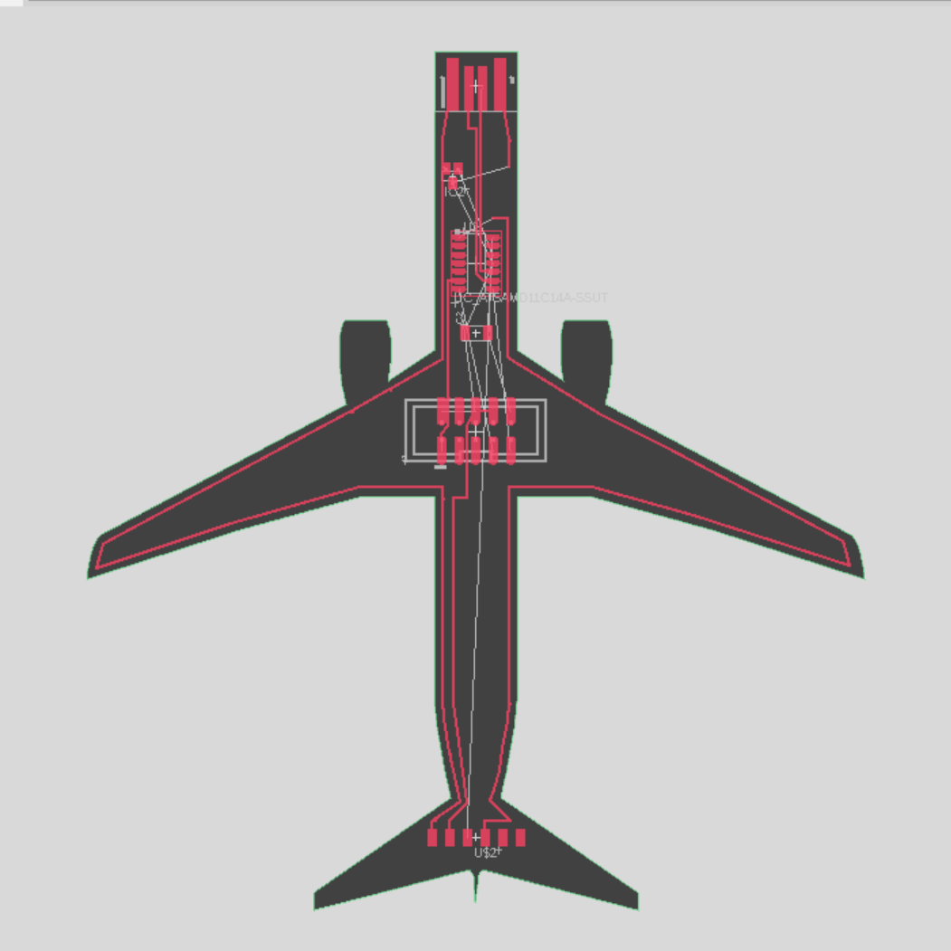
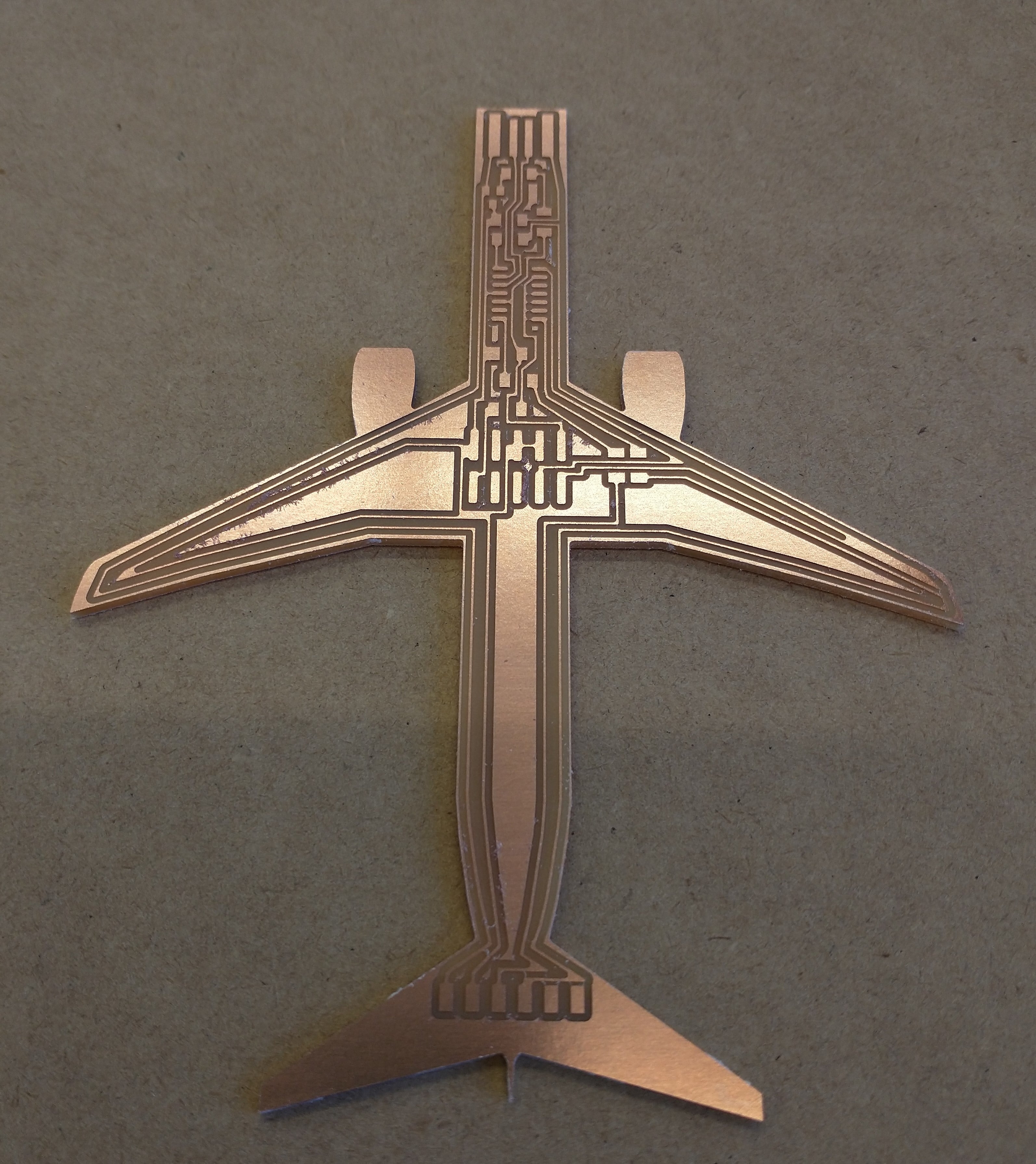
Since I kept my Week 5 board rectangular, I thought I'd have a bit of fun with this week's board and make it into a plane. I drew out an outline in Fusion, at first using Control Point Spline, but Eagle doesn't like that, so I redrew the curves with lines. I could've just sliced my CAD model from Week 1, but I wanted to add engine outlines as well.
There's a script that will import a dxf as an outline. Under Automation under the Manufacturing tab, run ULP, and there's an import-dxf ULP. Set the target layer as "20 Dimension" (to indicate it's an outline) and set units as mm. Then run the script.
Because I wanted to make the USB port the nose of the plane, I had to do some fiddling to ensure that the width of the plane fuselage is 12 mm, exactly the same as the width of the USB port. Unfortunately, there was something strange going on with the dimensions of the imported outline dxf. I used the Dimension tool to measure the width of the imported outline, deleted the outline, then scaled up my outline back to Fusion by the needed factor of 15, and reimported a new dxf. And that did the trick!
Now that I had my lovely outline, I started on the task of fitting all my parts onto the board - a tricky endeavor given that the fuselage is not very wide. Fortunately, I remembered to set my trace settings before I began routing. This can be done through DRC Check under the Rules DRC/ERC tab. Trace width is set under Sizes, and the rest is the same as Week 5.
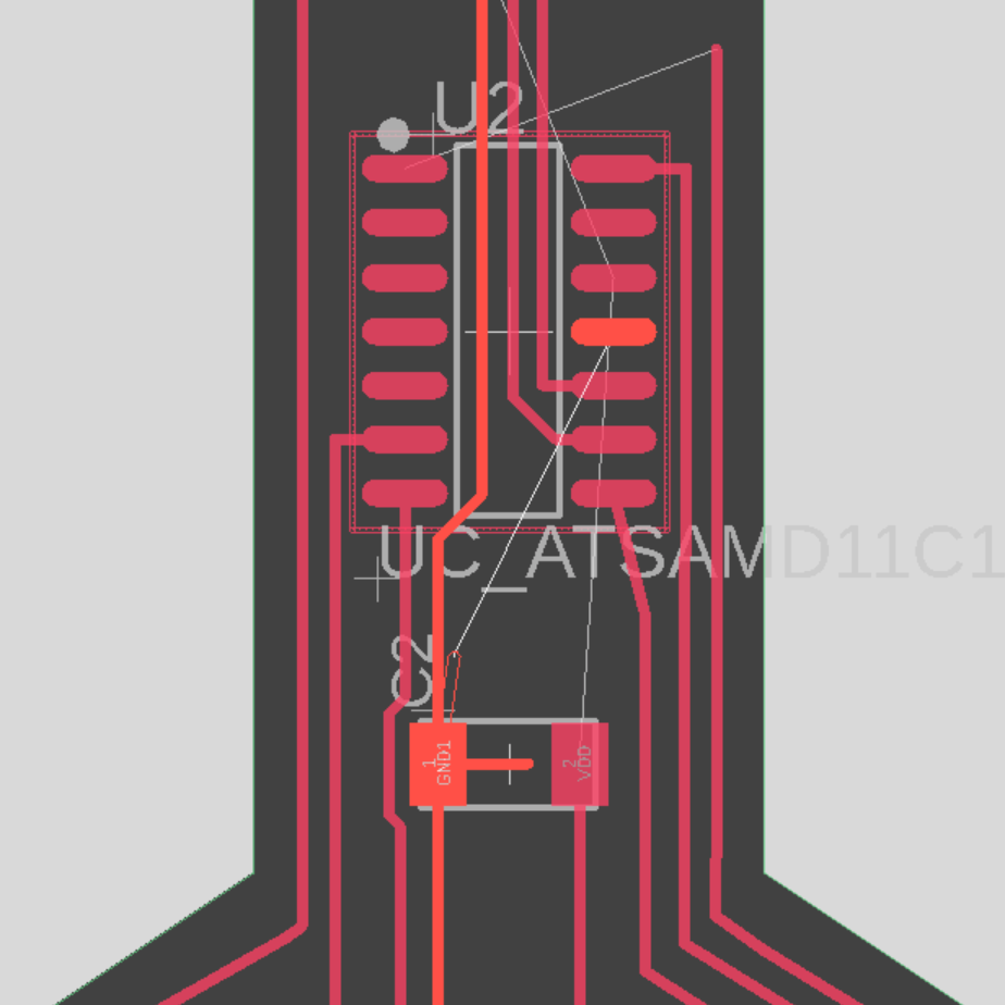
At this point, the friends watching me work were very amused at the sheer number of "ding" sounds that Eagle would give me every few seconds as I attempted to move parts and traces around. While watching me struggle to connect all the microcontroller pins, another friend commented on the usefulness of two-sided boards.
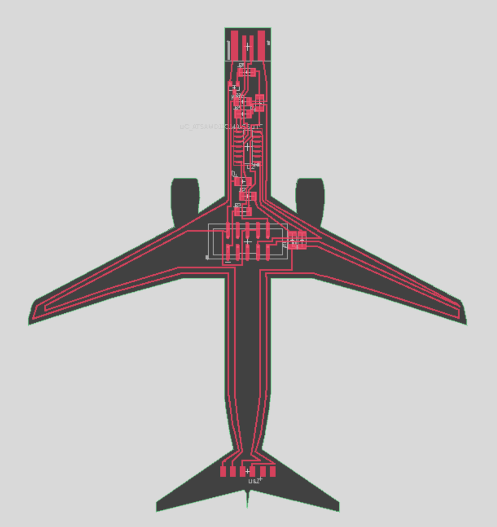
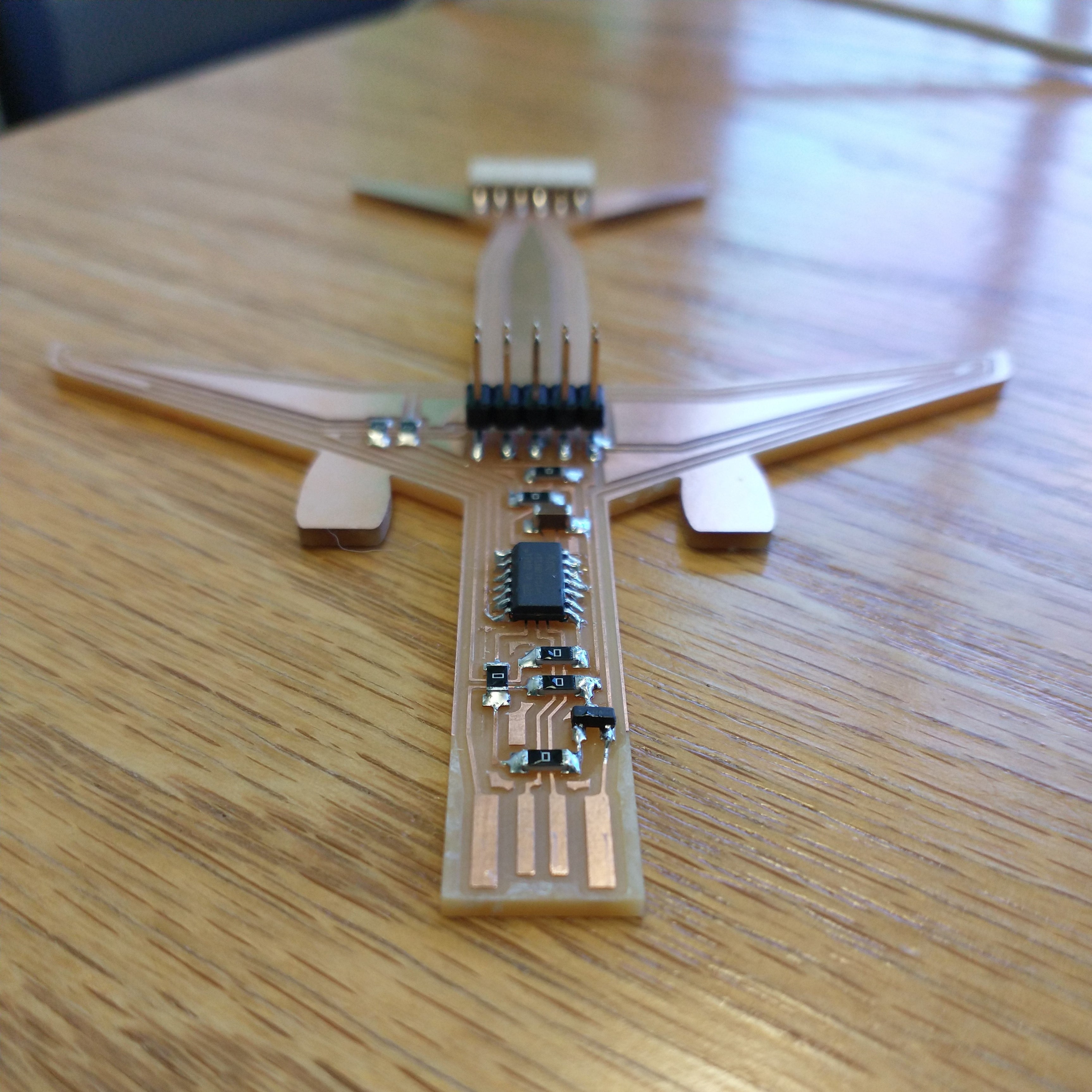
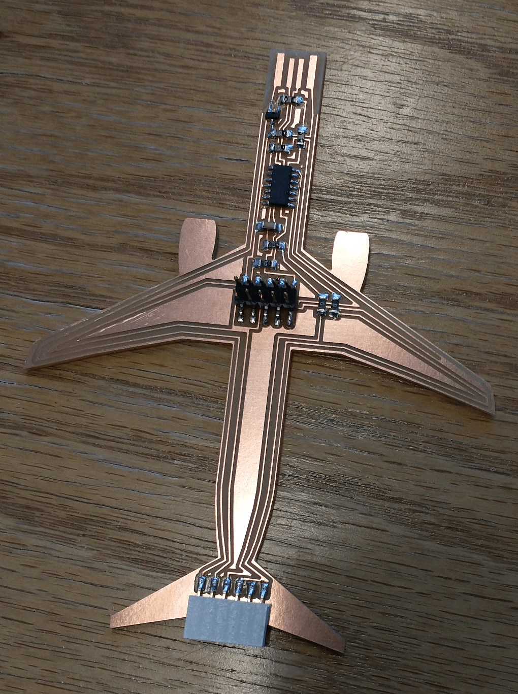
I managed to finish routing the board! Turning the microcontroller upside-down was an excellent choice and allowed me to fit more than 3 traces under the microconroller. I also ended up using 8 jumper resistors. Anthony also spotted a potential short, so I'm glad I asked him to take a look before milling.

The Eagle files can be found here.
Importing my design into Bantam Mills showed that my plane was too wide, so I shortened the wings a bit so that the entire design could fit on the material.

Luckily, my plane fits length-wise onto the material, albeit just barely. I'm really cutting this PCB so close to the edges of the board.
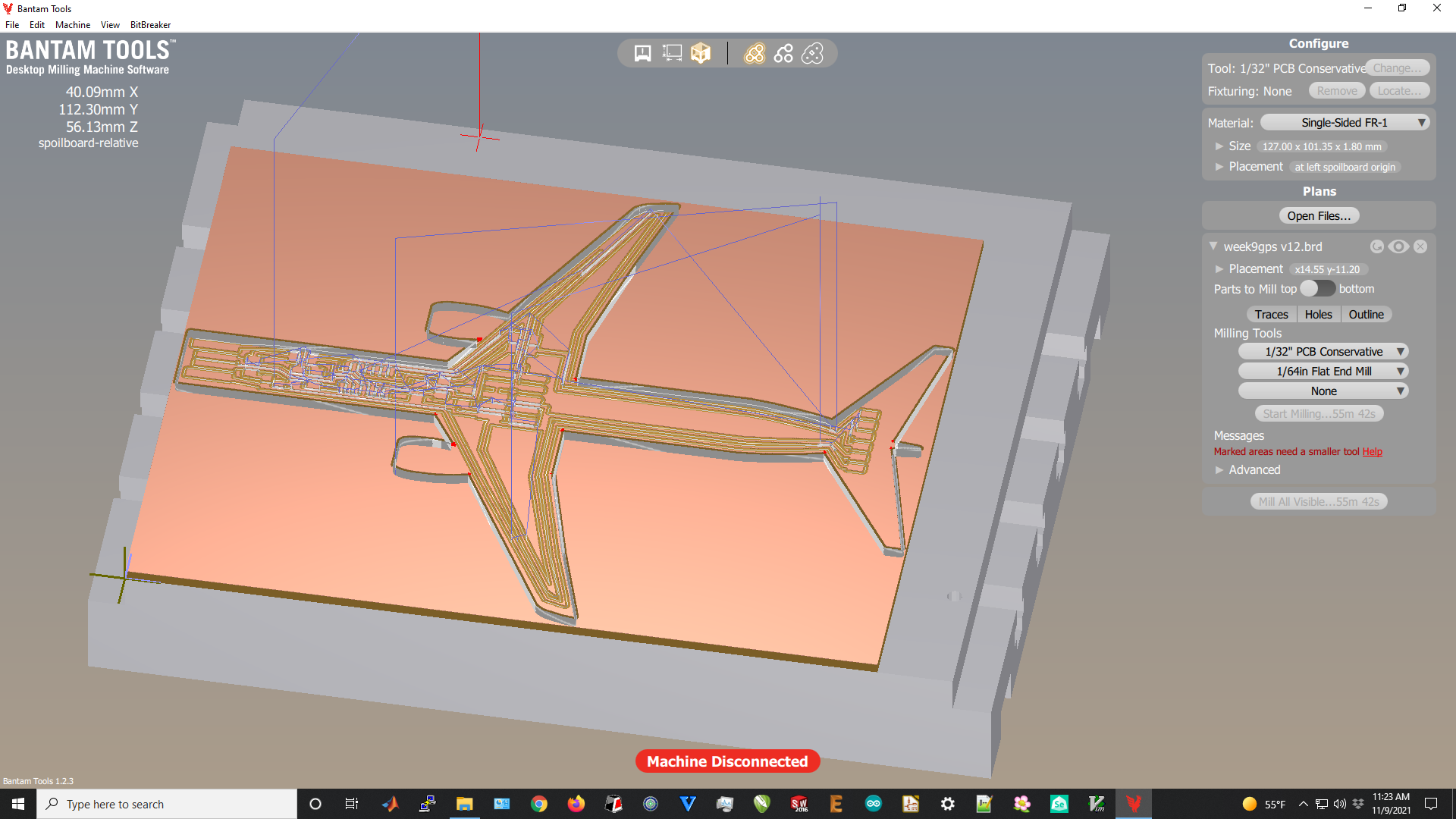
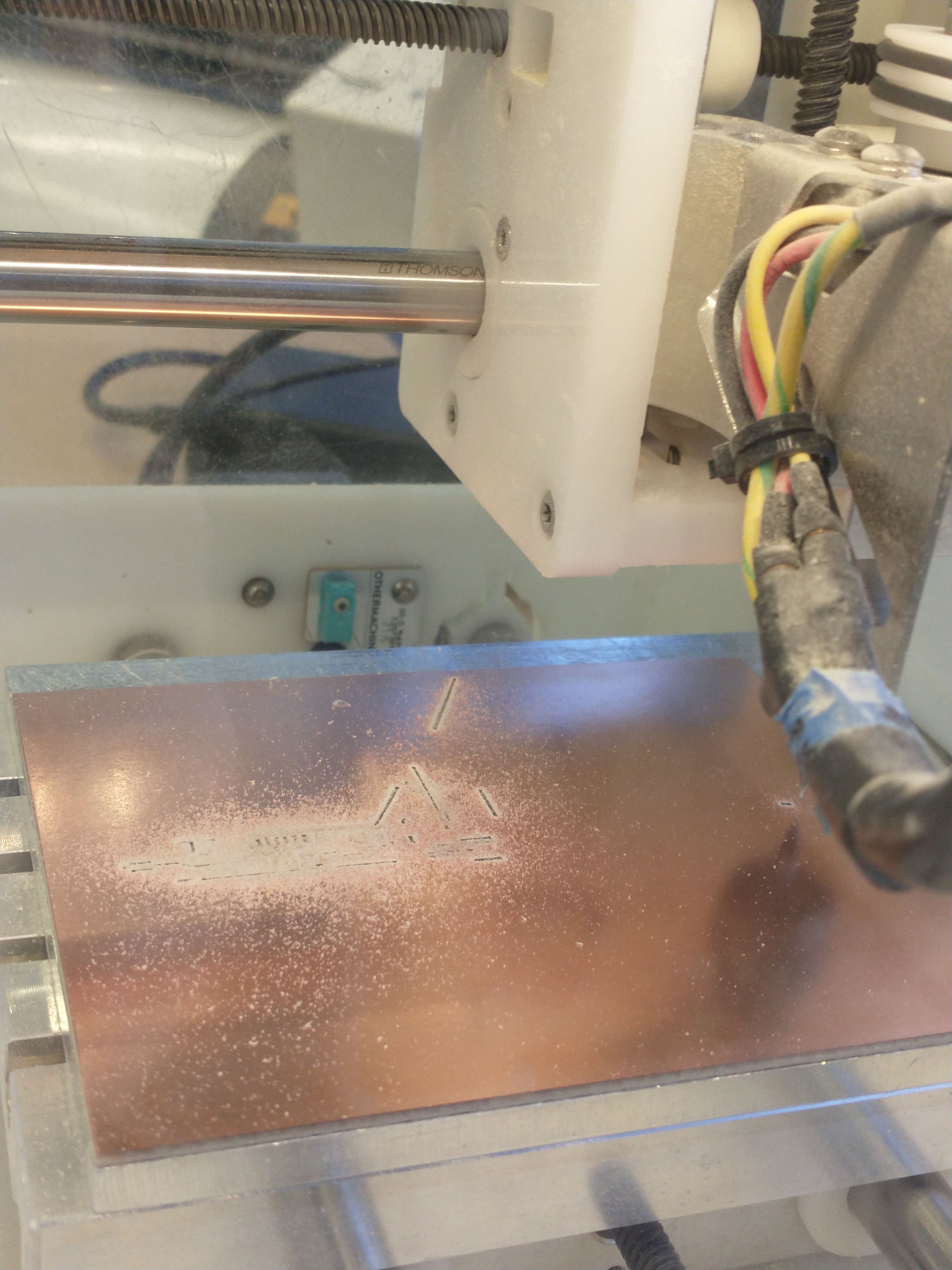
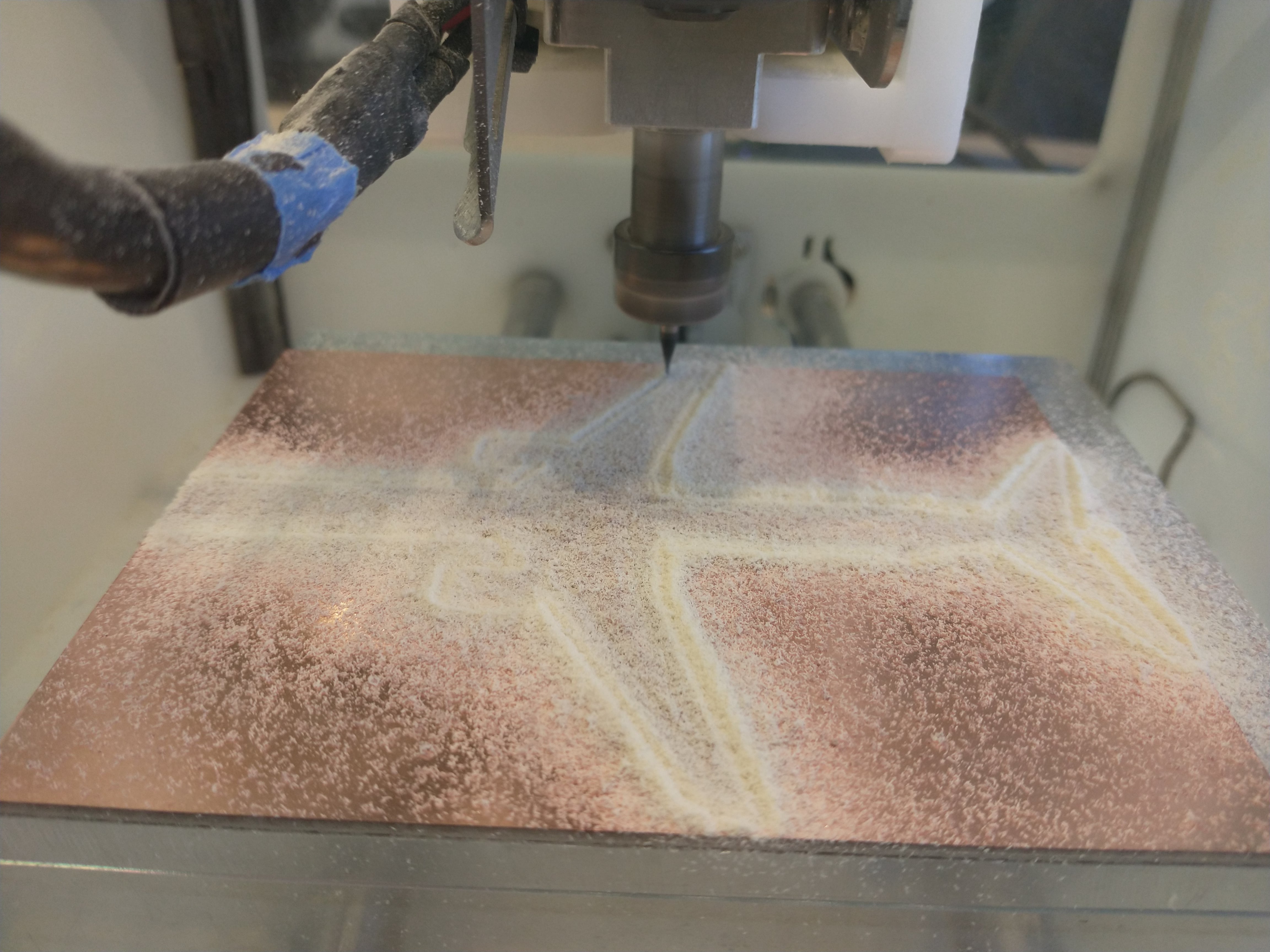
Note the 55 min 41 sec mill time. The Othermill milling process was the same as usual and even finished 15 minutes sooner than the estimated mill time.
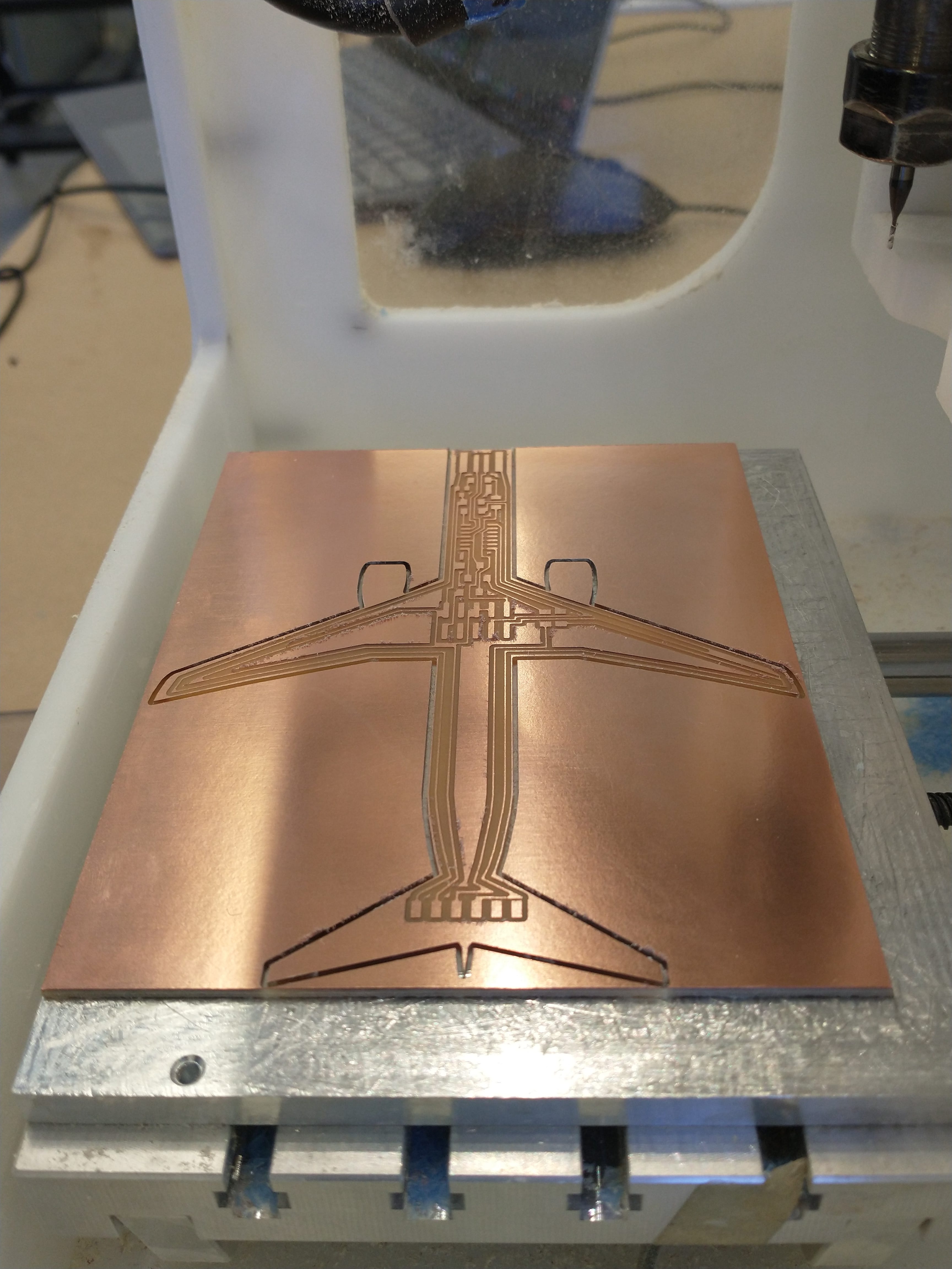
As usual, I used a spackle knife to clean up the PCB and an exacto knife to strip the leftover copper around the USB port.
Parts:
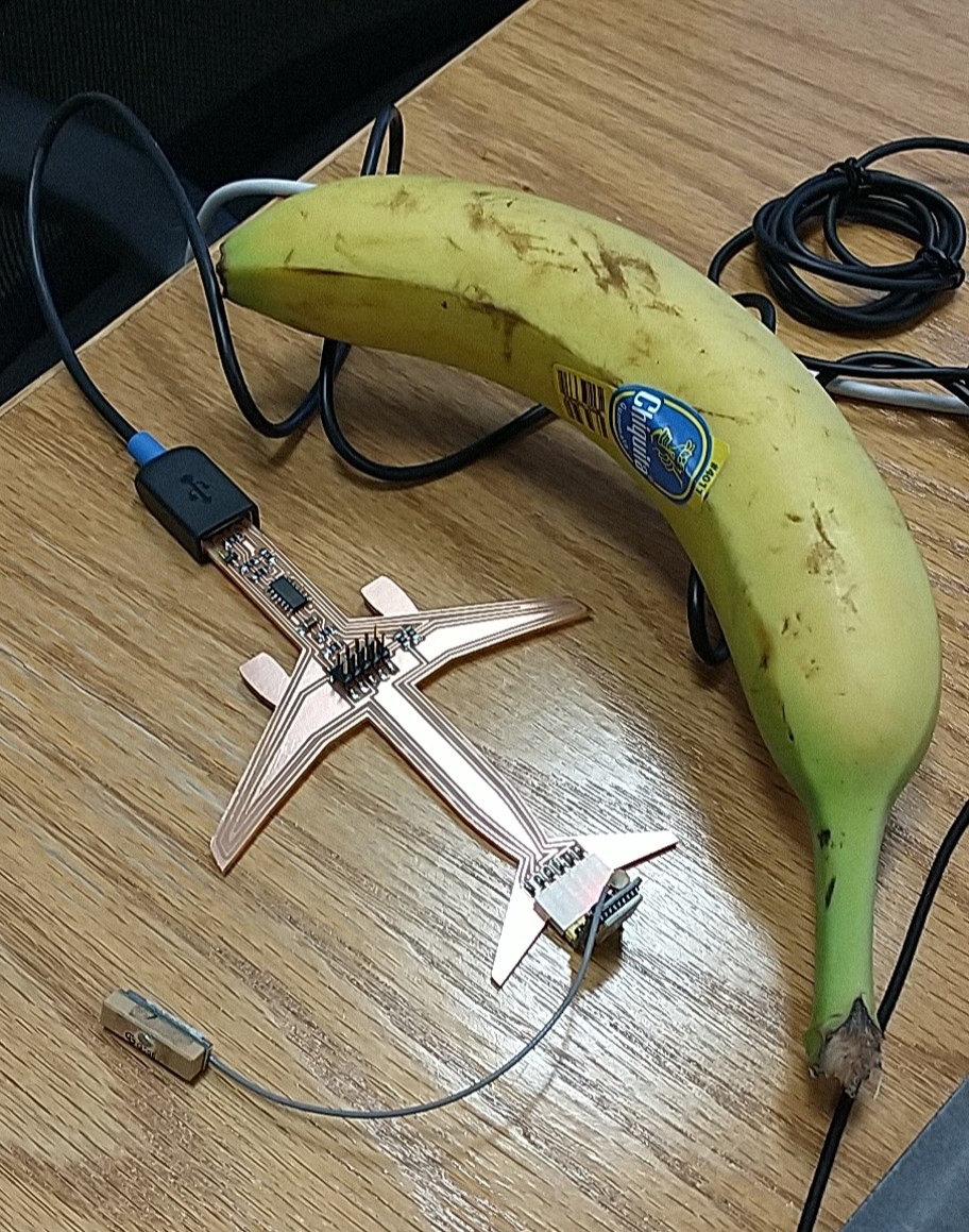
It turns out bootloading can be done through Arduino, thanks to Anthony for helping me do this. It turns out that TX of the GPS board needs to be connected to the RX of my plane - and similarly RX to TX - so I used a set of connectors to swap the two.
The 6.08 lab instructions and code template were incredibly useful, and I referenced Quentin's serial implementation (on using a SAMD as a serial USB bridge) to figure out that Serial2 was going to Pins 4 and 5, though I ended up not using the code itself.
Some additions I made to the code included commenting out the Hardware line and replacing GPs with Serial2 (ex: "gps.begin(9600,SERIAL_8N1,32,33);" to "Serial2.begin(9600);". I also changed the communication rate in the Serial Terminal to 115200 baud.

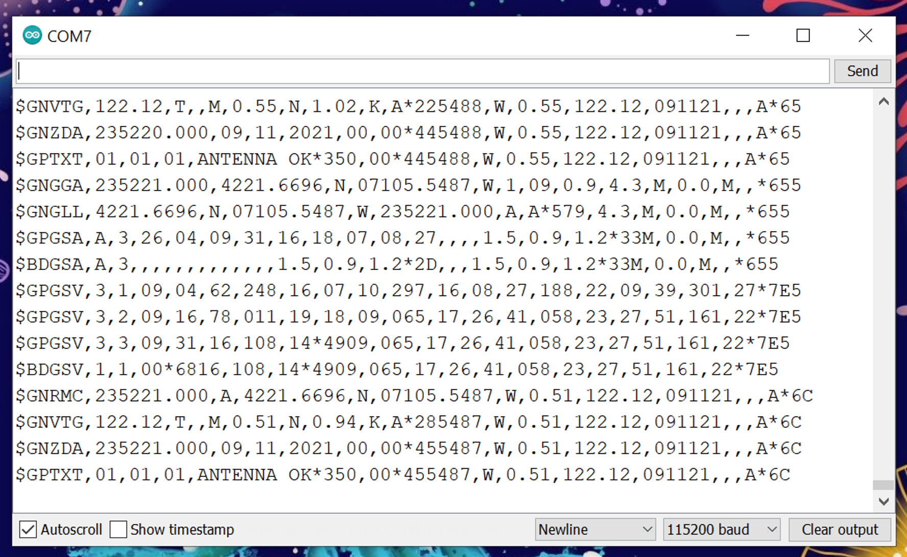
The red light on the GPS board will start blinking after the device locks onto satellite signals and begins processing and transmitting data. Data is calculated and reported for all satellite systems once every second. Each line corresponds to one satellite system, indicated by an identifier at the start of the line. GNRMC corresponds to GPS and BDGSA corresponds to Beidou. The rest of the information on each line is separated by commas and is as follows:

The coordinates of KBOS Terminal C are 42 deg 22' N 71 deg 01' W, which equivalates to 42.366666667 deg N and and 71.0166666667 deg W. The FAA airport map saves me the trouble (so far) of deciding on a centroid of the airport, since Terminal C lines up with one of the gridlines.
To determine distance between two points on Earth (i.e. my location from KBOS), I need the Great Circle formula. The second equation is more accurate to short distances (convert latitude/longitude values to radians - degrees*pi/180) and gives an answer in radians, which needs to be multiplied by 180*60/pi to get distance in nautical miles. This formula gives me 3.286315864987241 nm between KBOS and MIT (42.3601° N, 71.0942° W), which should be similar to what my code gives me.
I ran into trouble trying to extract the latitude and longitude data and outputting distance calculations, as it turns out that Arduino's implementation of printing floats seems to be "terribly unoptimized, broken, and all around bad." It takes an extra 6 kb just to print a float, which is apparently too much for the D11C microcontroller I'm using. So I'll figure this out another time.
Ideas for future work include 3D printing a case for the board (thanks Dave for the suggestion!), adding a display screen on top (so the "compass" can be handheld, especially if I plug the board into a portable battery pack), and adding my intials onto the engines.
Massive thanks to Anthony (especially with code debugging), Harrison for his help with schematic design and providing 6.08 materials, and Joe for letting me use a GPS sensor. Thanks to Alec for his debugging assistance, as well as to Ben and Shubhanga for helping me figure out what the data parsing code does exactly.