Week 5:
Electronic Design
I made a fetal mistake in Eagles... never mix up your VCC & VDD
Important Data:Ben is the HERO this week
So, there's no better way to start the documentation this week. The small mistake I made in schematics will cause a lot of pain,
confusion, and stress down the road.
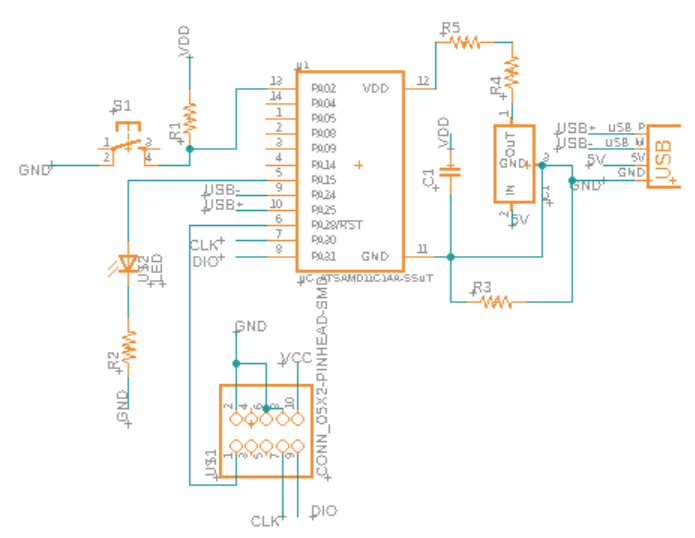
This is a rather simple design, I used a pull-up resistor and a pin to detect the state of the button and a pin to drive led.
The mistake, however, happened early on during the drawing of my schematics. Essentially, I accidentally use VCC for one of the programming
header pins while using VDD for the rest of the wires connecting to VDD on the microcontroller. This led to two unexpected artifact in my PCB
routing.
1) The capacitor was not connected directly to VDD (it was connected pull-up resistor (1k ohm) and then VDD). SAMD11 was not happy about the lack
of power conditiong. The programer board could not detect the correct voltage from the board due to this (it was detecting 1.1-1.3V instead of 3.3V)
2) On top of VDD/VCC confusion, I did not name the VDD on microcontroller as "VDD", this is the exact reason why programmer wasn't happy.
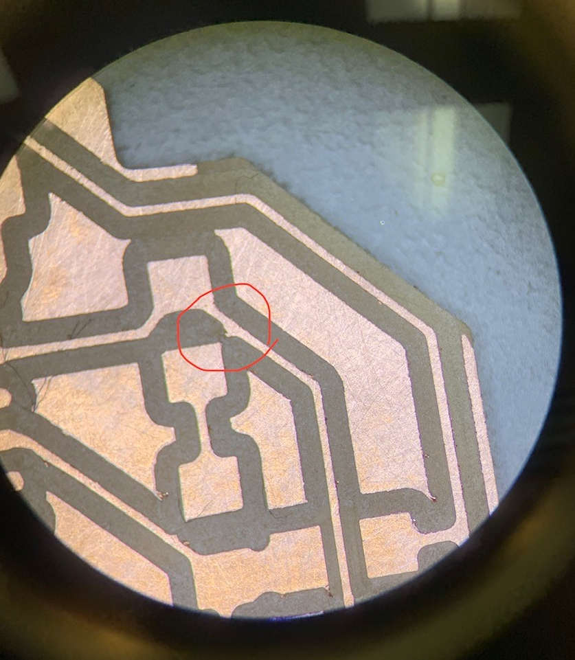
3) The pin that was named VCC just wasn't connected to VDD on the microcontroller. This is the easier fix and was spotted quickly.
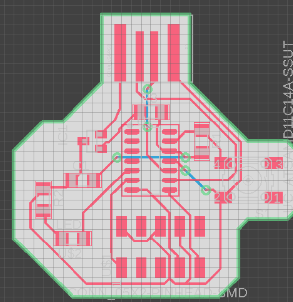
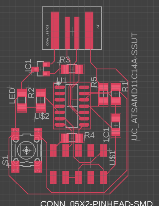
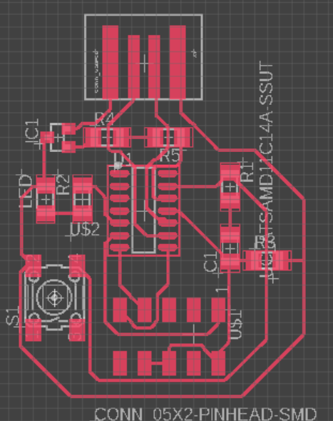
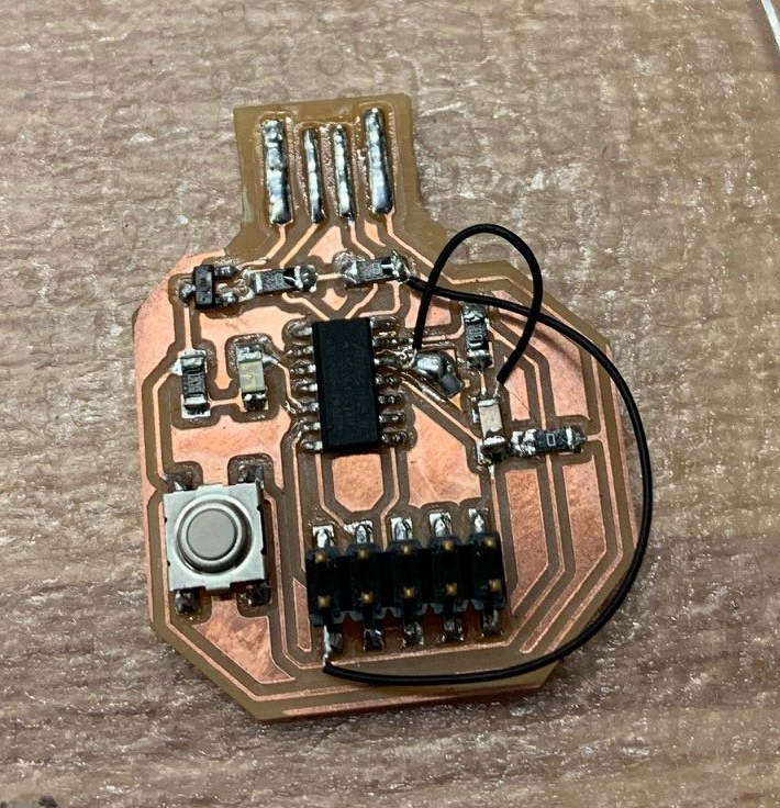
The designs evolved from left to right. (Note, all of them have the VCC/VDD defect.) In my first try, I did it without too much thinking and utilized the auto routing function from Eagles. It produced somewhat ok restuls, but has the need for 3 vias. After some thinking, I decided to leave that behind and basically replaced vias with jumper. However, this time, I forget to load the desigh rules first and had very thin traces (6 mil). This, thankfully caught by Anthony, would have failed miserably. For example, I do not have the luxury to sneak two traces under on jumper. The design on the left is what I end up milling and running into troubles during testing stage (flashing bootloaders).
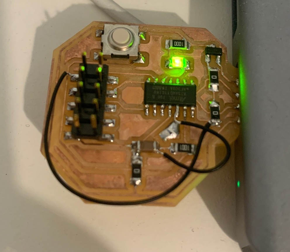
Finally, the programming is done and this works! However, the simple program I wrote can not deal with the button debouncing issue. It is evident in the push counted. For example, the microcontroller would count about 20 pushes whenever I press the button once. Writing this at 11:47, I might not have time to fix this...
Today I Learned:
1) I need to have better time management (I blame the long weekend). I wanted to try better designs, but debugging took up majority of my time.
2) Do NOT, under any circumstances, mix VCC with VDD. They don't mix well. Always double check your wiring and label to save you some pain down the road.