Guiding Questions
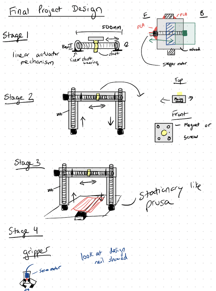
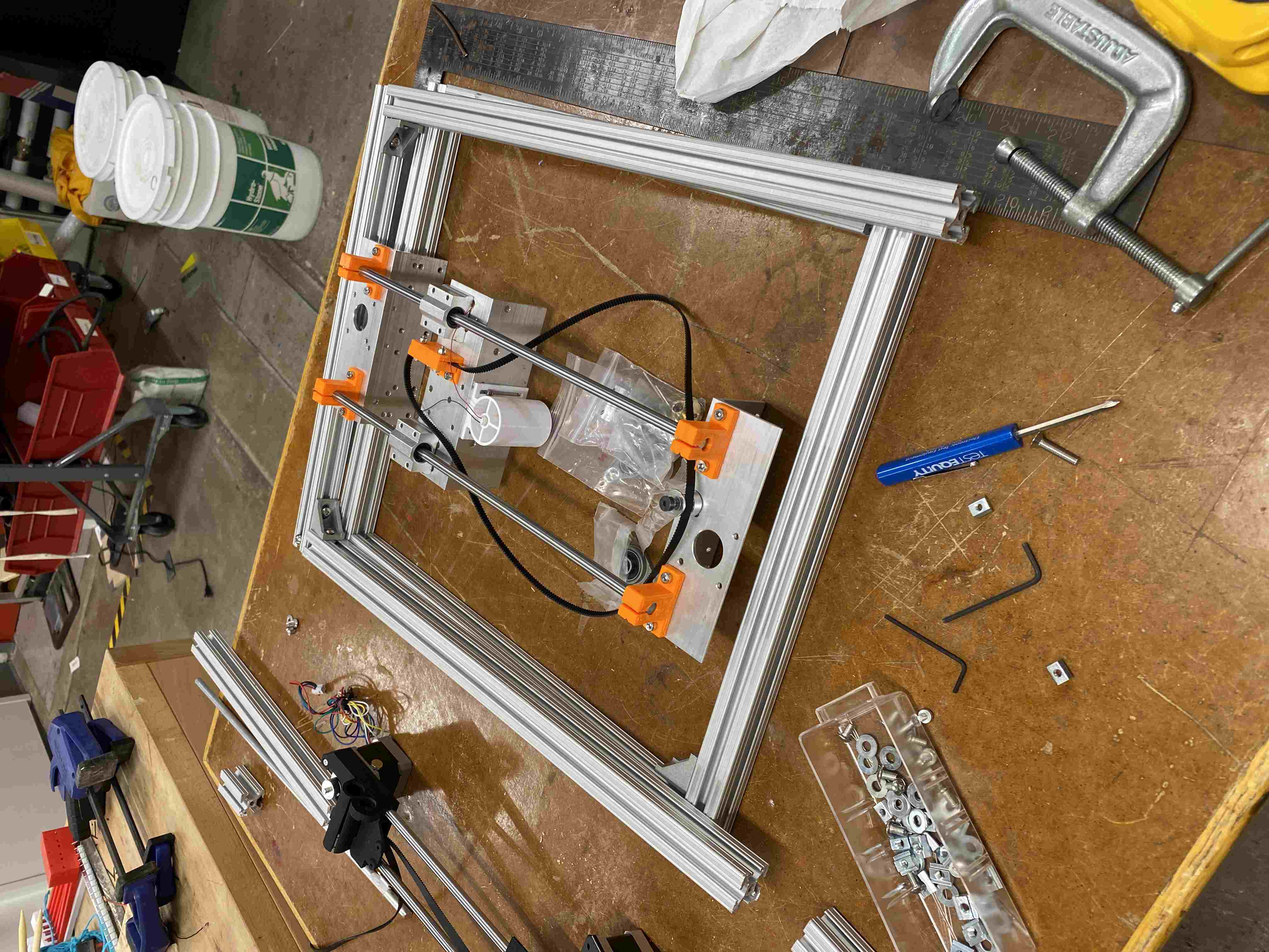
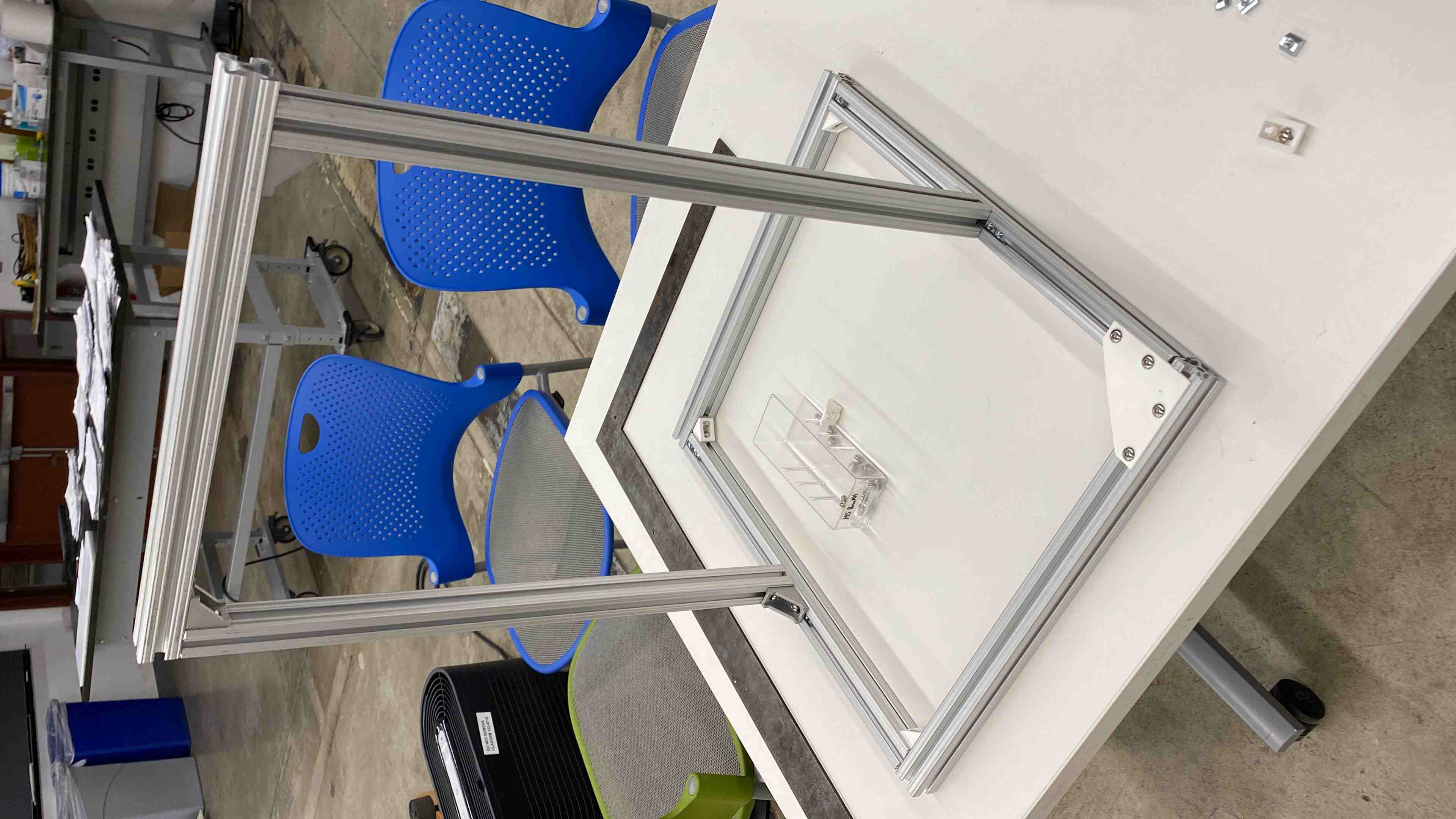
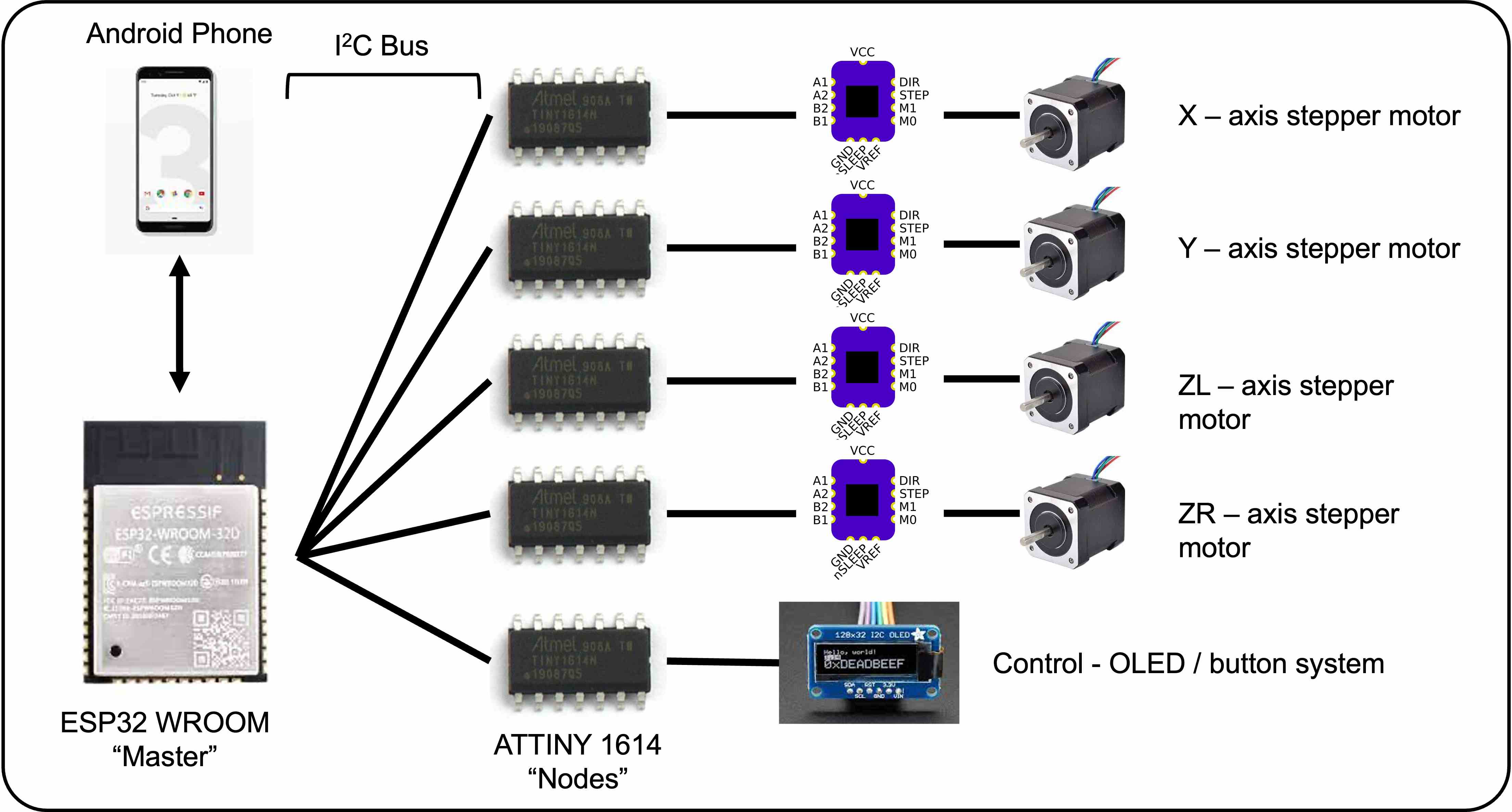
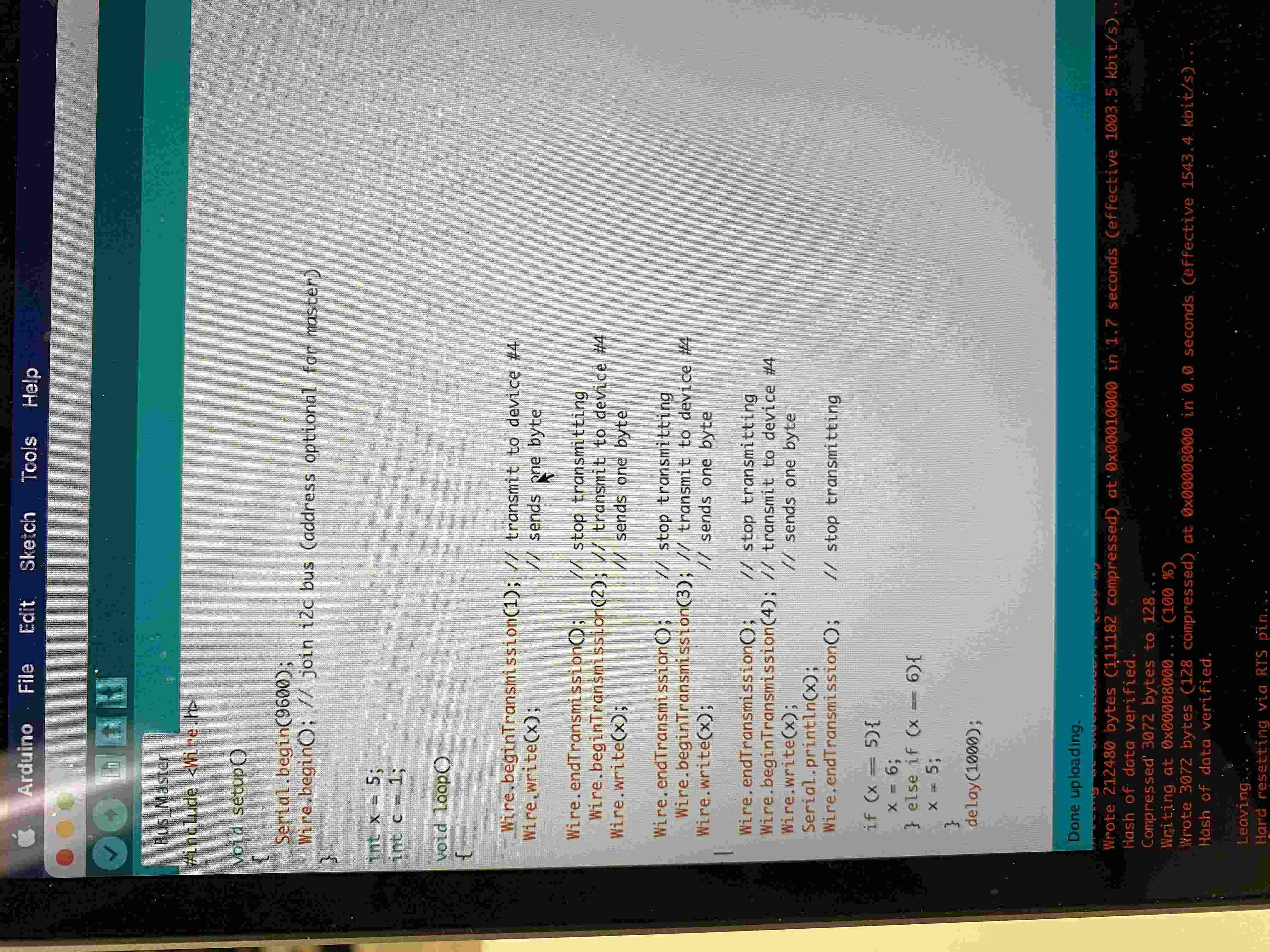
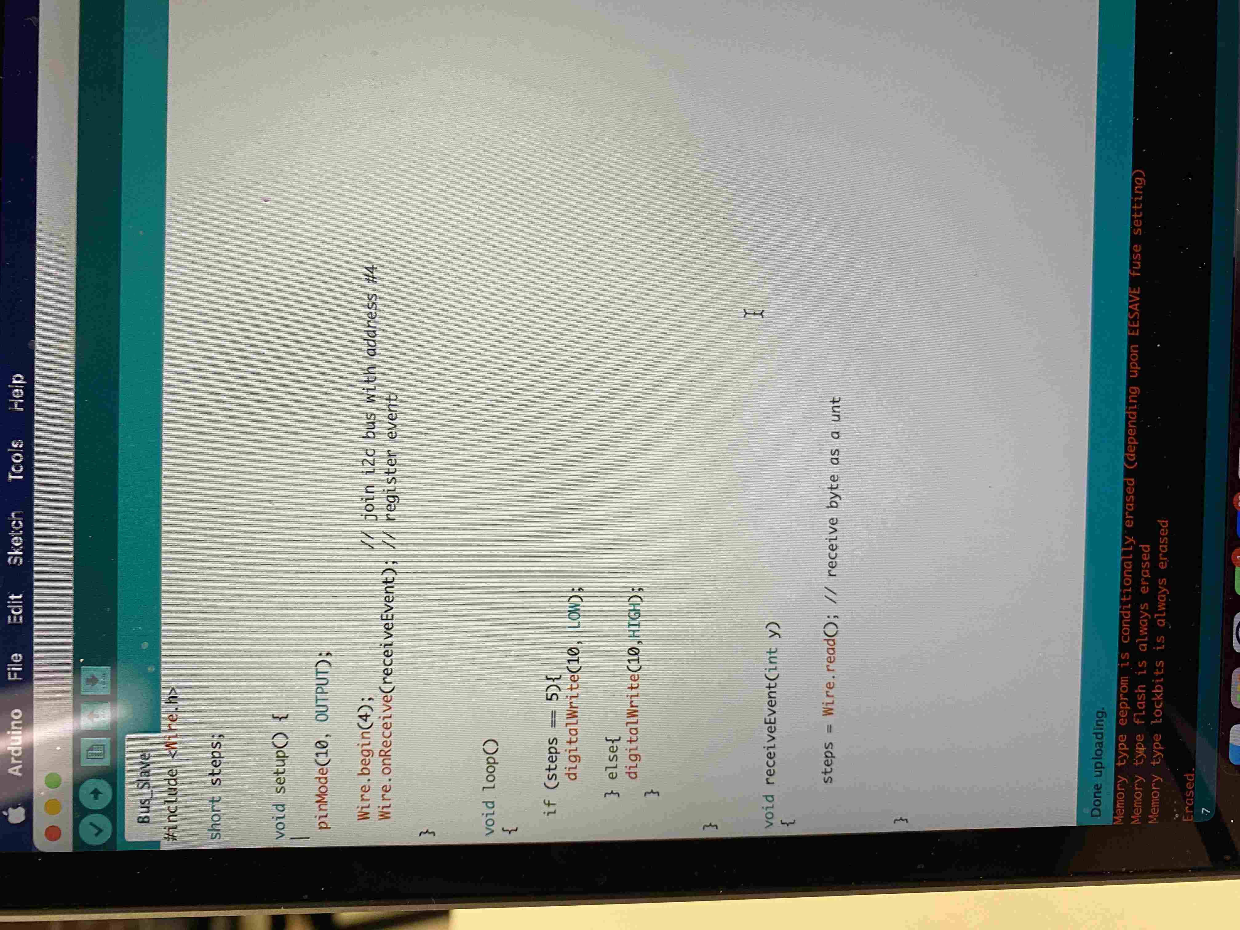
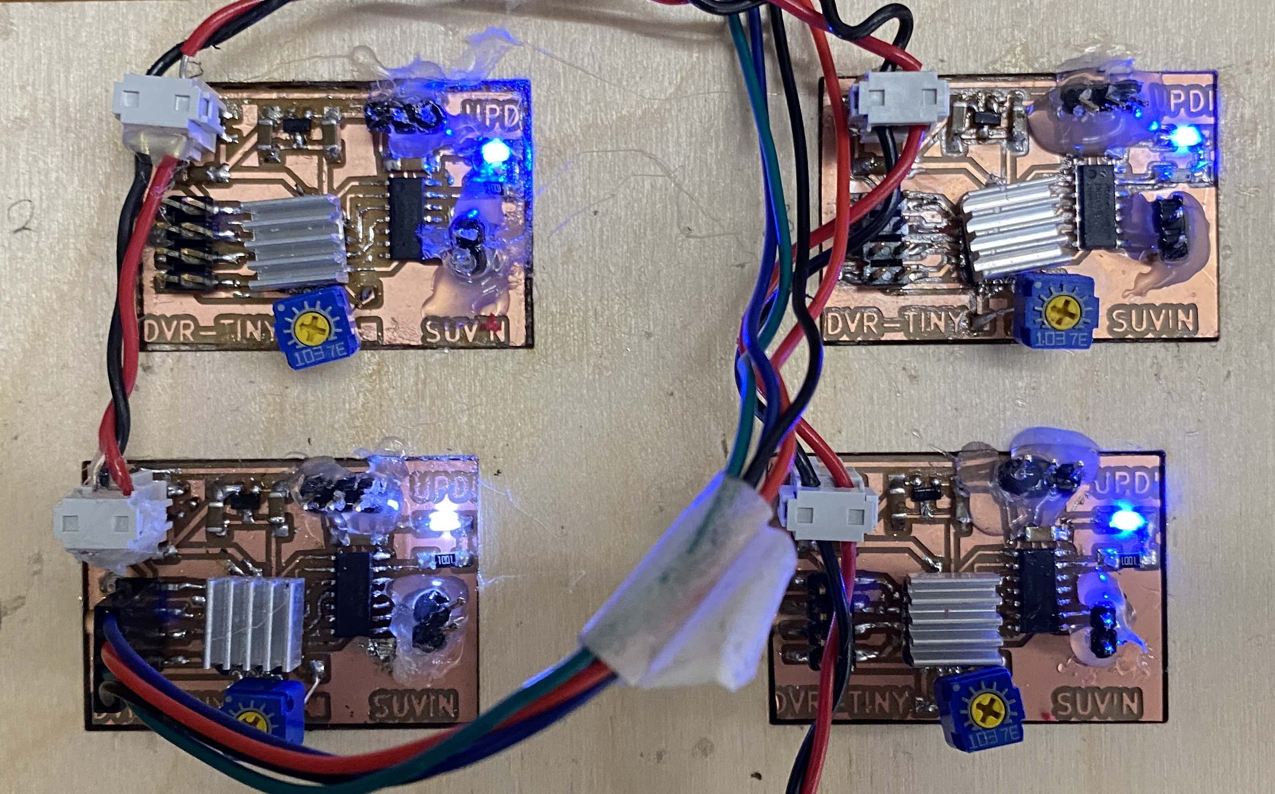
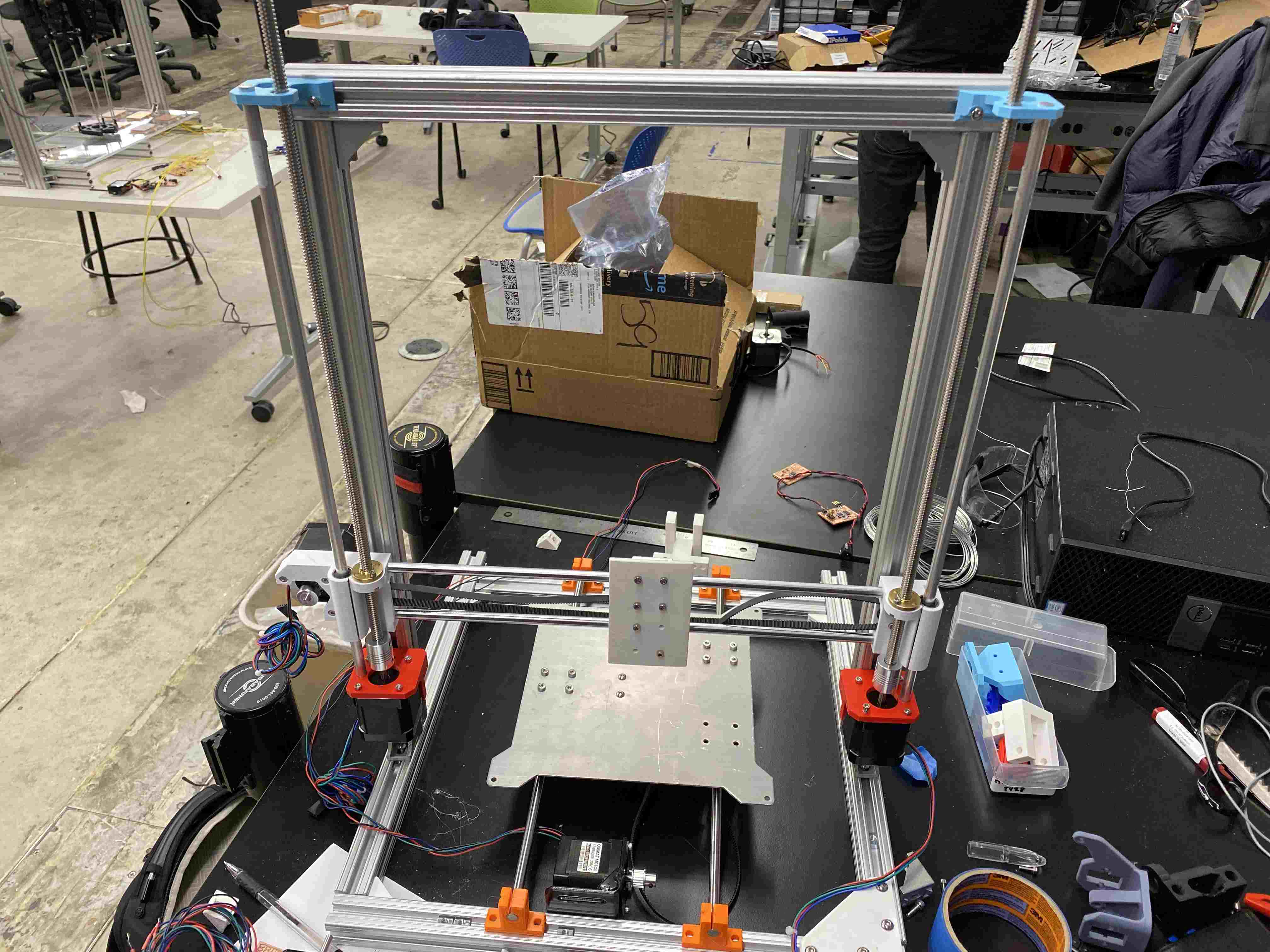
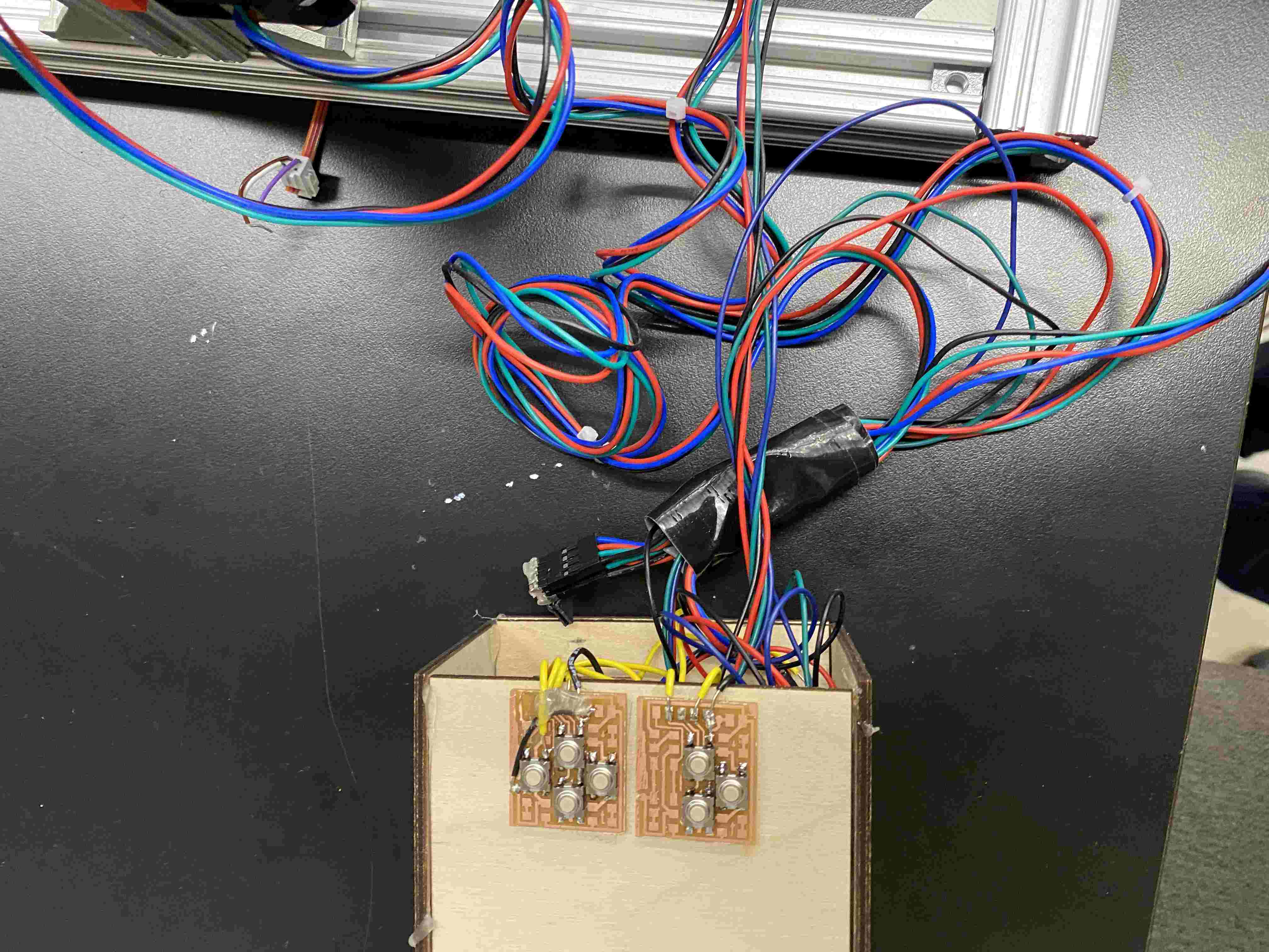
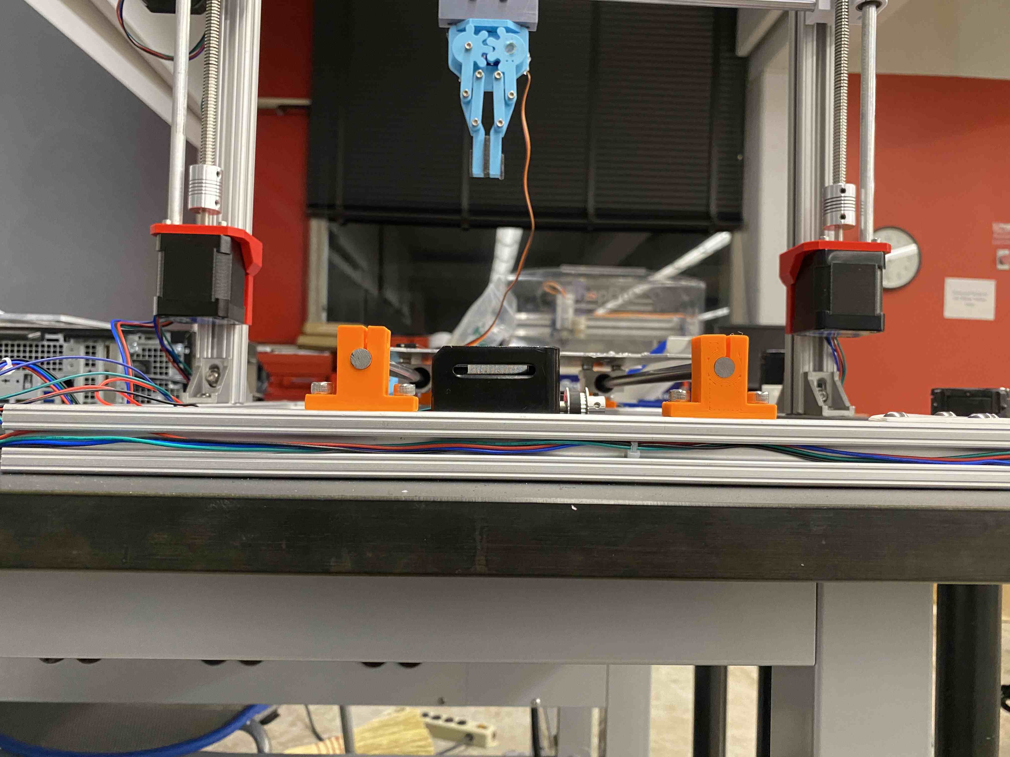
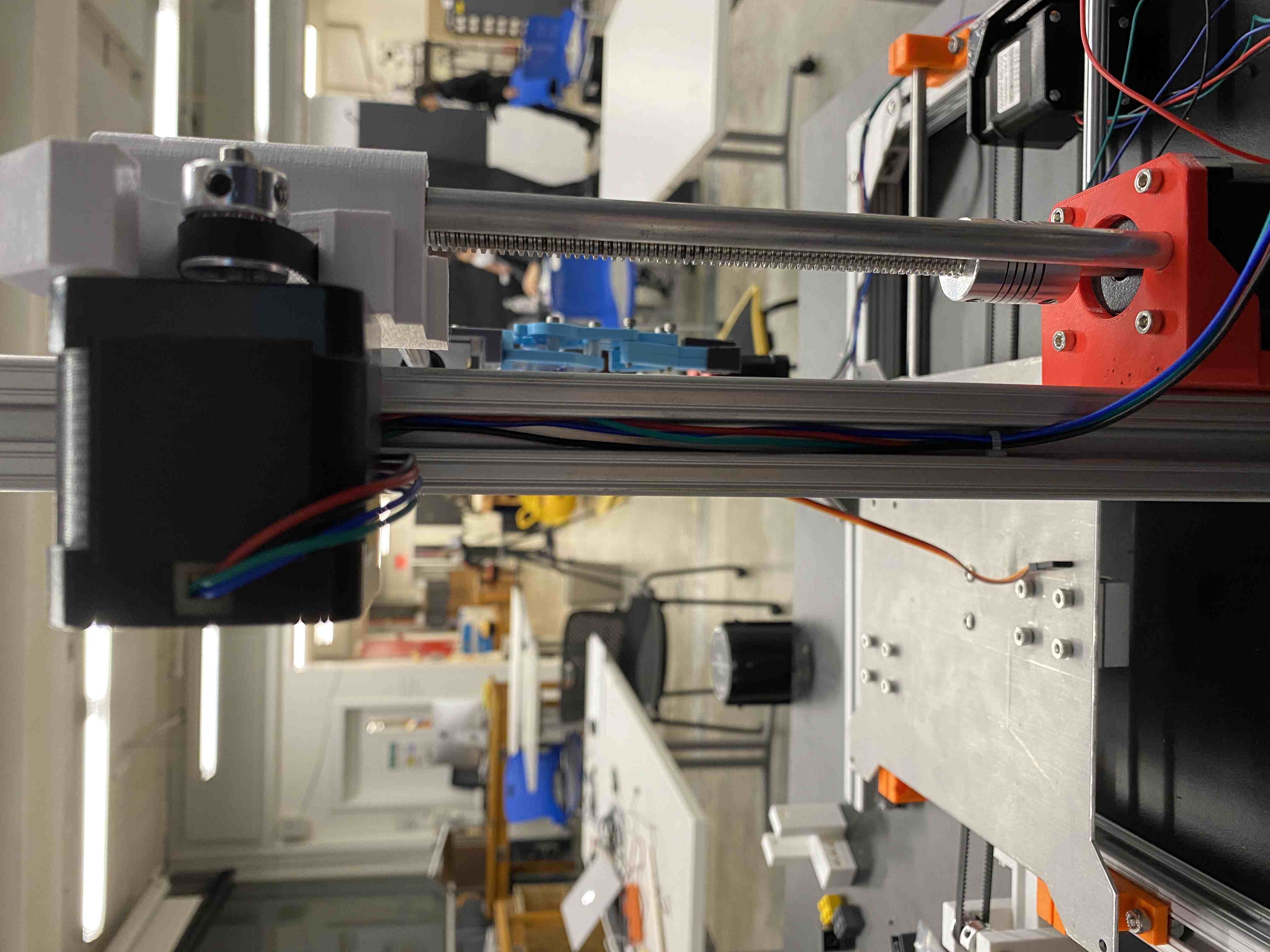
[1] What does it do?This is a 3-axis system that can be utilized to stack LEGO three-stud tall bricks togeher in a linear fashion. Using a set of 4 stepper motors - one for x, one for y, and two for z (stability), the motors can be coordinated using a series of custom ATTINY-DVR breakout boards that are directly integrated into the PCB. This machine can be refurbished as a multifunctional printer with various properties in the futuer, and this machine is built upon those principles using several removable joints, parts, and no glue/epoxy.
[2] Who's done what beforehand?
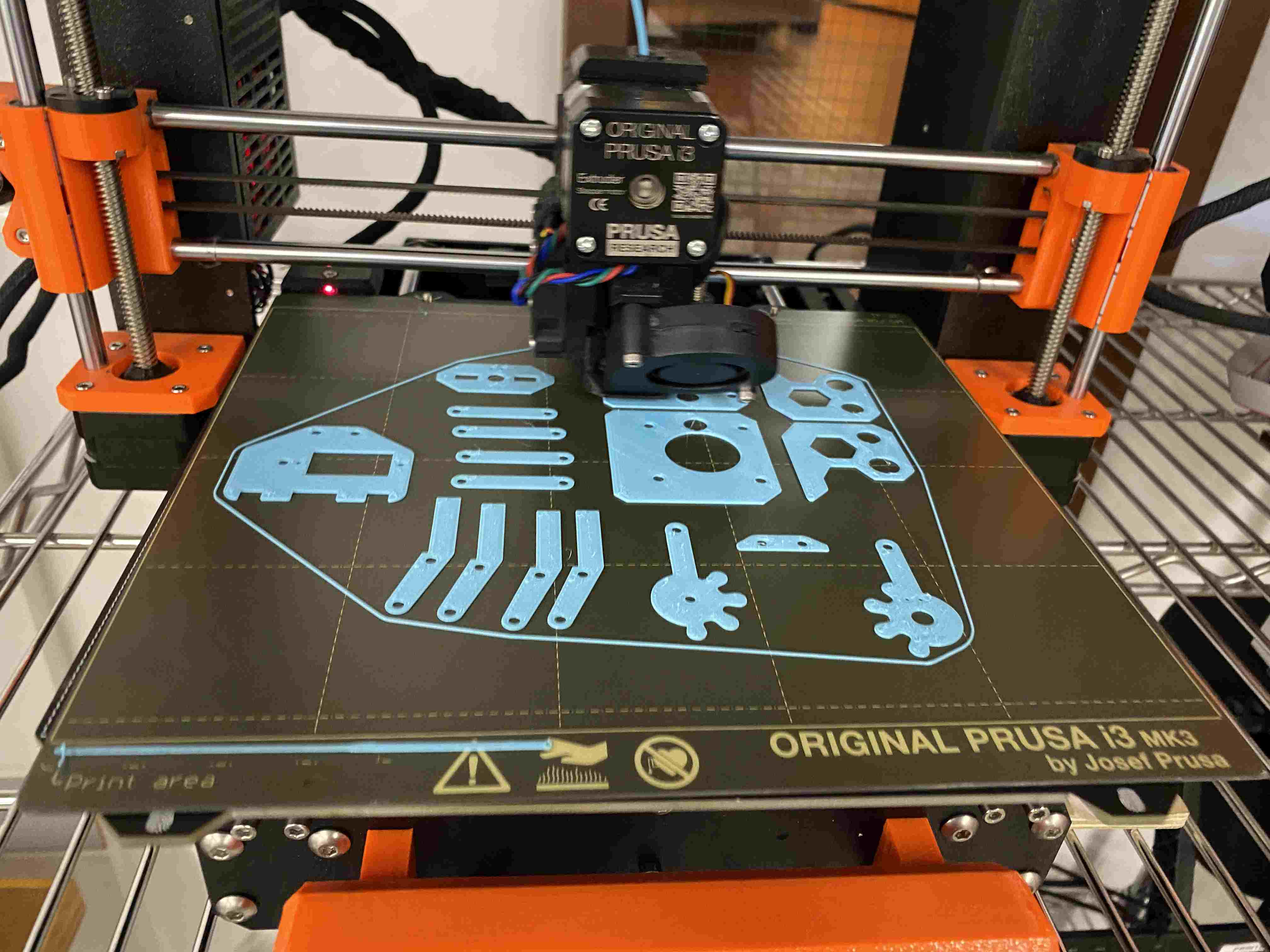
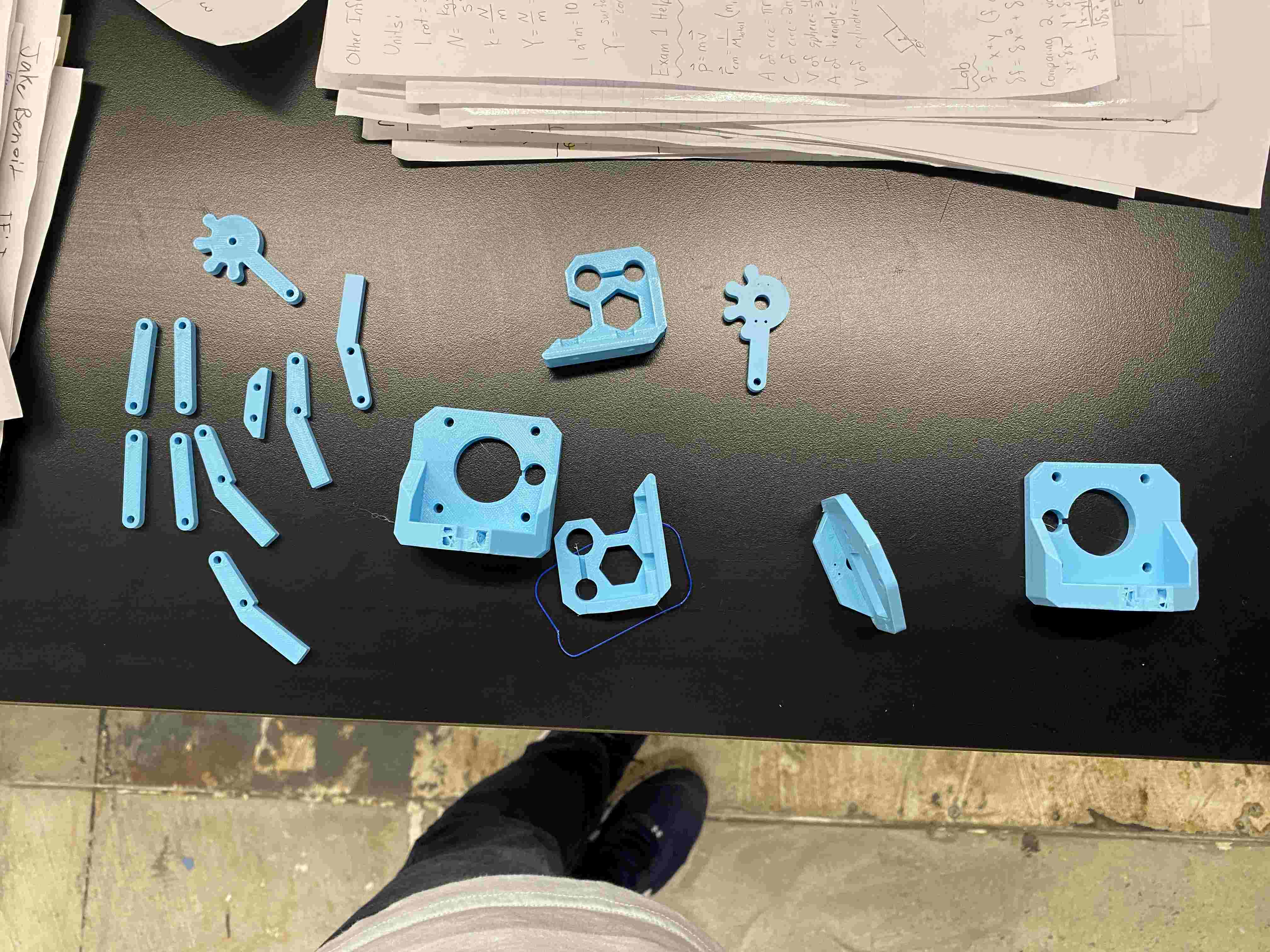
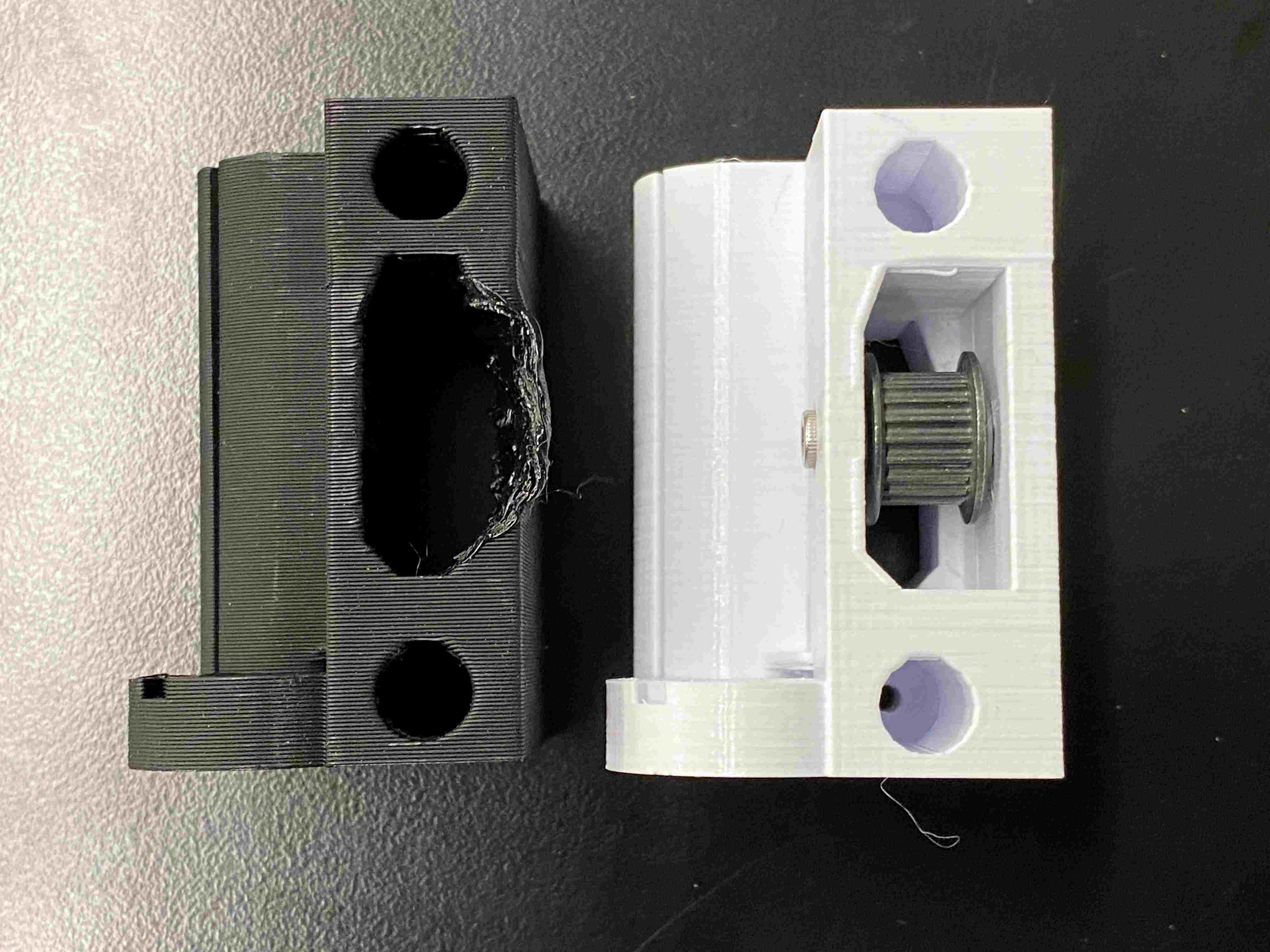
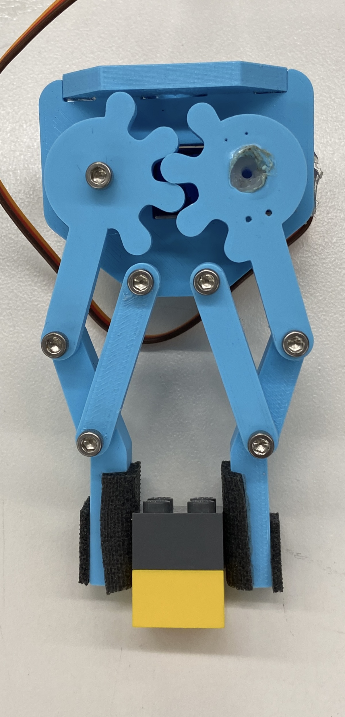
For the first part, the 3 axis machine. several companies already employ this through a variety of machines - this is the stable of the majority of items that make our world run. The most similar example would be 3D printers, and this similarity allows me to understand how these machines work as I build them. The frame, clank, and the belt system have been designed, but I want to challenge myself by making these files. In addition, the basic linkages of the gripper mechanism were predesigned. I found a metal sheet from a previous machining week class to ease my workload. The second part, the easy to exchange end-effector, is something less companies have focused on, so I made a system that was easily adjustable with screws for now so I maintain tightness while I experiment with magnets later on.
[3] What did you design?
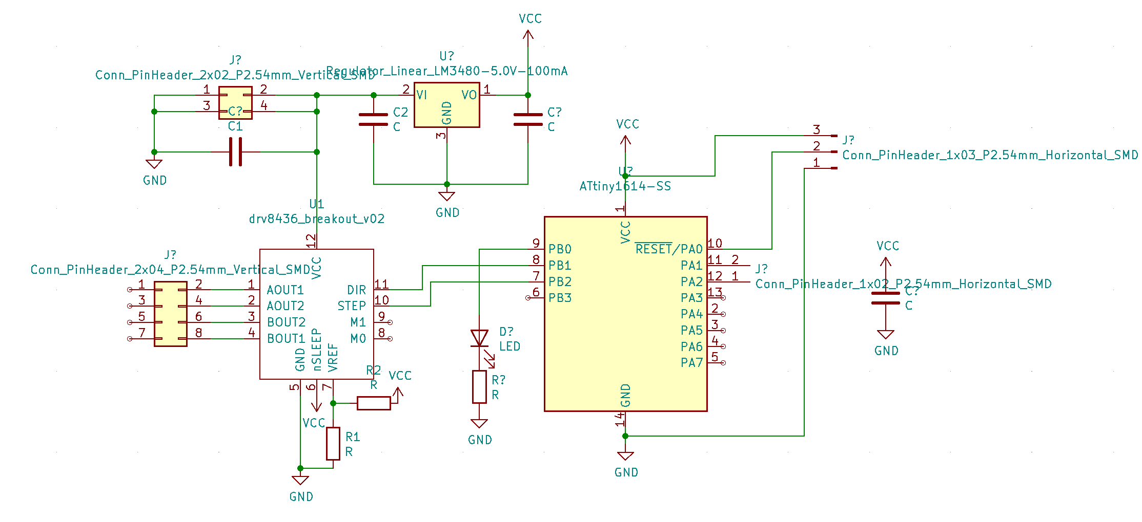
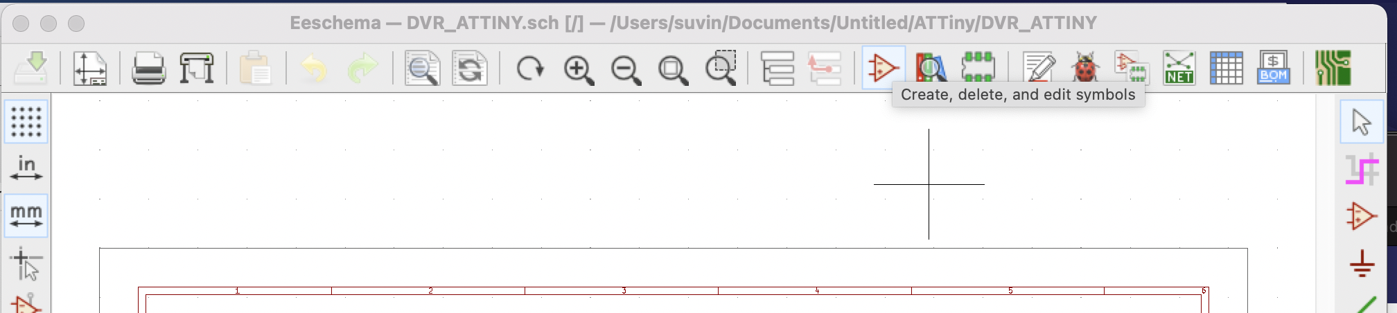
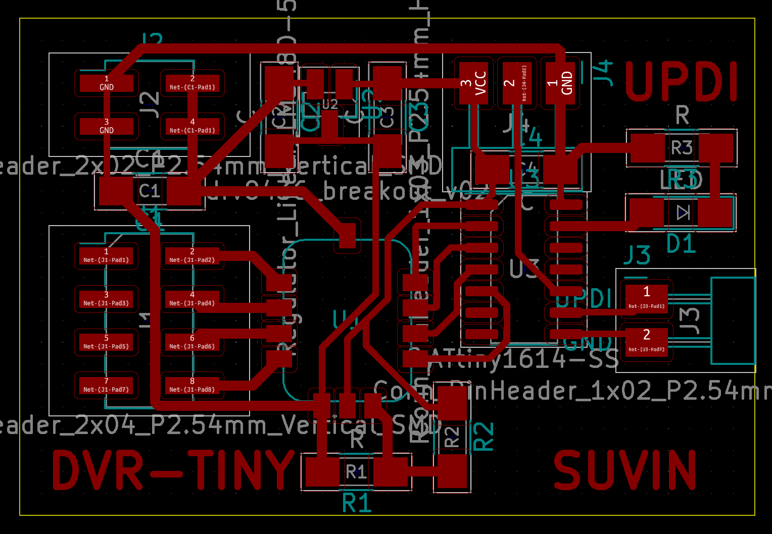
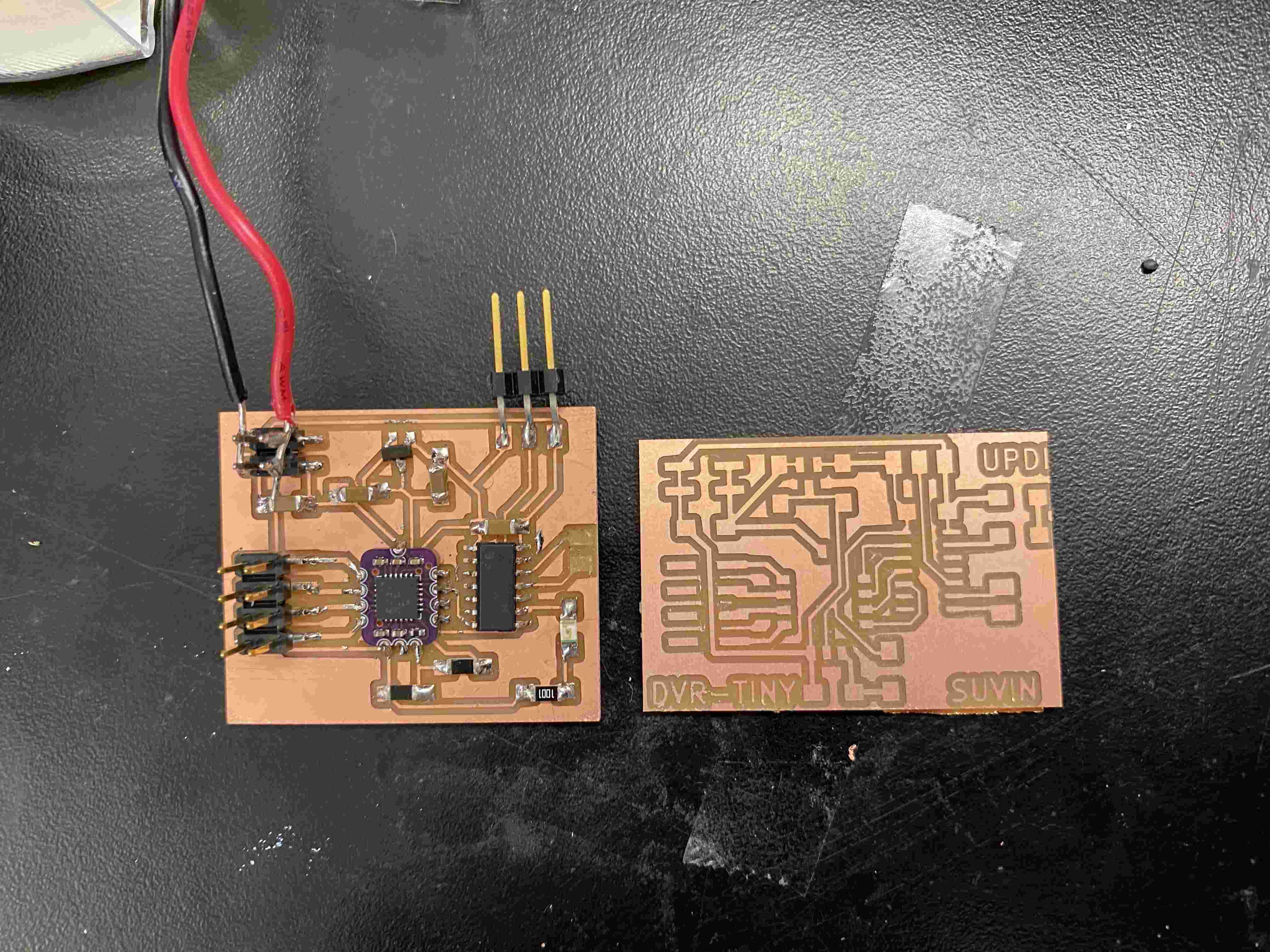
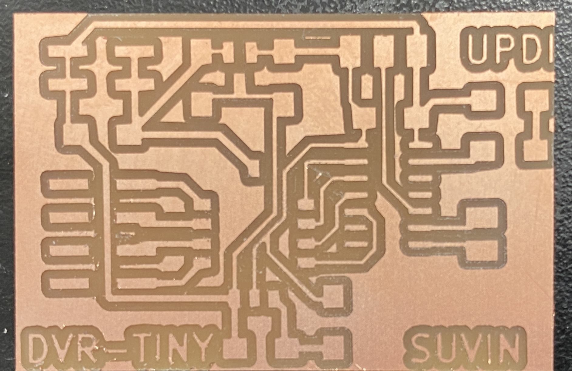
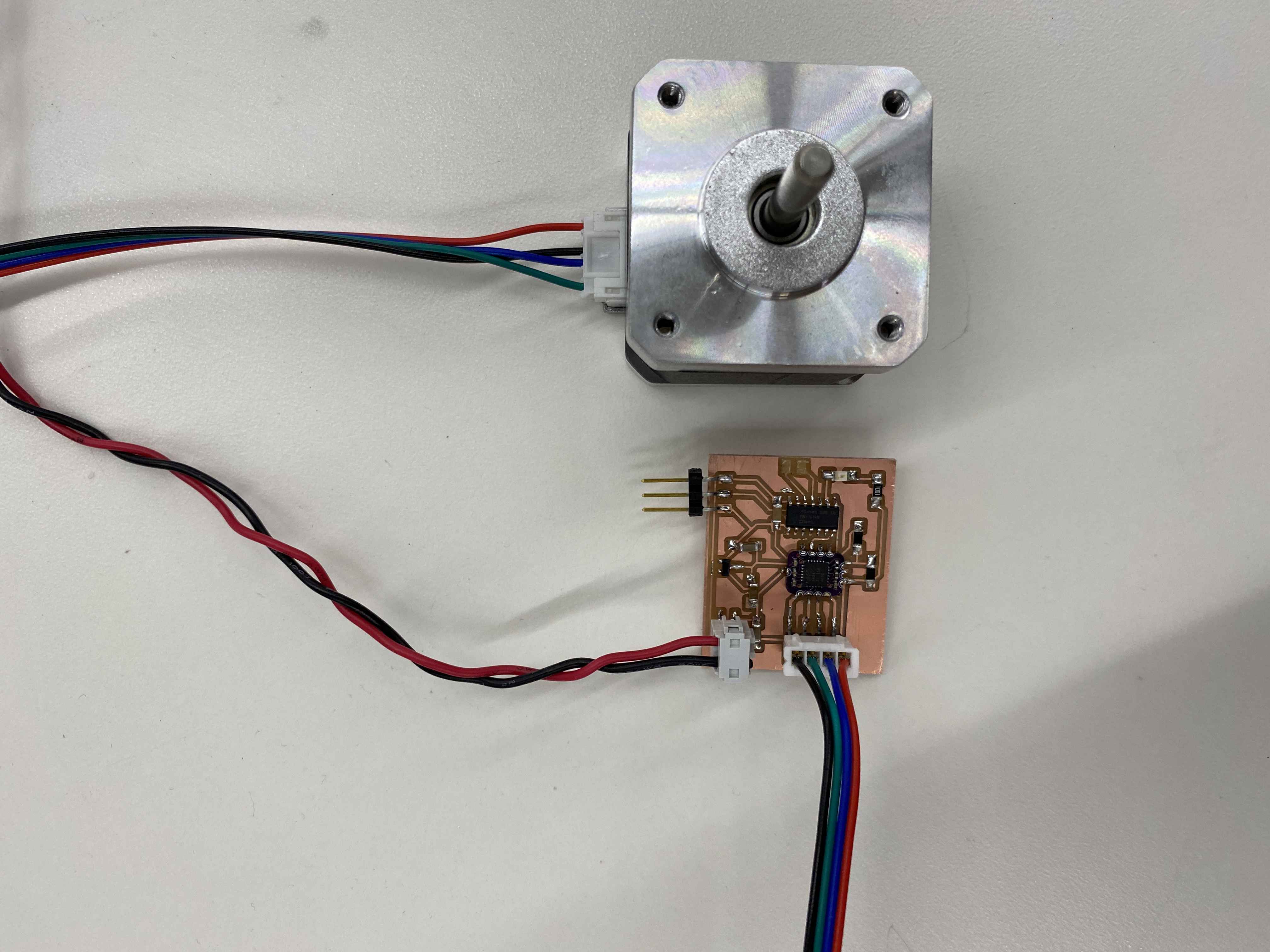
I designed the linear actuators, the idler 3D prints, and the most significant contribution will be the PCB boards. These are custom PCB boards using Zach's new "Baa" chips, and over the course of four weeks I have been able to master them to be able to microstep very effectively.
[4] What materials and components were used? [5] Where did they come from? [6] How much did they cost?
| Material | Source | Cost |
|---|---|---|
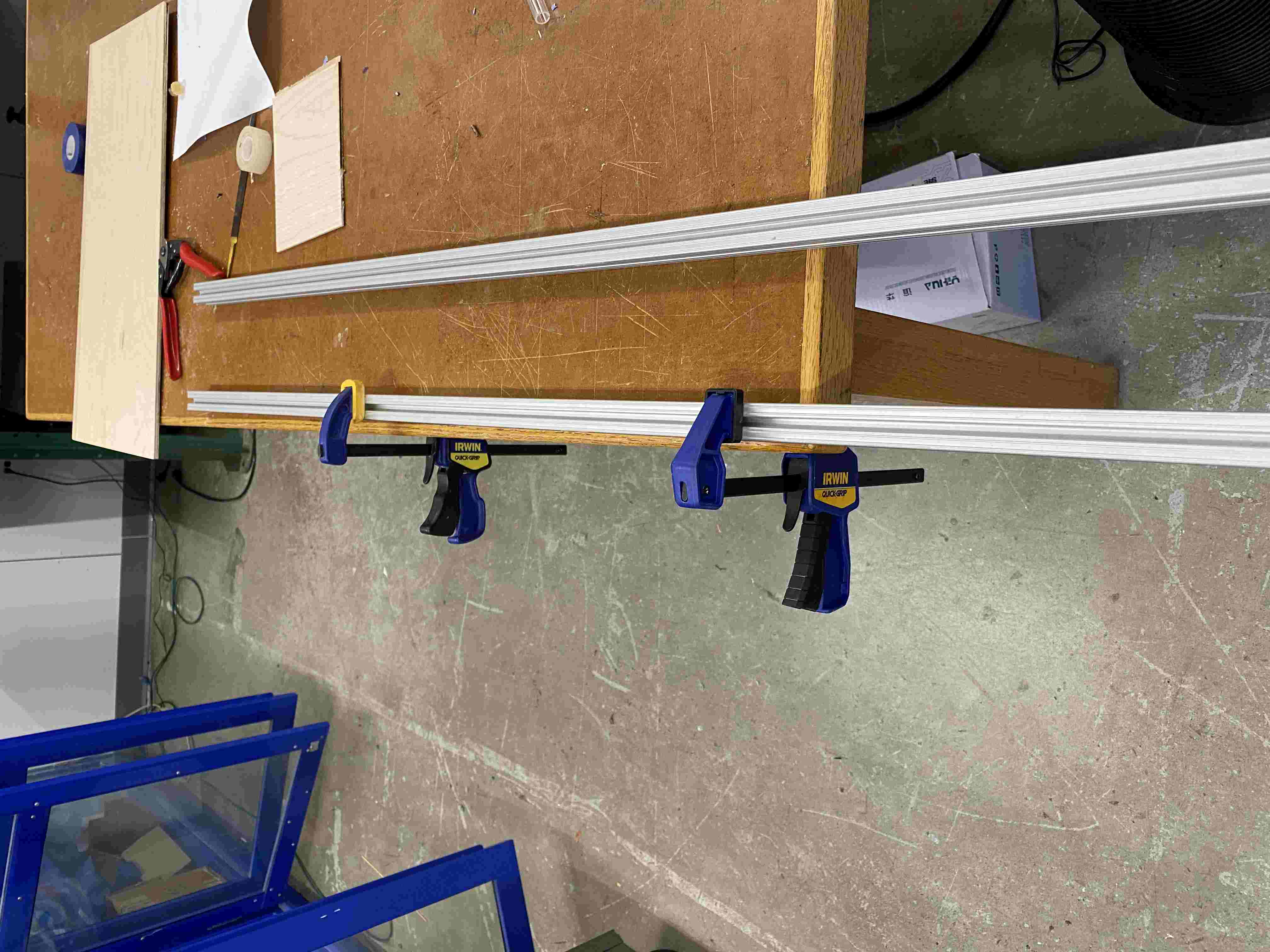
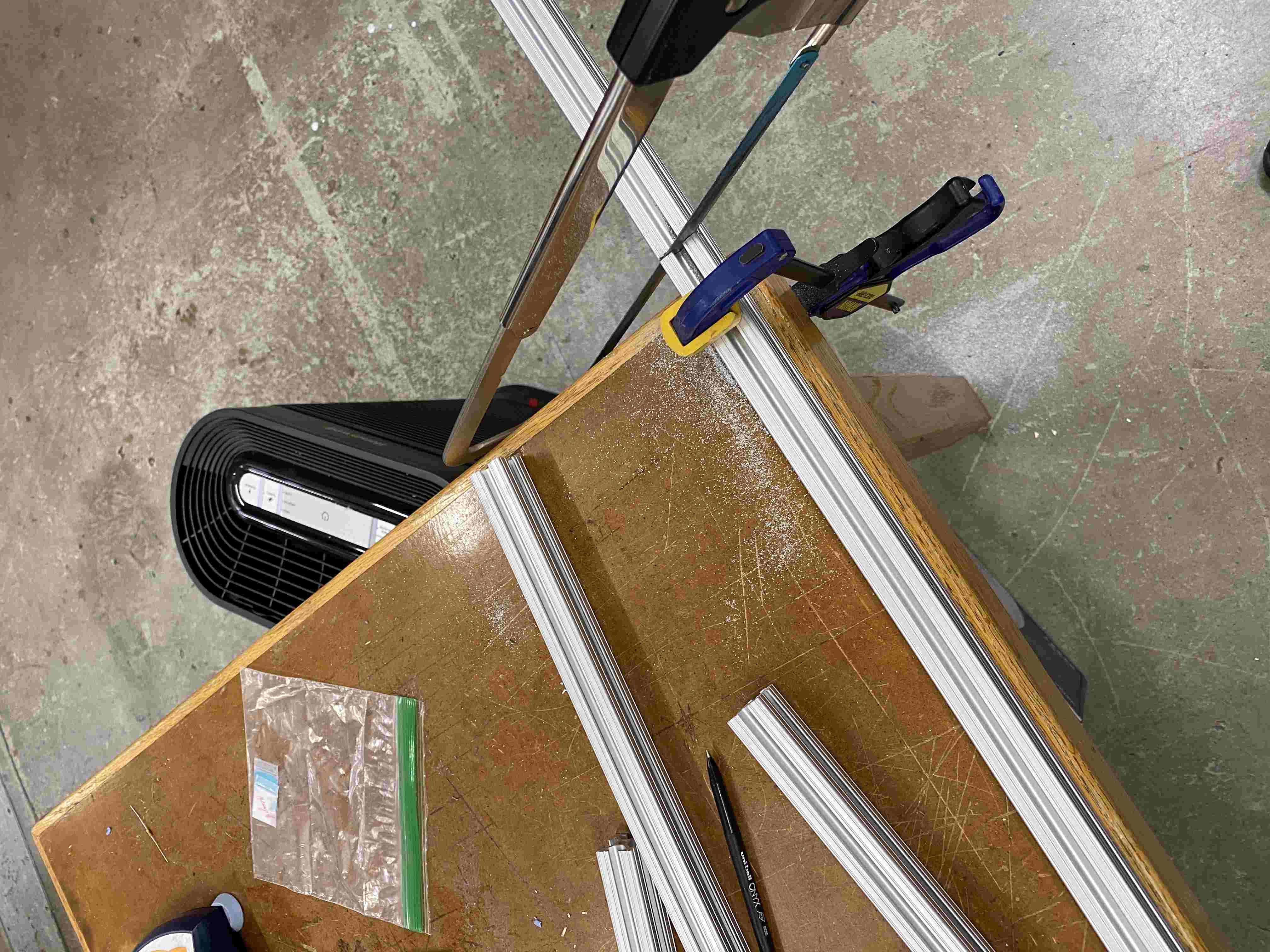
| 8' by 1" Aluminum T-Slotted Framing Rails | McMaster-Carr | $33.64 |
| 8 M3 x 8mm x 30mm Socket Screws | McMaster-Carr | $2.10 |
| 30 M4 x 15mm Socket Screws | McMaster-Carr | $5.20 |
| 8 x 2 Hole Inside Corner Bracket Gusset | Amazon, Boeray | $3.99 |
| 4 x NEMA 17 17HD48002H-22B Stepper Motors | Amazon | $44.00 |
| Servomotor 130 RPM - 6VDC | Digikey | $5.61 |
| Spool of PLA | MakerBot | $17.99 |
| 8" Square Metal Sheet | Amazon | $7.21 |
| 4 x DVR 8434 Fabricated Breakout Drivers | Zach Fredin | $4 |
| 2 x T8 Brass Nut | Amazon, Akkacm | $1.00 |
| 2 x 500mm Tr8X2 Lead Screw | Amazon, Akkacm | $24.99 |
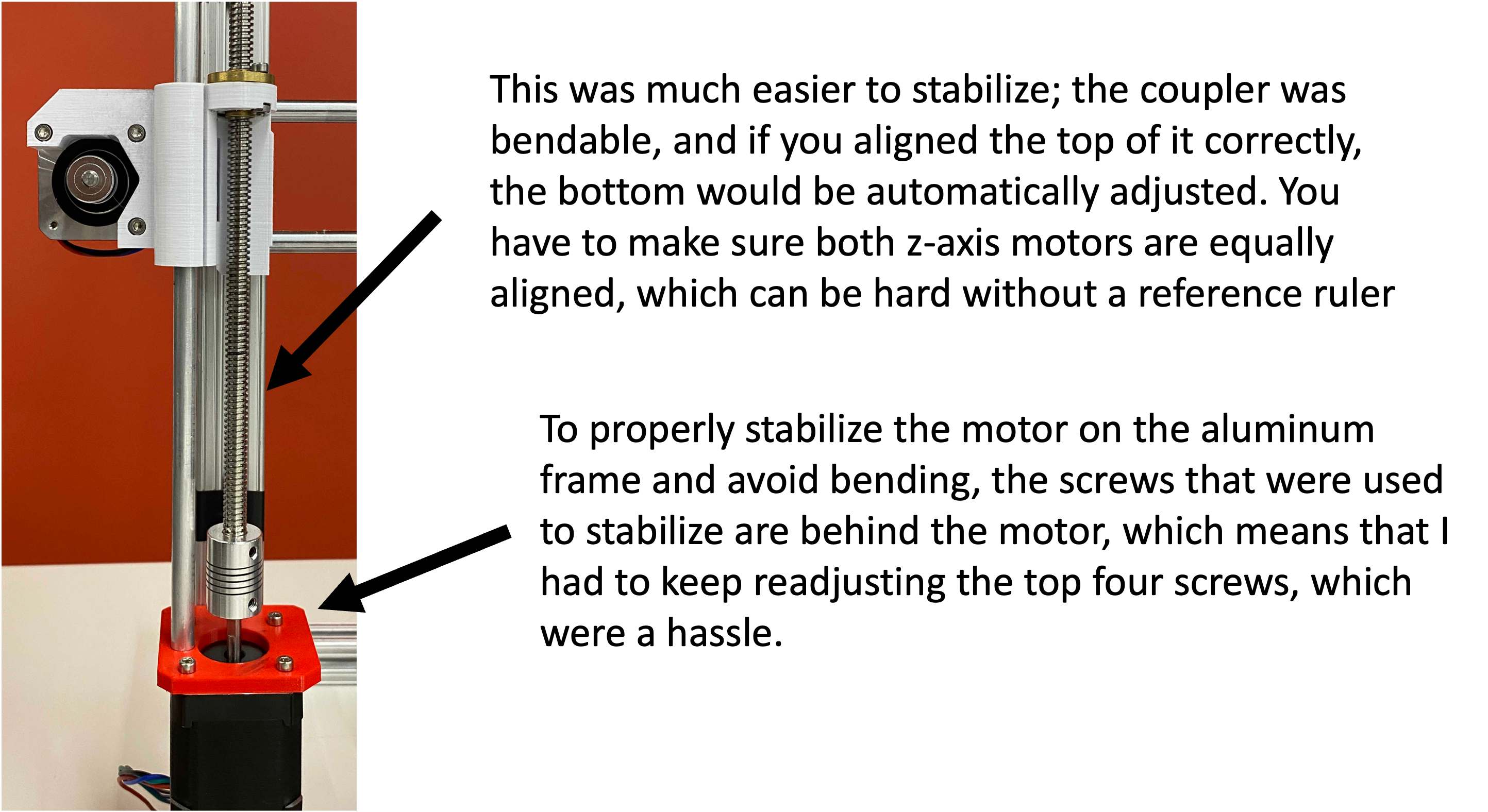
| 5mm to 8mm Shaft Coupler | McMaster-Carr | $15 |
| Timing Belt, 5M GT2 2mm Pitch 6mm Wide | Amazon, Eewolf | $11.99 |
| 30 Aluminum Profile Connection | McMaster-Carr | $7.00 |
| LEGO Bricks | LEGO inc. | $0.50 |
Summed up, the raw parts would have costed around $137, which includes savings from making our own DVR breakout PCBs. As a benchmark, good quality 3-axis machines cost upwards of $150 to $1000, with the Prusa printers going upwards of $700.
[6] What parts and systems were made?