Networking & Communications
I2C
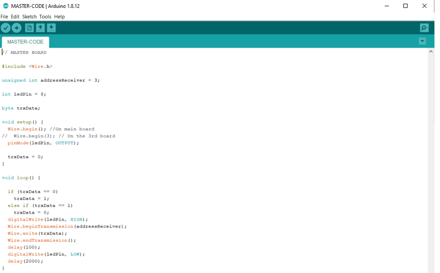
Knowing that I will be using multiple boards for my final project and that I prefer wired communication across multipe microprocessors, I decided to explore the I2C bus link.
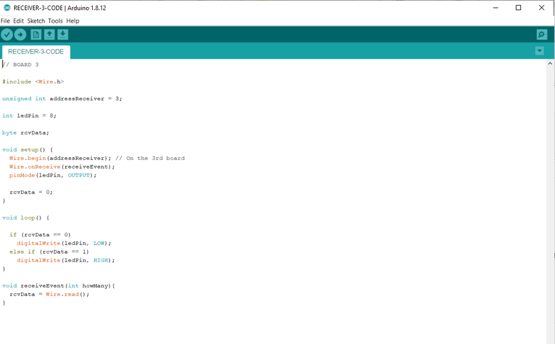
Working with two SAMD11C14A microprocessors on a single board, one will be the input [capacitive sensor] which I will be using for my final project. The other one would be an output, whcih is a servo motor.
I did not add a "master" microprocessor, instead the capacitive sensor processor is going to be that, since it is not receiving any data back, and would be one less connection, given that it was my first attempt.
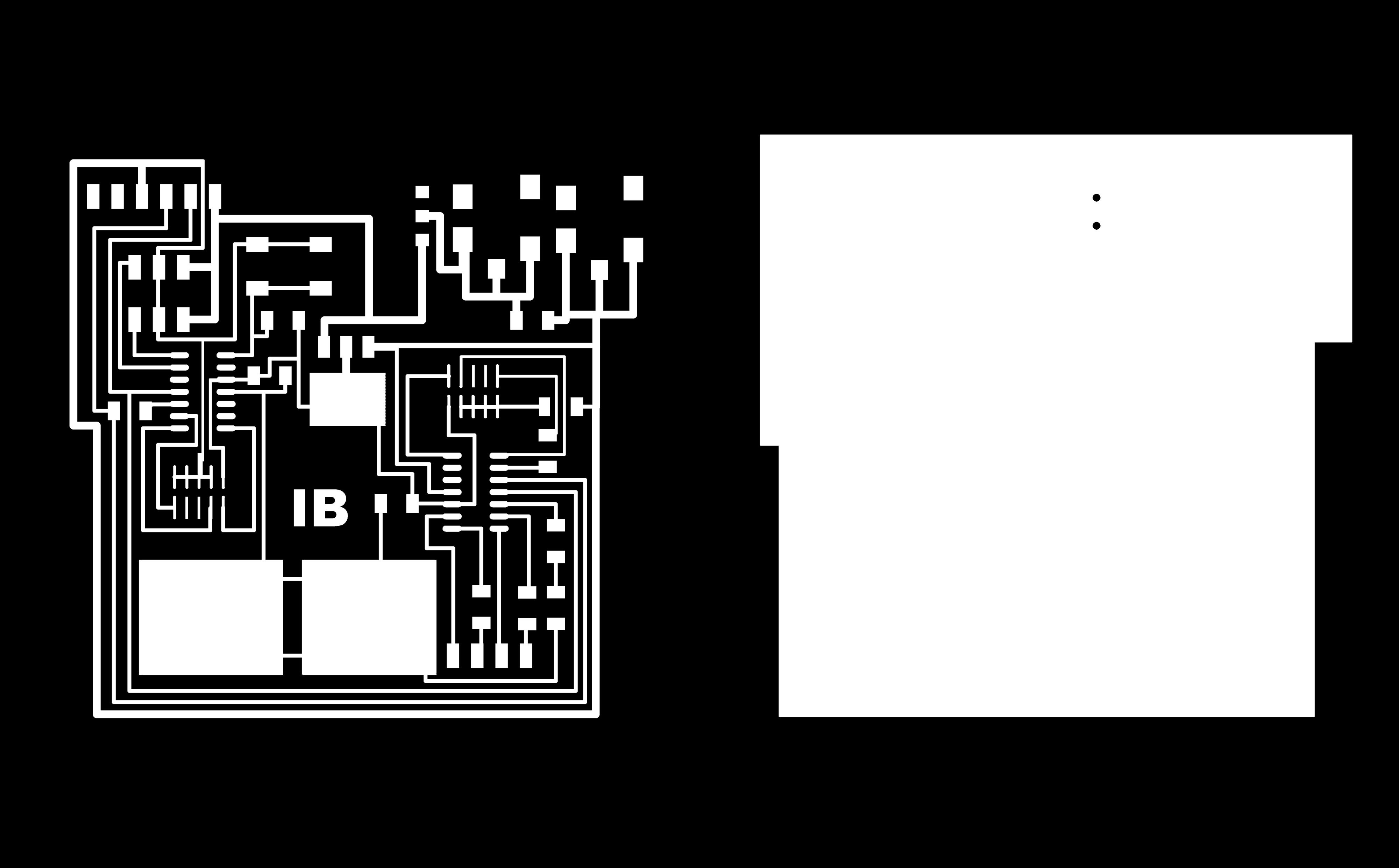
I began desiging the boards, integrating capacitive pads [the ground] on the board itself. I also integrated an external power supply connection to start testing that for my final project. The last change is that I excluded the USB,
in an attempt to upload code to the microprocessors via the programmer. This is essentially useful since I would be saving alot of memory space for not flashing a usb bootloader on the devices.
The board design.
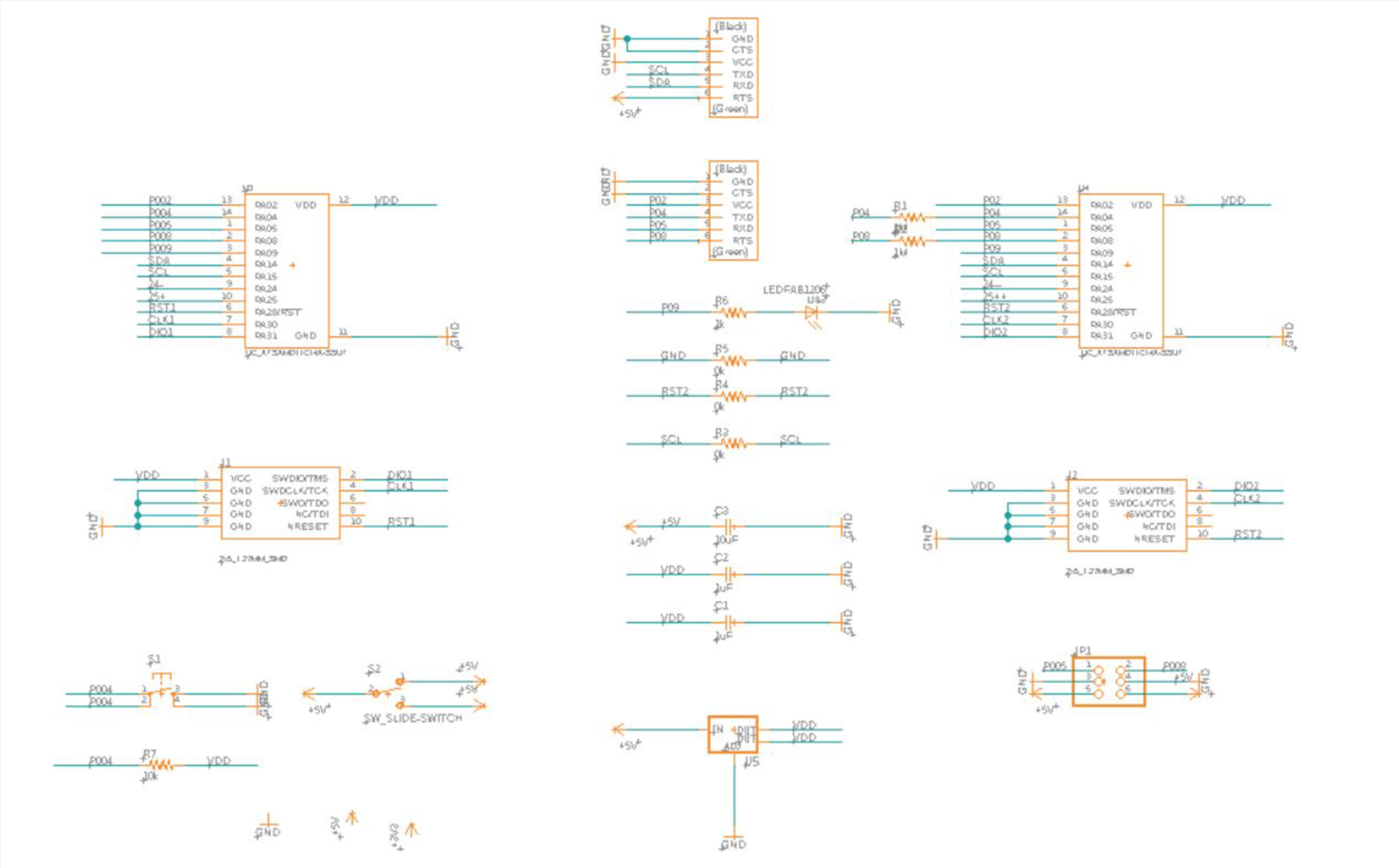
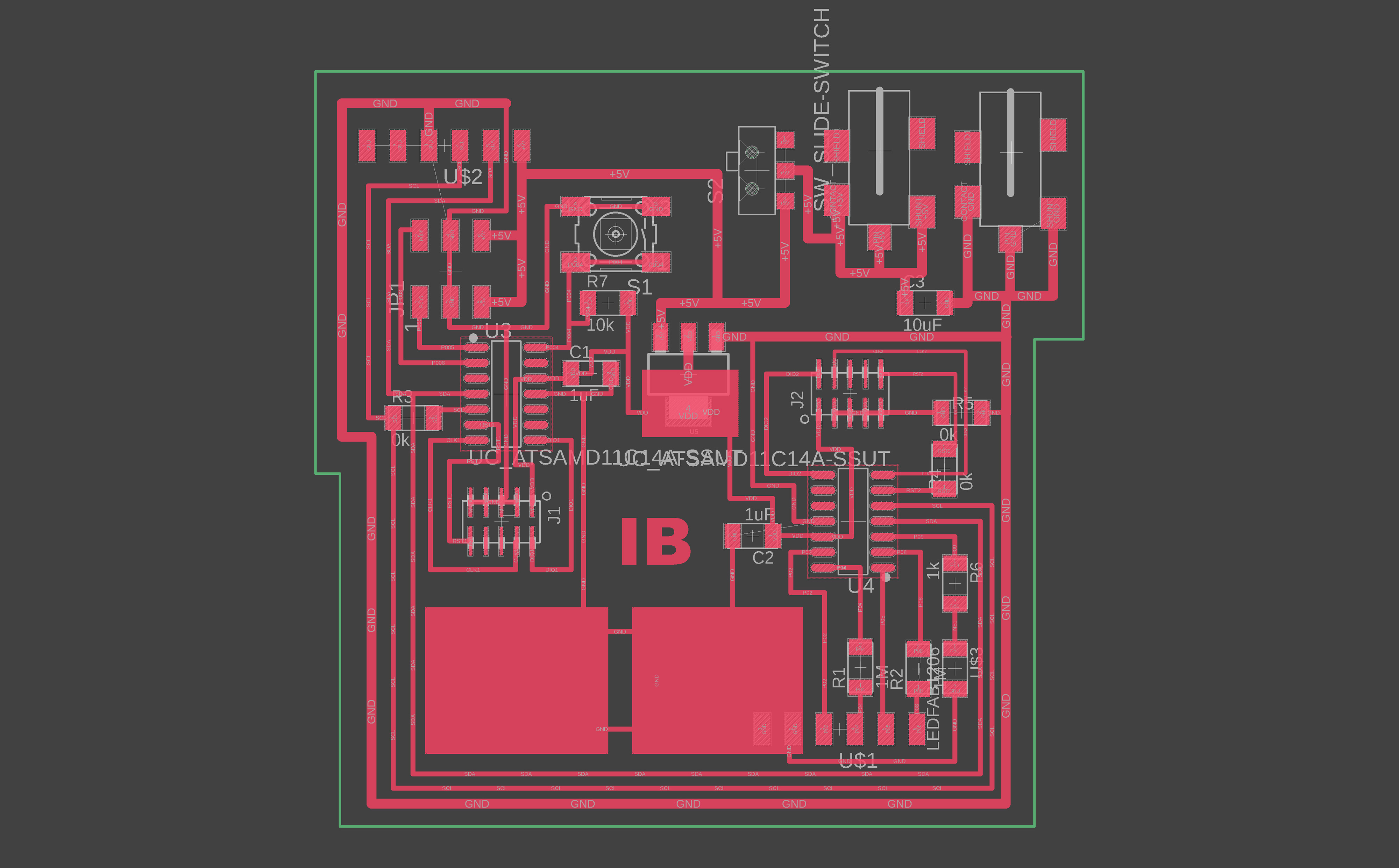
The board schematic.
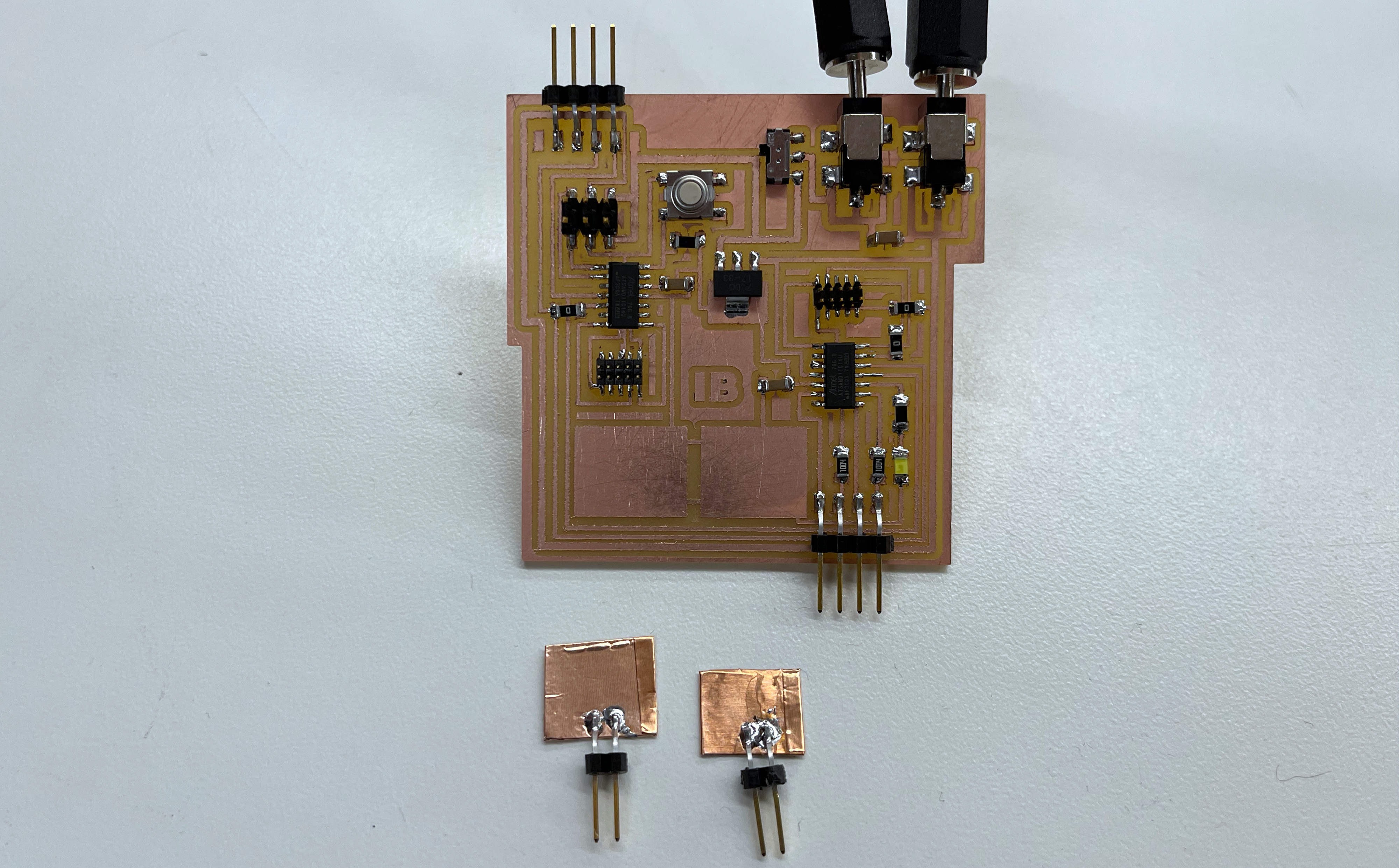
Milled and Stuffed board. Now wait for the errors [many of them].
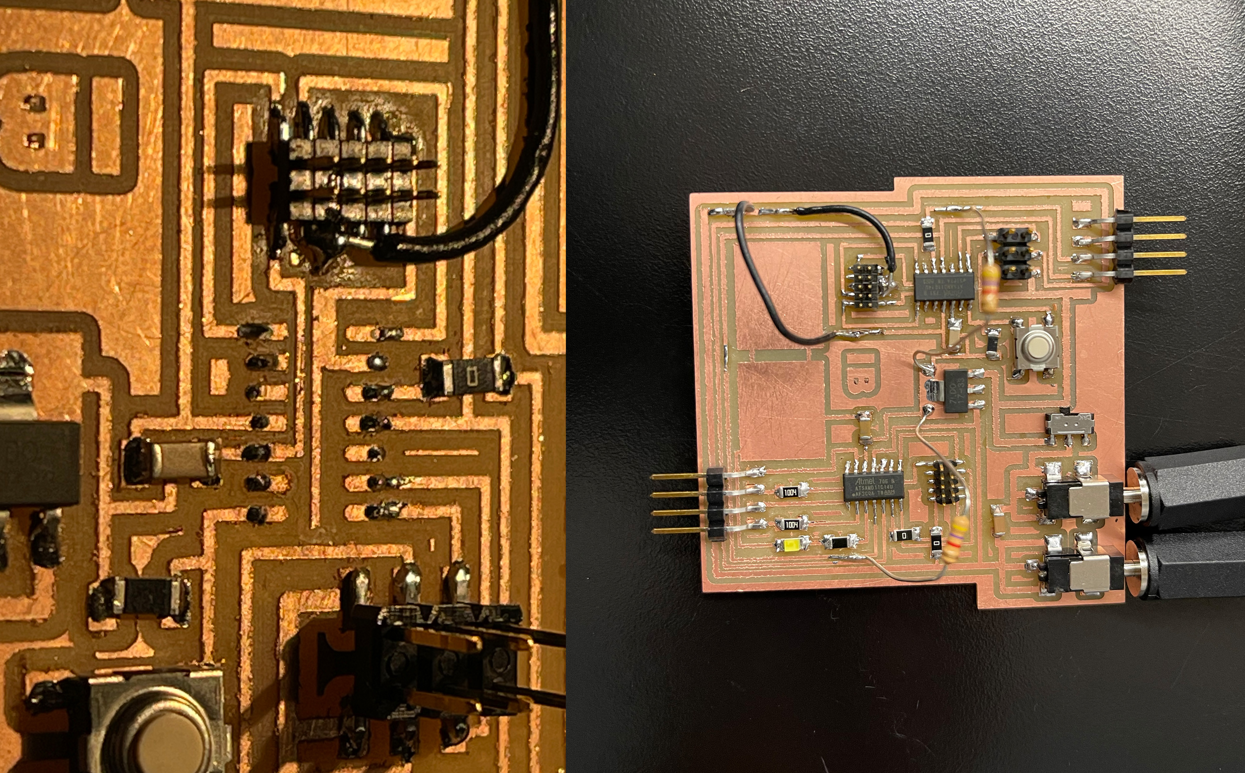
The first error is that my grounds were not fulling looping aournd where they should. I believe this was because of the capacitive plates. The design became stranger and I missed few connctions here and there, especially when ground terminates at a component.
In some cases, I should also connect it on the GND line if it needs to.
In total, four spots had to be jumped. At this moment I began loosing hope in my board. I usually dislike the baord once it had multiple jumper wires. Might as well re-mill it?
Another important one was the 4.9K pullup resistors between SDA and SCL lines. I was unaware at the begining that I needed those pullup resistors. After trial and error and looking it up with colleagues, we realized what was missing.
So I jumped between +3.3V and the SDA / SCL lines. I would admit that those resistors, although added as jumpers [which I dislike] were nice and gave the board a different character. Perhaps it was because of their color and texture.
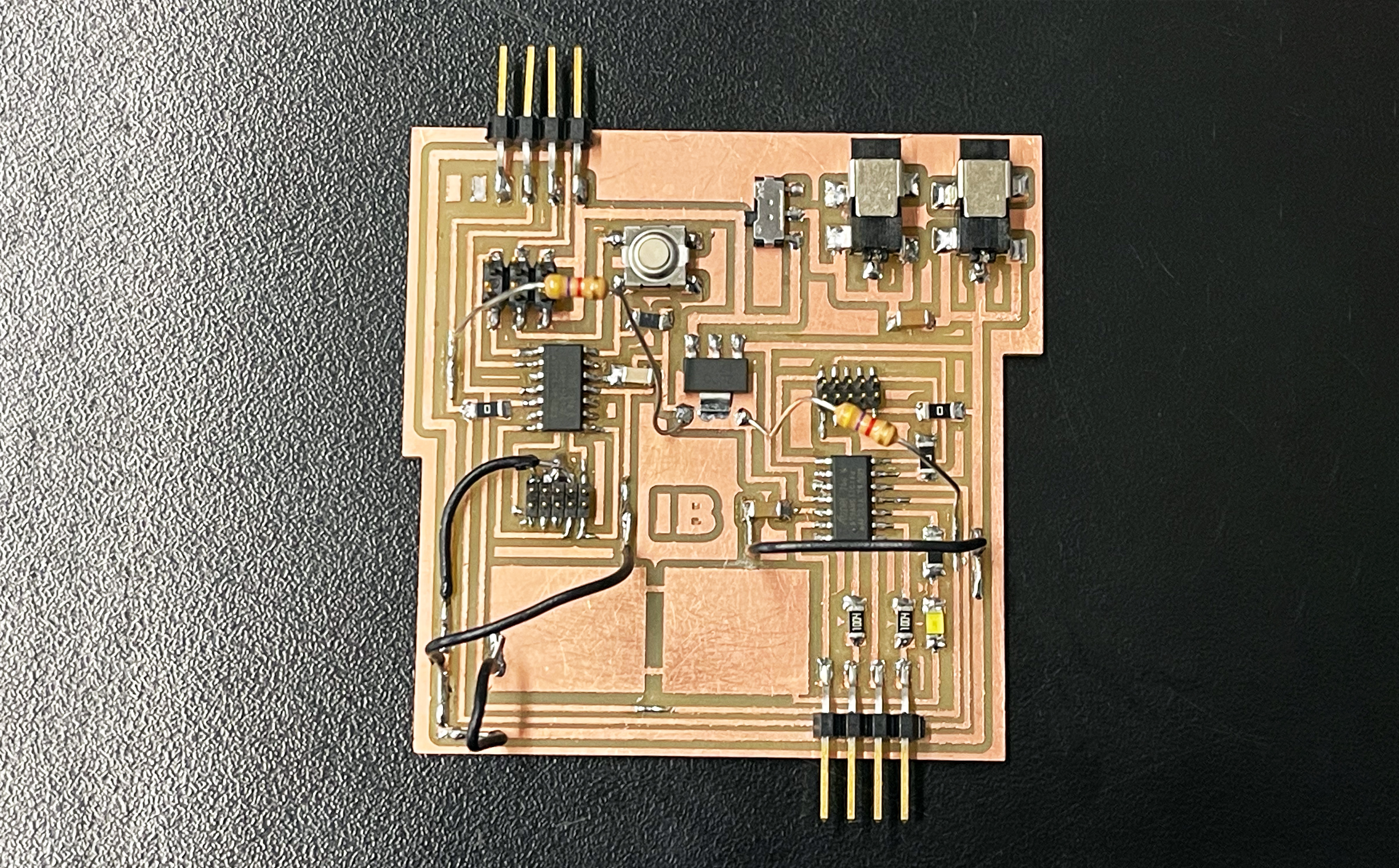
The boards finally programmed and were able to send a byte back and forth between both boards. The capacitive sensing had its challenges that I was testing, so that was aborted for the next few days, but it was useful to explore it and learn about it not few days before the final. I have another final project due on the 13th...