For this week, I decided to start implementing some of my final project's components. I began by looking at different robotic / gripping and movement mechanisms. I was struck by the high appreciation to the delta robots verses the old 6 axis robotic arms.
It seems like users are preffering it over the older for its high precision, easier control and lower maintenance requirements. Although I was very much convinced that it is the right tool for me to incorportate, I decided to continue looking at both options: The delta robot, and a 6-axis robotic arm.
Perhaps I could incorporate both and let them coordinate a task that can't be done by one? Let's see where I can get with this first.
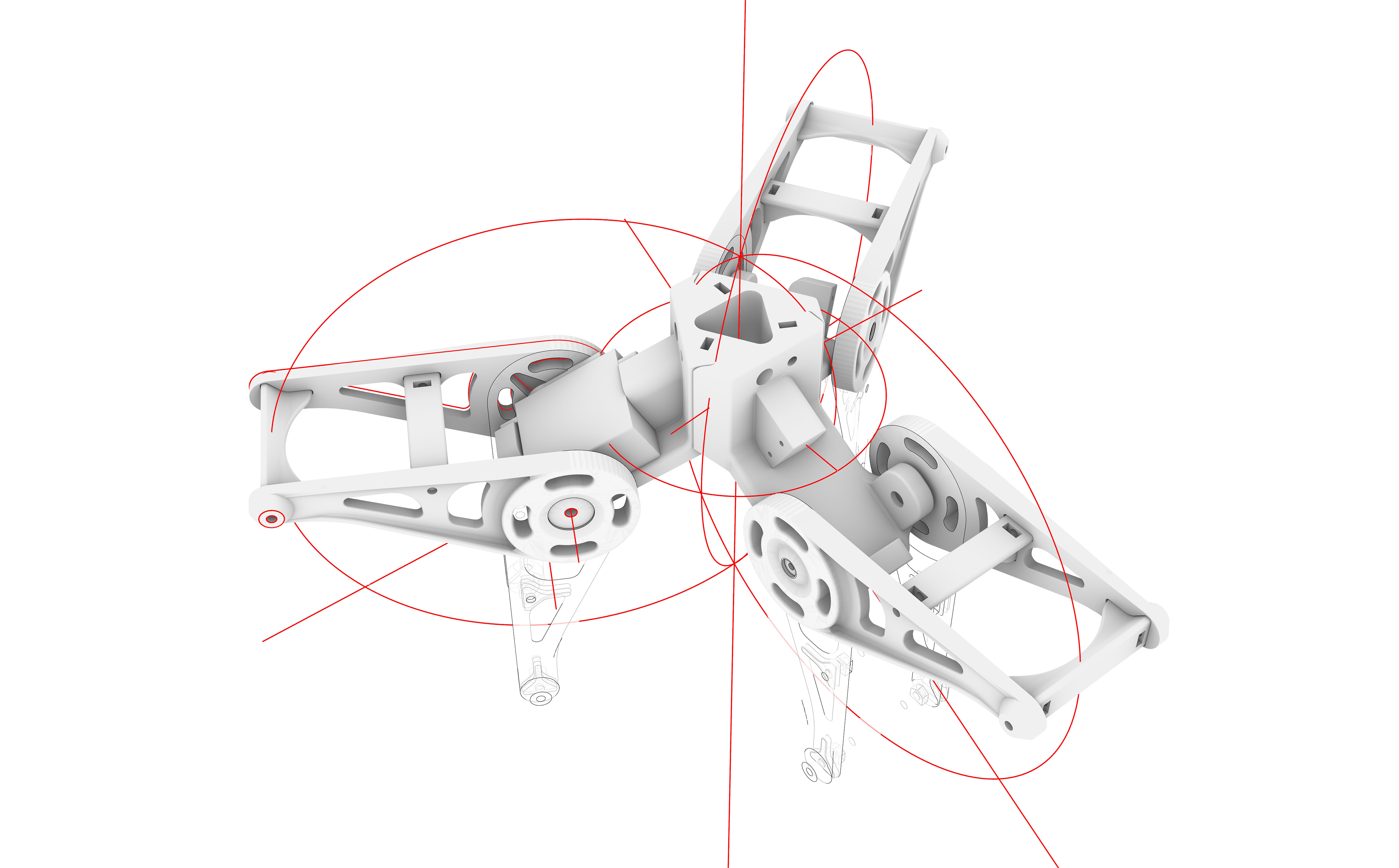
I surfed the web for exisiting models to understand the proportion of the delta robot, the required mechanical parts and electronic components. Of the good ones, was a model by eezy robots that had a decent amount of detail, clean geometry and easy to follow steps. I took the model and decided to edit it to fit my own needs.
In rhino, I build the main axis step by step following a 120 degrees points to get three arms. From there it became modular and I started working on one arm, puting the required parts, noting what screws are available and preparing files to print.
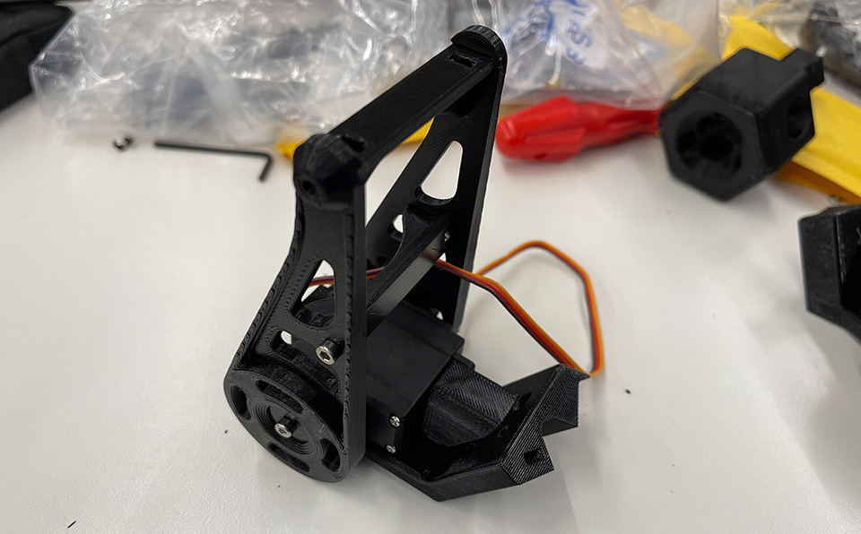
As you can see above, the arm rotates around a servo gear that is mounted on a 3d printed base. This base will eventually take in the wires and attach itself to the upper axis.
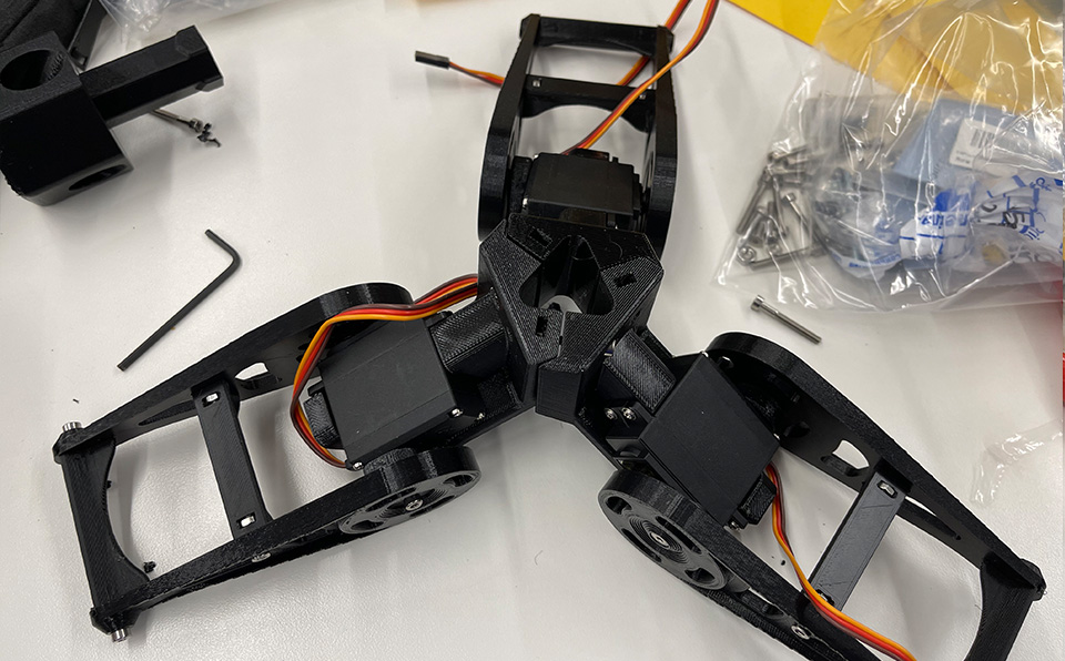
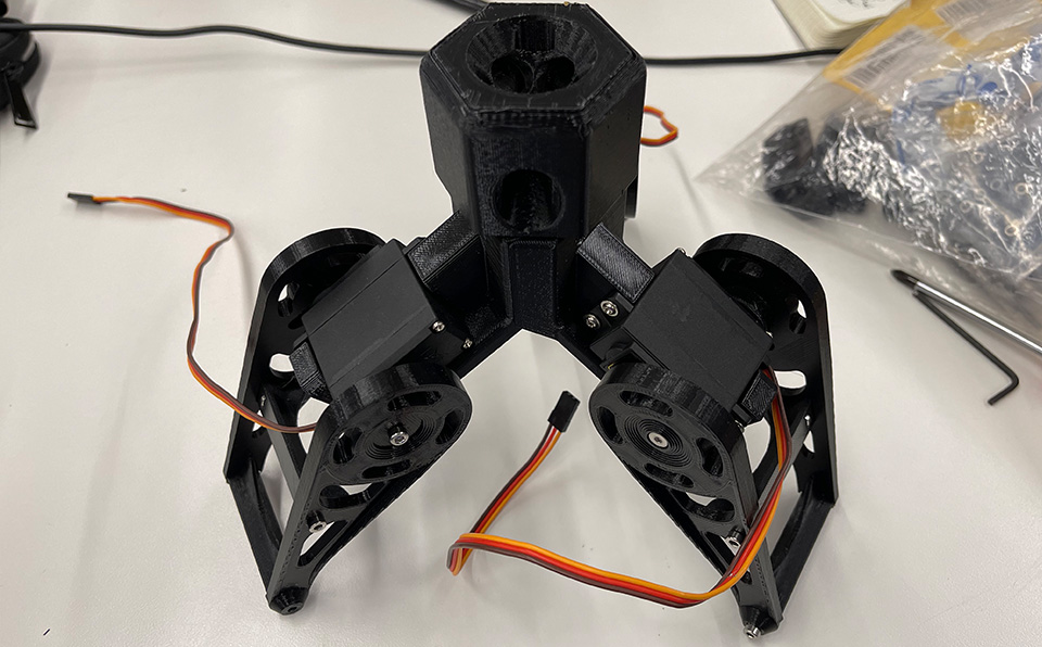
The three arms assembled for testing before printing.
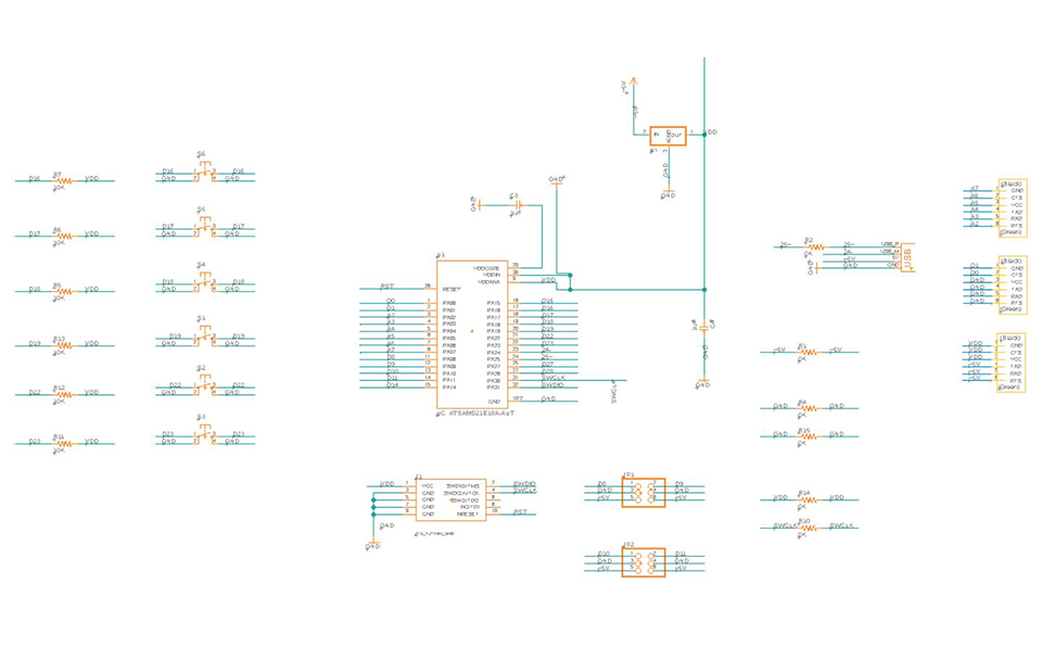
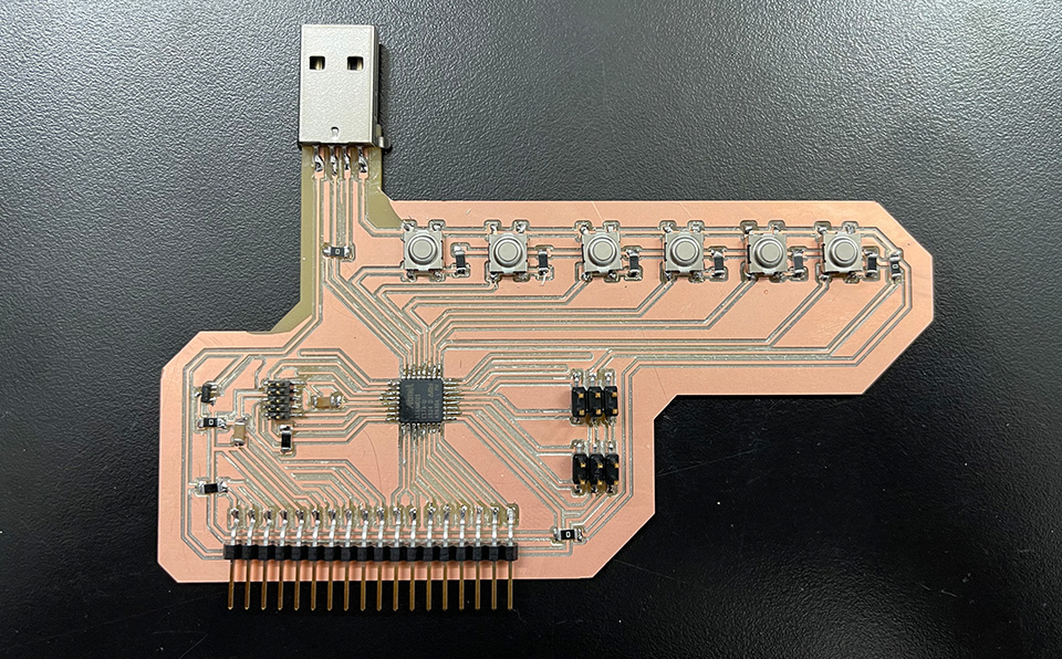
Then I proceeded with designing the board. I decided to use SAMD21E for it provides alot more pins than the SAMD11s. The idea is to be able to control each of the three servos with 2 buttons. One that moves it clockwise, and another that does anti-clockwise movement. The board could take in 4 servos, assuming one could go for the gripper servo.
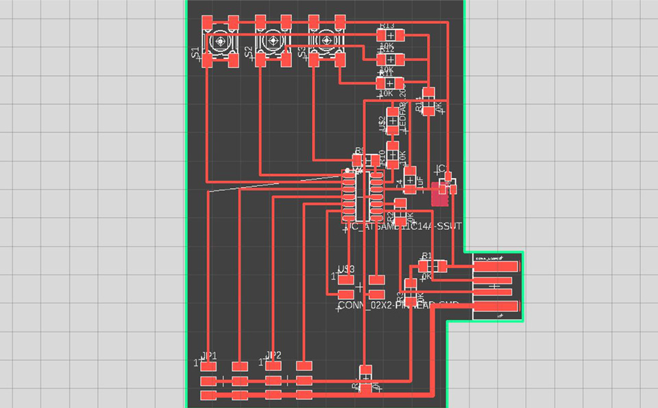
Above is the schematic. I looked at previous student work who've used the SAMD21E and Lingdong from our class who had used it in embedded programming week. Those were very helpful given that the SAMD21 had few power pins that were different from the SAMD11. File to download is at the end of the page.
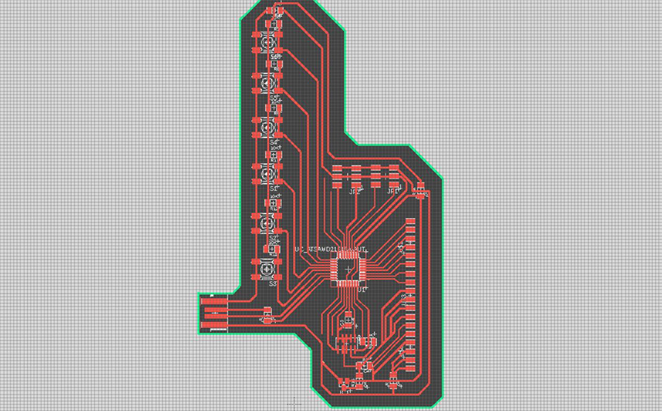
The board design in fusion 360. Files to download at the end of the page.
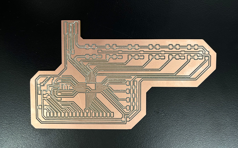
The milling process went somewhat smooth, given that the traces for the SAMD21E are much thinner compared to the 11. It turned out well, but could have been better with a newer 1/64" milling bit.
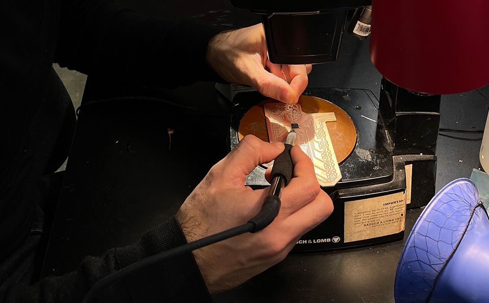
the board was stuffed and ready to be programmed with edbg. It flashed a bootloader and began writing my simple arduino code [available below for download]. The board acted strange, the servo moved once, before it stopped moving and the board is no longer registered as a usb.. Something went terribly wrong! I assumed with current which fried the board.
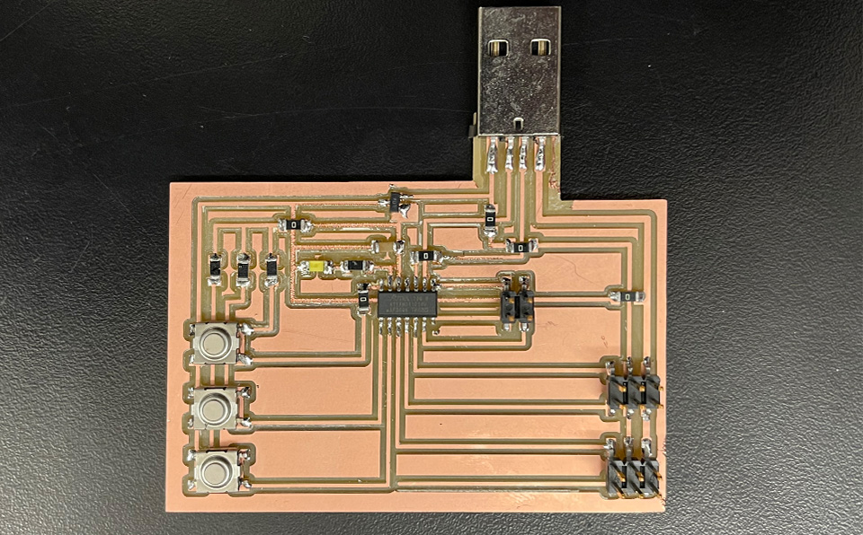
I did not have much time, so I decided to simplify the board and revert back to the D11C.
I designed, milled and stuffed the new board hoping that it would work. Again facing the same issue I did with the 21. It was already getting late so I decided to end the day with unhappy, unexpected failure in hope that I can figure out what the problem was after class.
Here I began assembling one of the three arms of the delta robot. I choose black pla (hopefully I don't regret my choice later on when putting the machine together), imagining an almost all black machine with some metalics.
The three arms coming together around the node.
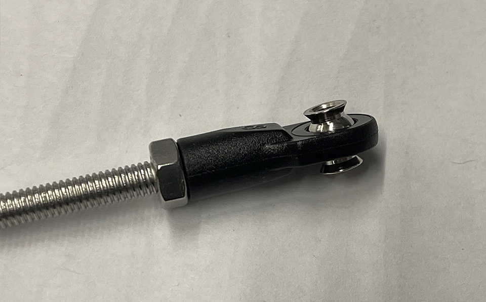
wip - the lower part of the arms which connects them to the gripper base