Final Project
Easy Make Oven
Pitch:
Find yourself longingly looking at 3D prints and wishing they were pancakes? Tired of eating the same round or rectangular cake shape every year? Well fret no more because EZ-Make Oven uses an edible filament to create edible 3D masterpieces!
Description
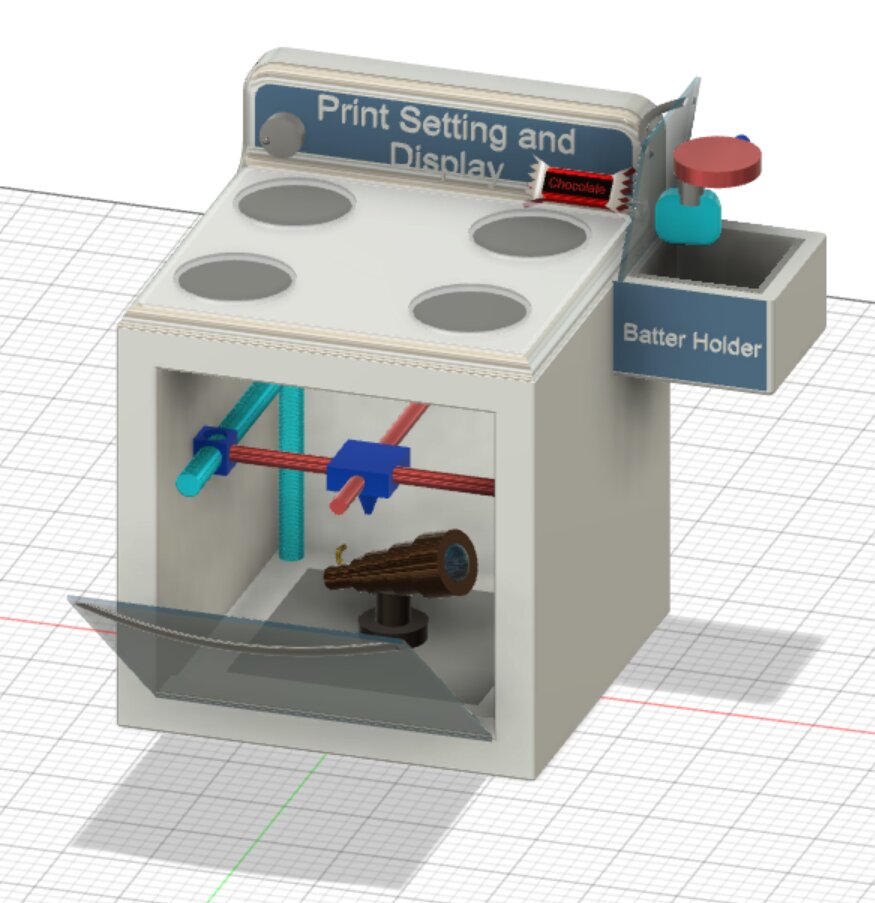
I love making pancakes with my little siblings, but even though Apple keeps on coming up with upgrades pancakes haven’t been innovated on in a while. As such I decided to simply combine pancakes with something else I really love: 3D printers. How cool would it be to eat a syrup-covered replica of the Eiffel tower? I know I'm not alone in finding that prospect intriguing. My project idea is to bring baked goods into the third dimension as an additive practice rather than a subtractive one. I was mainly thinking pancakes (because I’m biased and love pancakes), but it can't be that hard to extrapolate and change based on batter. As a child I had an EZ-bake Oven, which is a device that cooks batter using a 100 Watt lightbulb, my product would get a similar name of EZ-Make Oven for its ability to both cook and make complex edible shapes whilst maintaining the shape of a traditional oven. FDM printers work by taking a solid material, expending energy to liquefy it, and allowing it to cool back to a solid. SLA printers work by curing a specific layer of liquid resin in a tank with a laser and building on the layers. SLS printers use a powdered "filament" and fuse the powder together with lasers. My proposed project would start with a liquid filament (like SLA) but have to put down layers of it (like SLS and FDM) it would also have to cook/cure the layers (like SLA and SLS) without burning previous layers. The “bed”/ bottom-layer-curing would likely be created like a griddle, the other layers will be cured using a heat gun, and sending jobs to the printer will probably involve a crude slicer that gets really low-resolution slices of the image and tells the extruder/heat gun how to move. My two current ideas include a one extruder version and two extruder version. For the one extruder, I won’t have to completely remake the slicer but will have to make the machine double-pass each layer, essentially taking normally produced g-code (from somewhere like Cura or Prusaslicer) and telling it to repeat its previous move, once for laying down batter and once for cooking it. The two extruder version would involve using already-built software to slice the file for two extruders, one for cooking and one for laying down the batter. I think this project sounds really fun and it will be interesting to taste a cake/brownie or pancake that is cooked evenly throughout.
Background
I am a manus makerspace mentor, course 2A-6, and avid maker. I pretty much live at metropolis and know how to use most of the machines there and in the deep. I love CADing (have already CADded a model for the project) and have recently learned PCB design and manufacturing. I was also part of the team that won 3rd place at MakeMIT last year
Reality
Before considering the mechanical/electrical implications of this project and all the little things I'll
need to get just right I'd like to say that I quite love the idea of a 3D printing oven, but in
practice, it seems really difficult… Far too difficult for a final project with such a close due date…
so I’ll simplify. Simplifying the dimensions is really easy to upgrade upon at a later point whilst
making my life much easier at the moment, so I’ll build a 2D printer instead of a 3D one. I’ll also you
pancake presets or g-code the machine comes preloaded with to constrain the shapes that are being made,
this will:
Allow me to make the shapes pretty refined
Not have to worry about compatibility with slicers
Restrict people to only the shapes I deem worthy enough
The 4 shapes I have chosen have been my go-tos throughout the semester: turtles, dolphins, triangles, and narwhals. Fear, not A 2D shape-restricted printer is not my end goal and there are ways around this limitation. Pancakes are usually served stacked and caked with butter and syrup. I will take advantage of this fact to create 1-7 individual pancakes that can be stacked during post-processing to create the perfect 3D shape. Now that’s all fine and well but what about shape restrictions? If I have time or more accurately if the TAs have time to help me figure it out, I’ll try to find a way to simply augment the g-code files from a slicer and process from there. The path function from mods seems pretty handy for doing this or maybe something from Ultimaker Cura slicer. Either way, the freedom of choice will be considered at an appropriate time.
Real Reality
Plans vs Outcome
I’ll have to purchase a lot of the non-negotiable parts, but I’ve already begun working on a temperature sensor for the bed. Homemade 3D printers are becoming more common and there are kits where you can just assemble your own so all I have to do is take the basic parts of a printer and recreate/repurpose them for my needs.
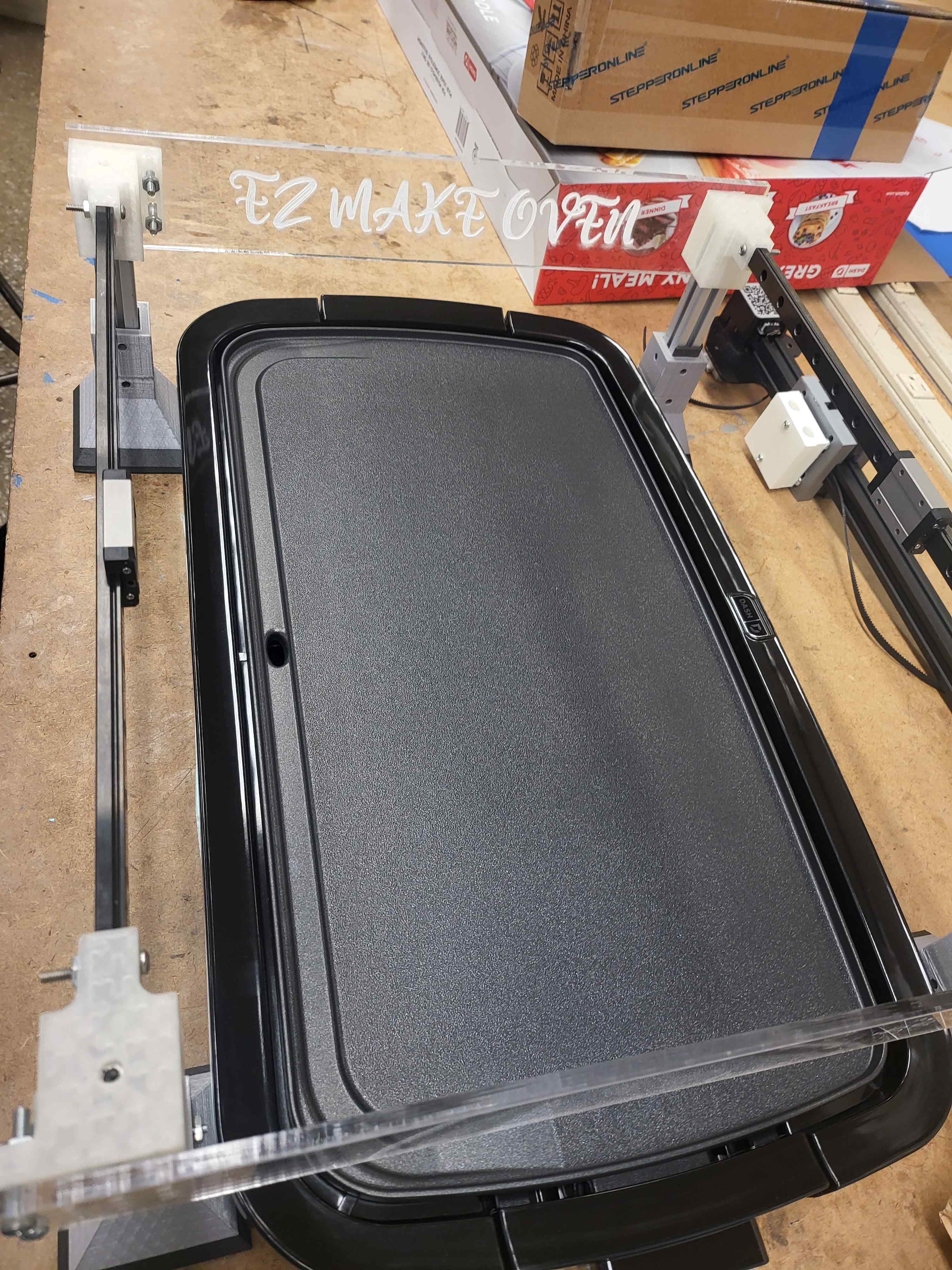
The BED
I plan to purchase a griddle for my bed this is a safe way to create the heat that I need. I want the bed to be moving in the Y-axis as well so I’ll mount it on linear rails driven by…
I found an amzingly cute griddle online IT'S BLUE, it's giant, but it's blue, and so I scaled up my entire model to match this griddle size, suce a large and heavy and hot griddle could not feasibly be moved, plus it's dangerous to expand the burn zone especially for those of us who are more accident prone.
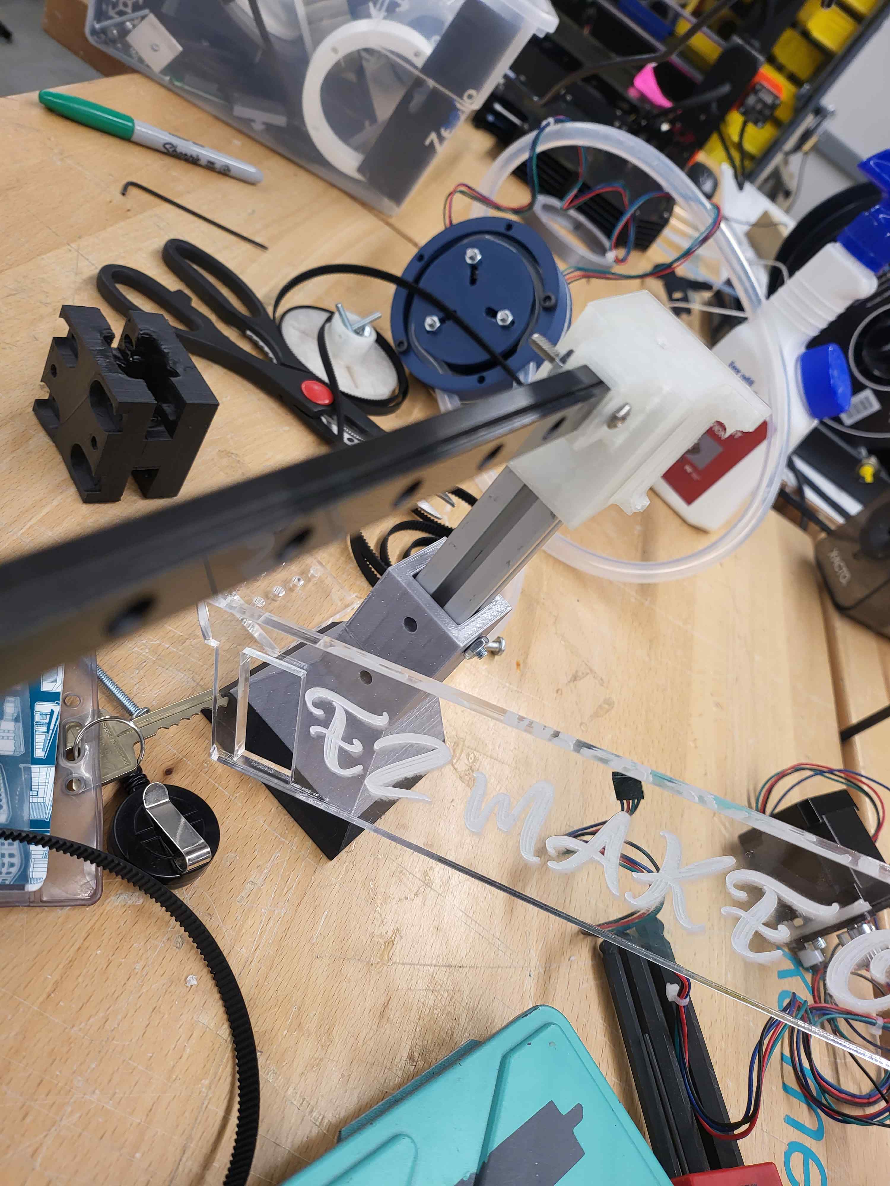
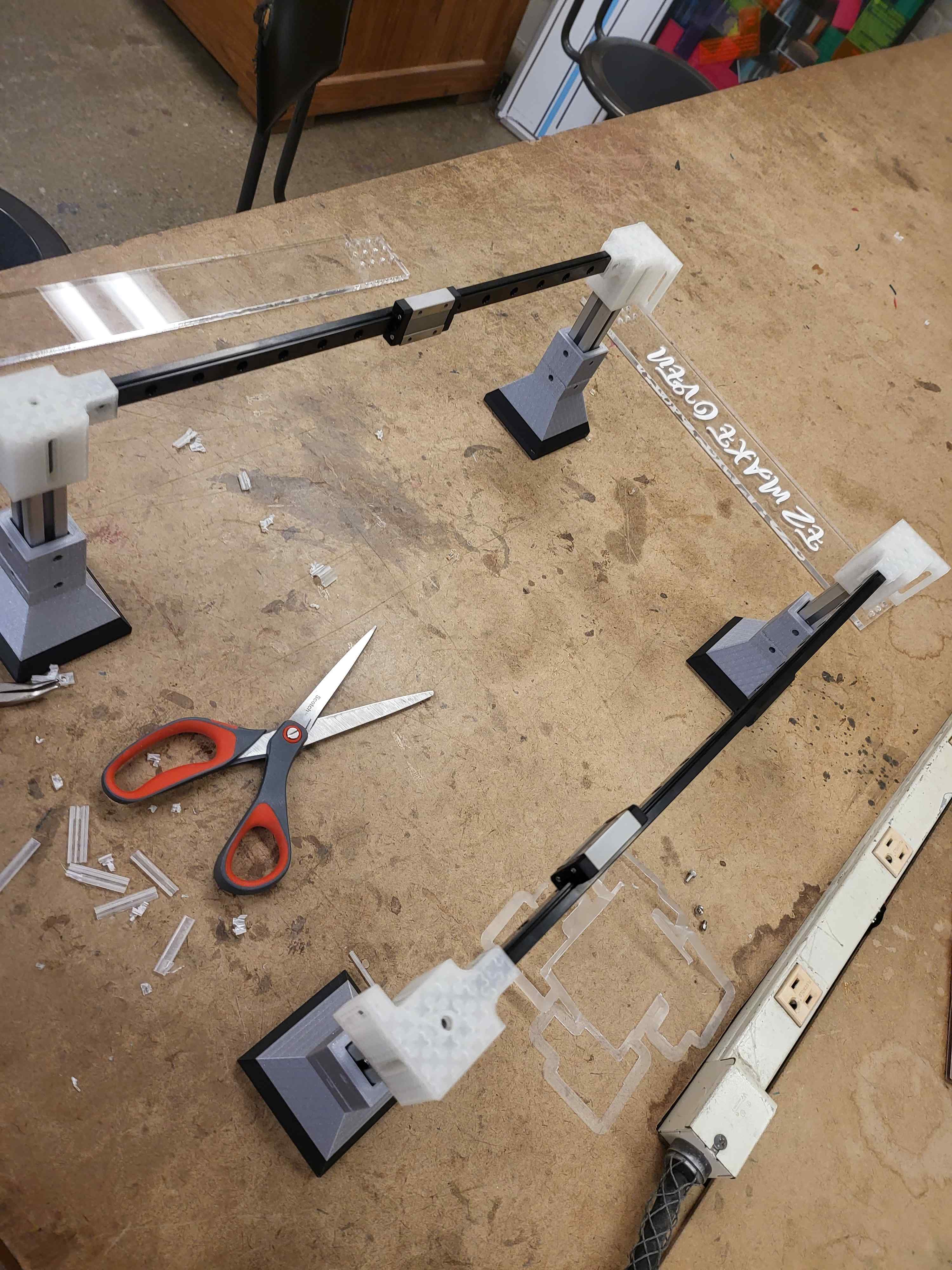
I kept talking about how much I loved cadding this entire semester, but I have mainly done just for show cool looking cads that didn't have to fit parts and such things, there are so many tools that I have yet to explore such as importing parts to get all of my dimensioning right. So that's what I did I cadded the entire gantry myself and figured out an implementaion of it, things weren't perfect but it worked and I'll go more into more detail about this later.
The Motors
Not sure why these needed their own section I just thought it would be more dramatic. I’ll purchase some high-quality stepper motors to control the head and bed, I may or may not have time to at least set the frame up to hold 3.
The frame
I think I’ll stick to a mainly metal but partially 3D printed frame, just because I’d love to learn/work with welding and the griddle will be very hot and 3D prints melt, and I eventually want to cook higher layers with a heat gun meaning even more wildly firing heat. Which brings me to the next part…
The Chill
Because chill sounded cooler than just saying that I’ll need fans to keep it from overheating.
The Axiis
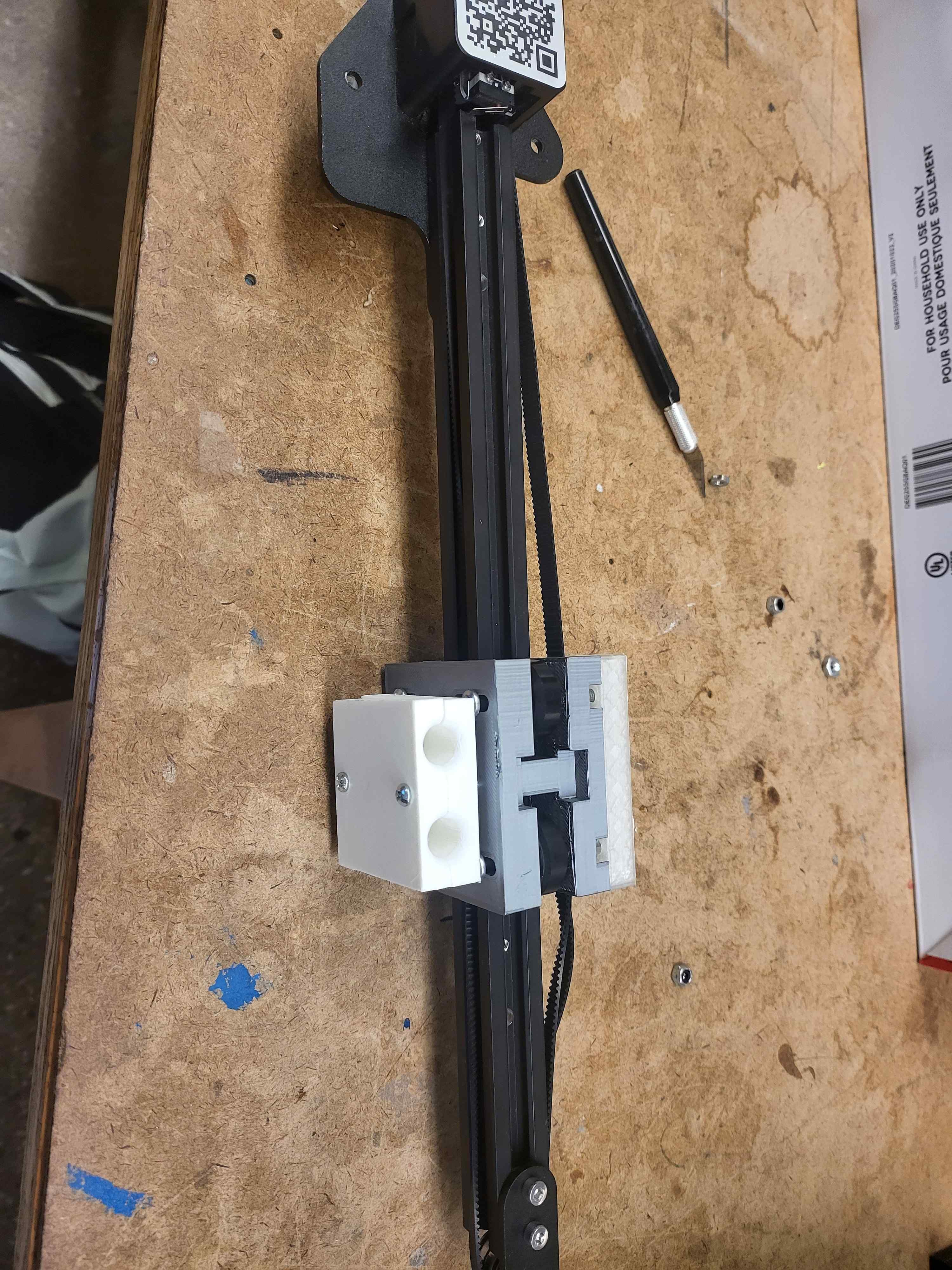
I’m 90% sure that that’s the plural of axis and I’ll need at least two, probably in the form of purchased linear slide rails. I could try to make my own linear motion kit and I’ll keep an ear out during machine-building week. This is my main goal to apply what I've learned in this class and my meche classes to create a working gantry.
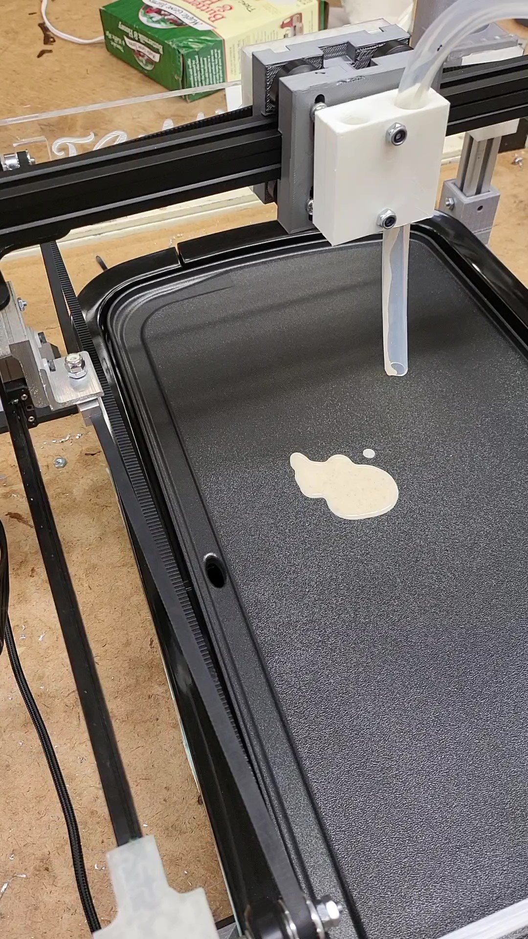
The Extruder
I will need a rather thick extruder head that is fairly heat-resistant as well and it has to be easily detachable for cleanups and refilling. I will load a giant squeeze bottle up with batter and it will need to be pushed through the head, I’ll probably also want a way to clean it up.
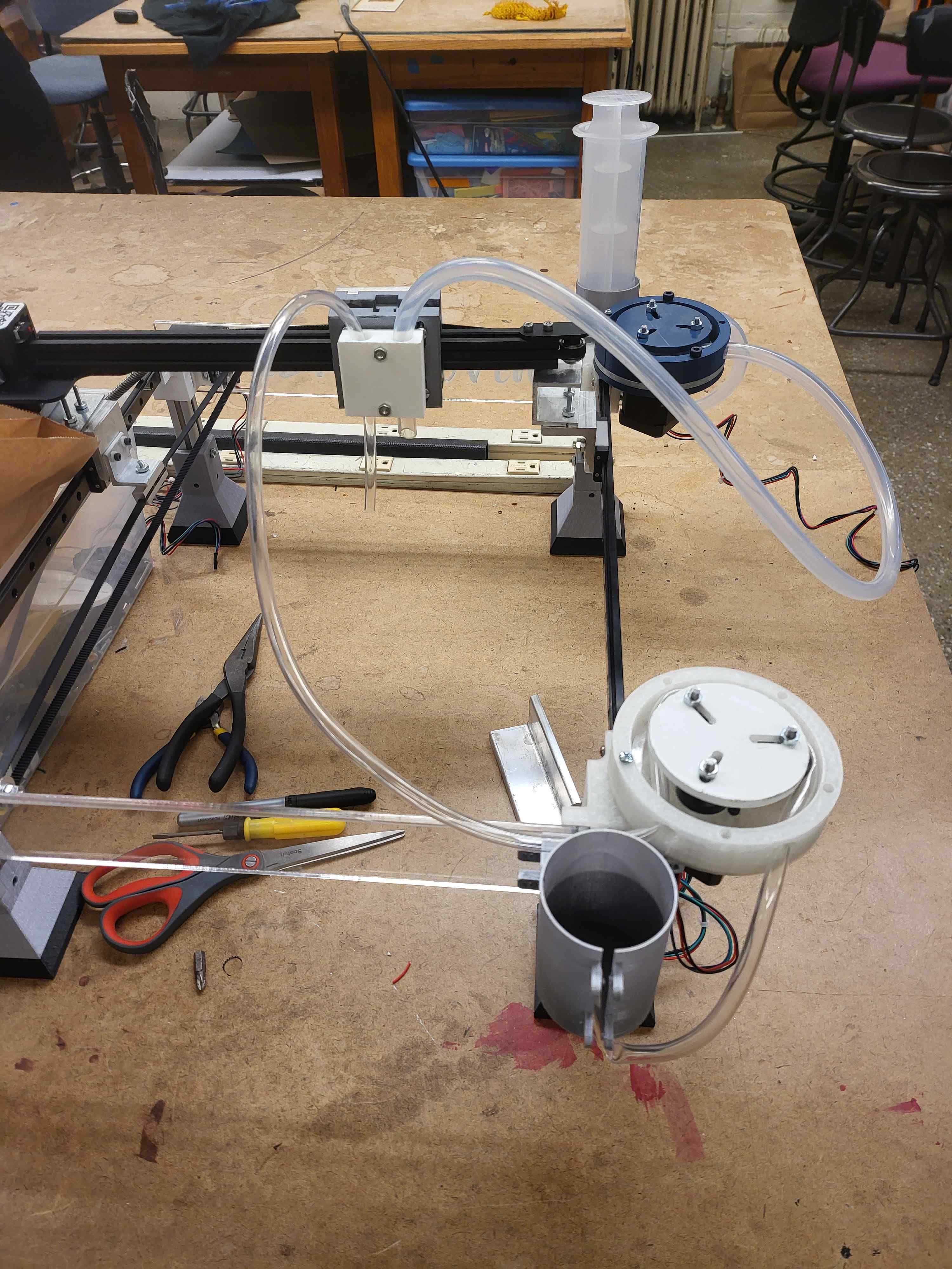
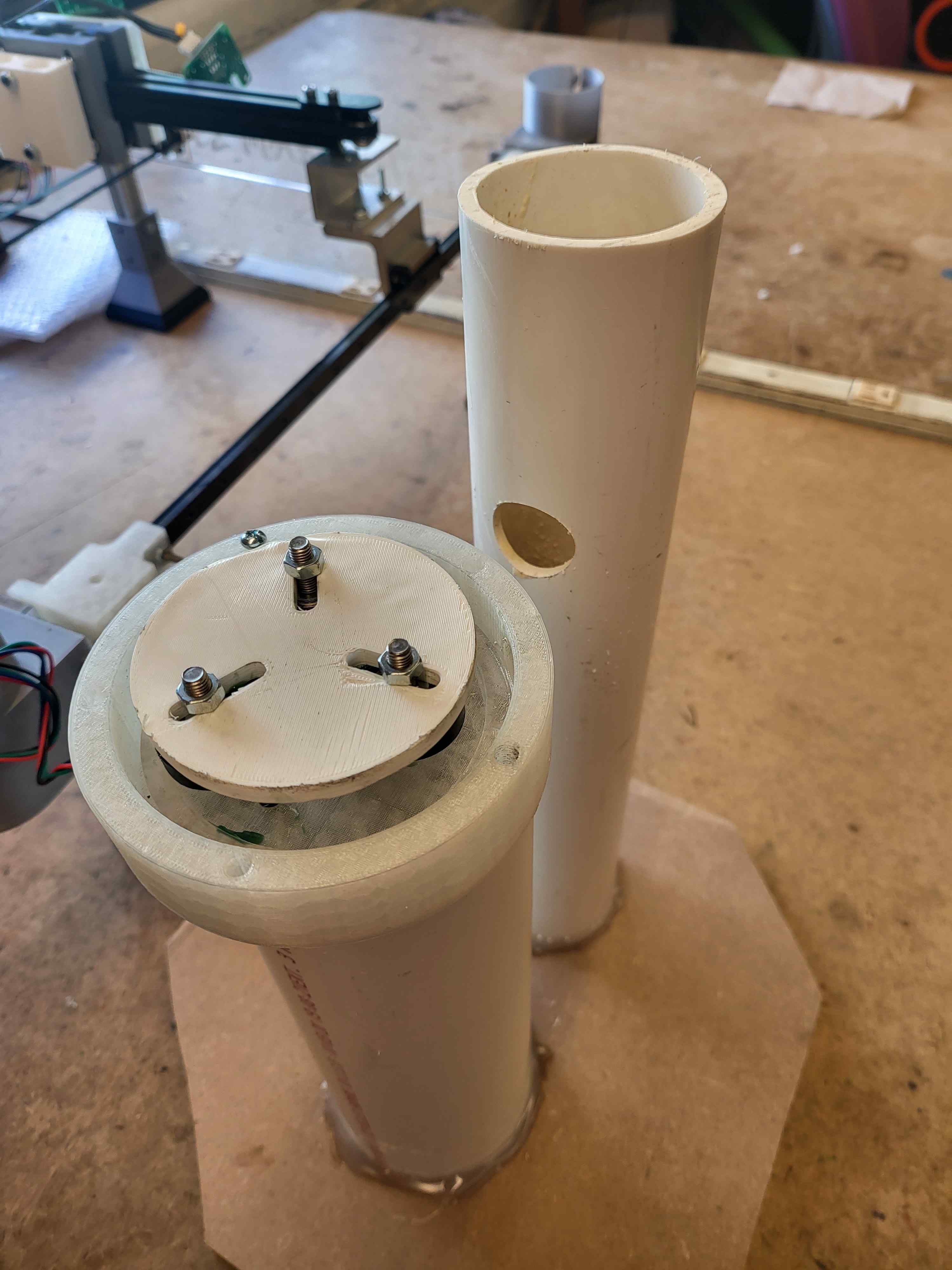
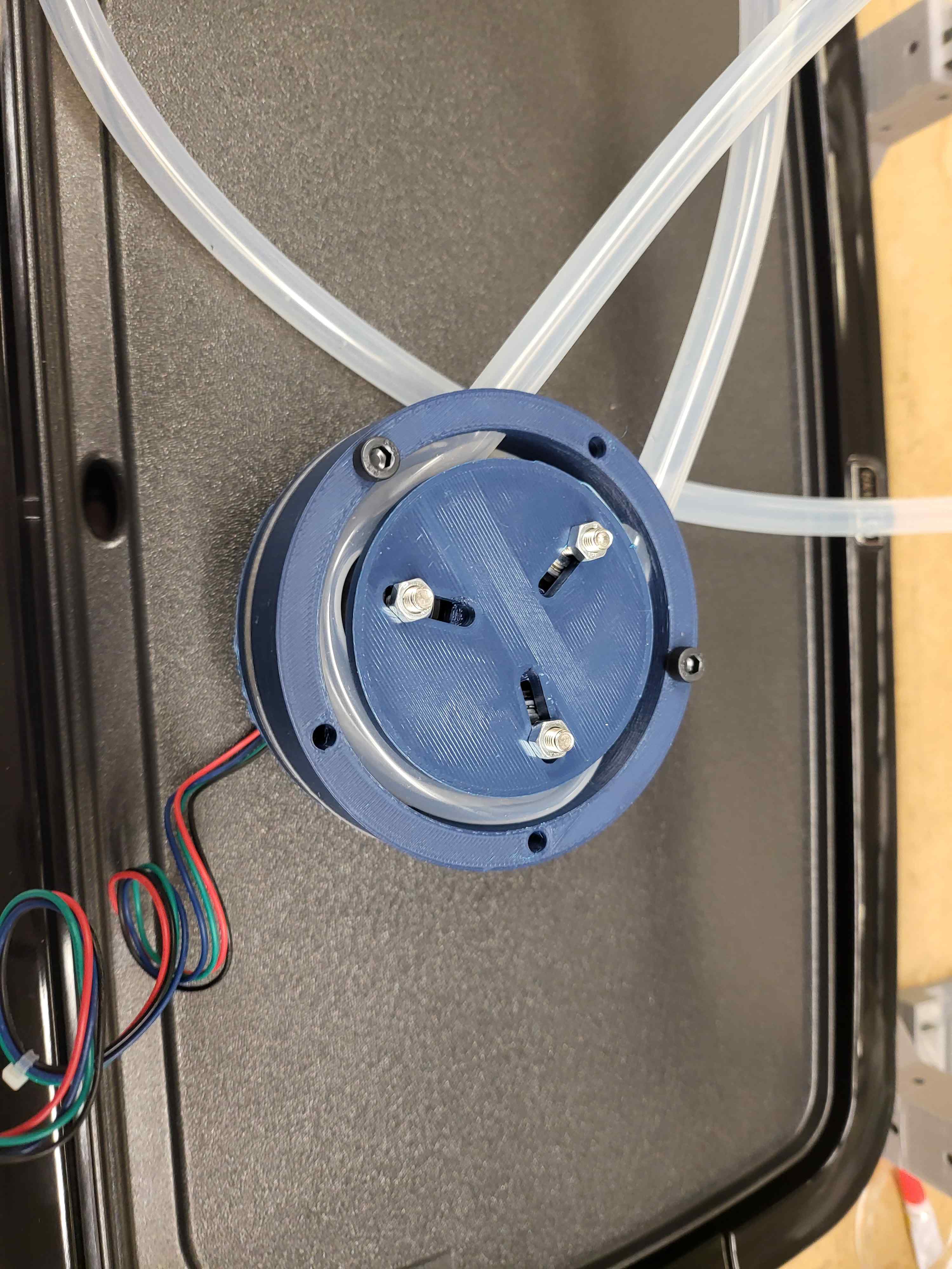
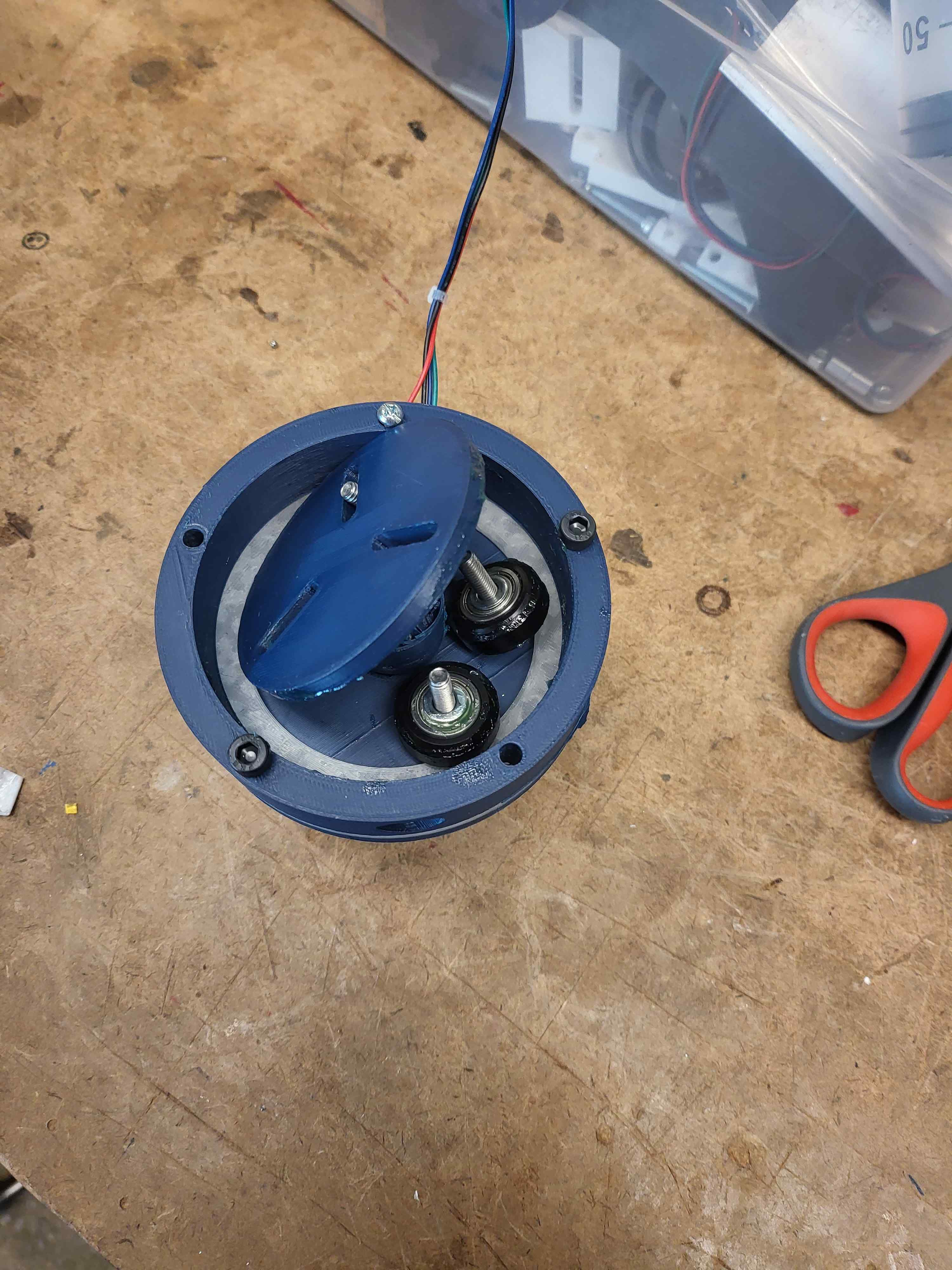
The Pump
I’ll have to find a way to “extrude the filament” or push the batter, I’ve seen both pumps and mechanical rigs that push it out, I’m leaning in favor of pumps but I am saying that far removed from the process and I love falling back on mechanical systems when electric ones inevitably fail me.
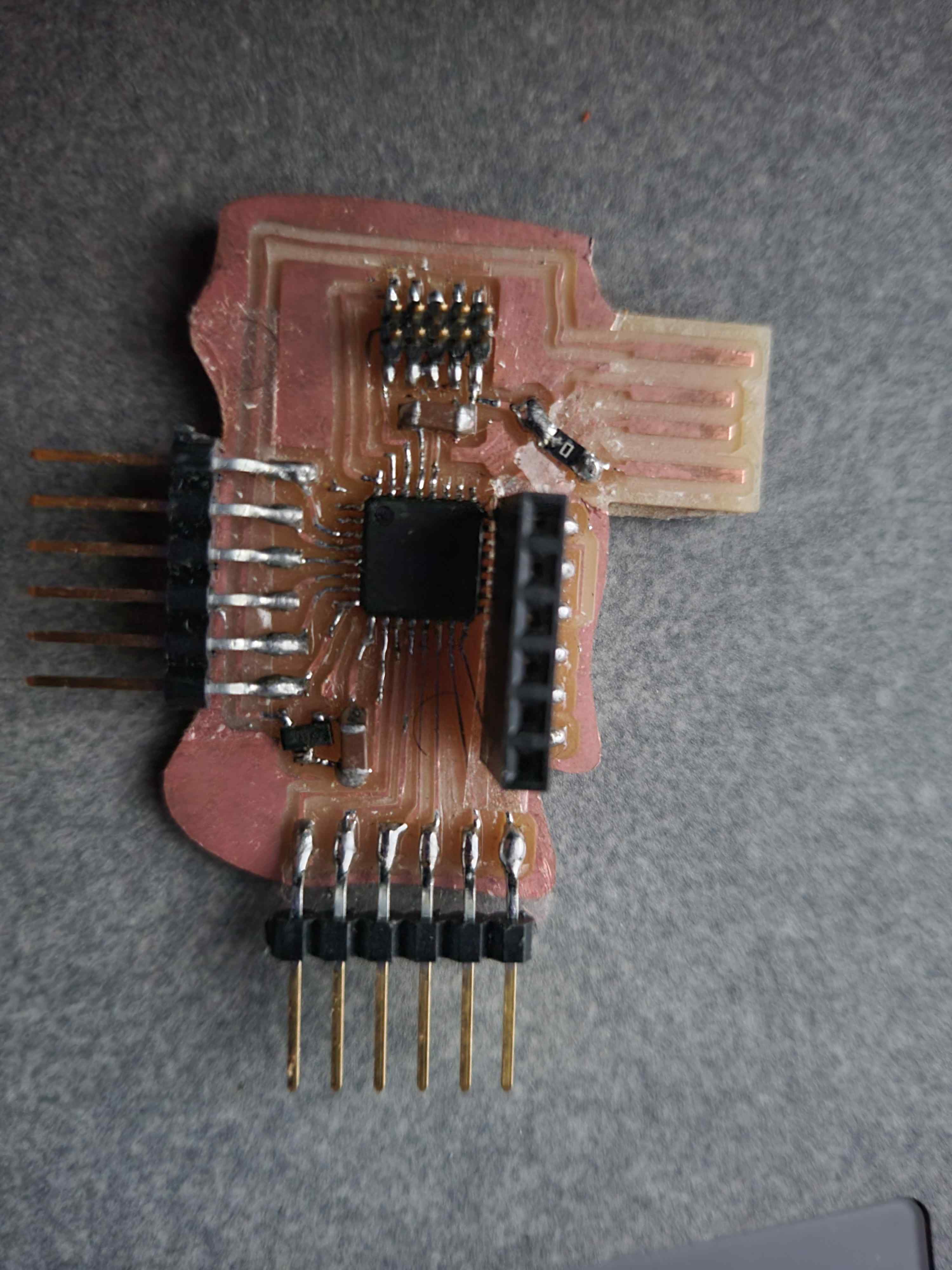
The Controller Board
This will be the crown jewel of my experience in this class and inevitably the hardest part of the assignment, I will need a board capable of driving 3 stepper motors, 2 fans, a pump, an OLED screen, a rotary switch or if that’s too hard several cute molded buttons. I will probably use a SamD21 because it’ll need a lot of processing power and I should make a breakout board for it to make all the components I need easily accessible. I will also make a temp sensor to check and adjust the temperature.
Change of Plans
THIS IS ME FROM THE FUTURE: so we just did output devices and the whole build a 3d printer control board thing is not happening, but I will build motor controllers to attach to the board. Also the machine in general is a lot of work so by using a peristaltic pump to directly move batter, I might get away with a bit more than I previously thought. Some changes for my sanity and that of future generations who will look back in shame at my failure: Really rough shapes if shapes at all, pumped directly with liquid pump thingy, simplify more if needed after talking with instructors.
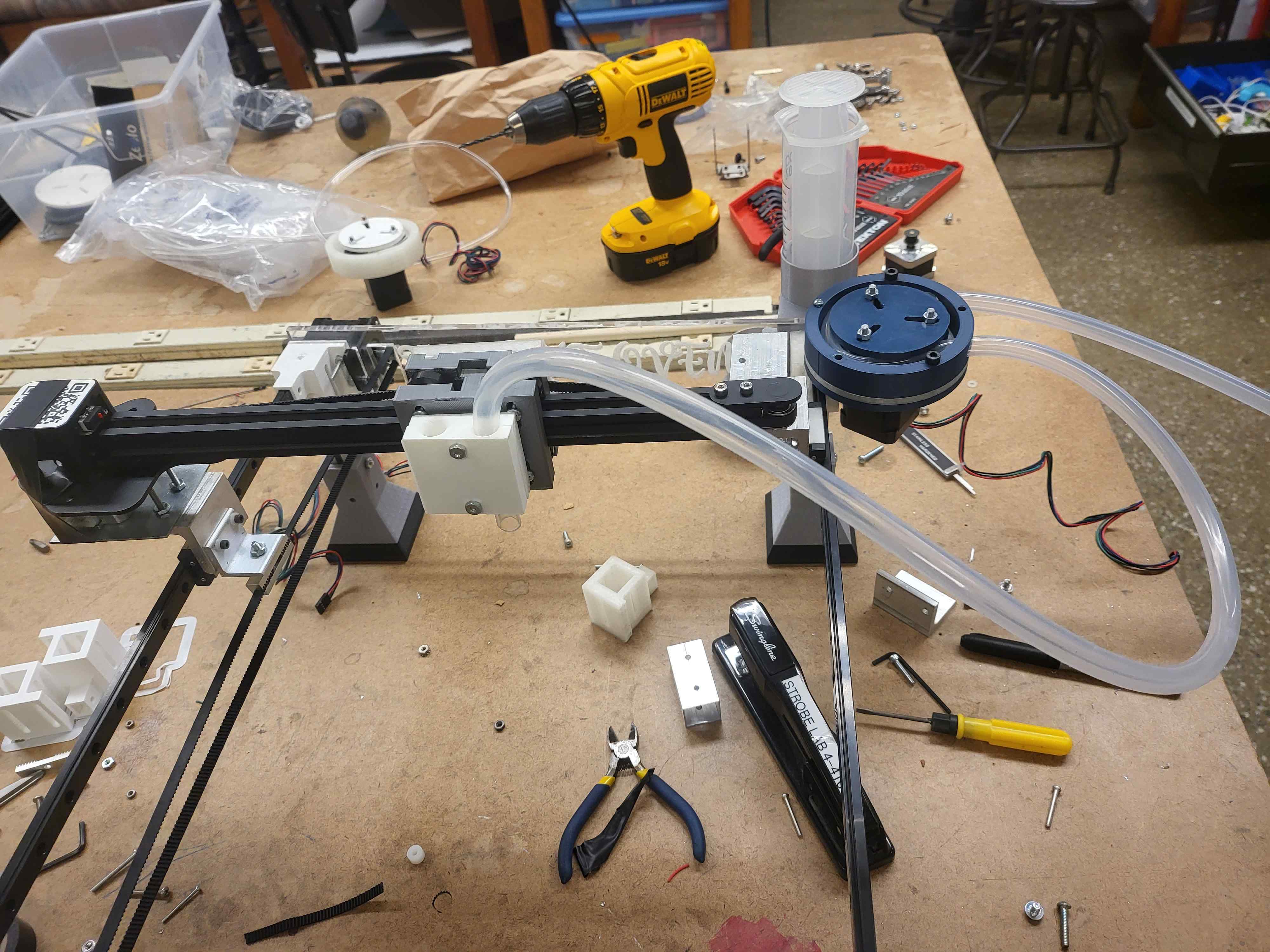
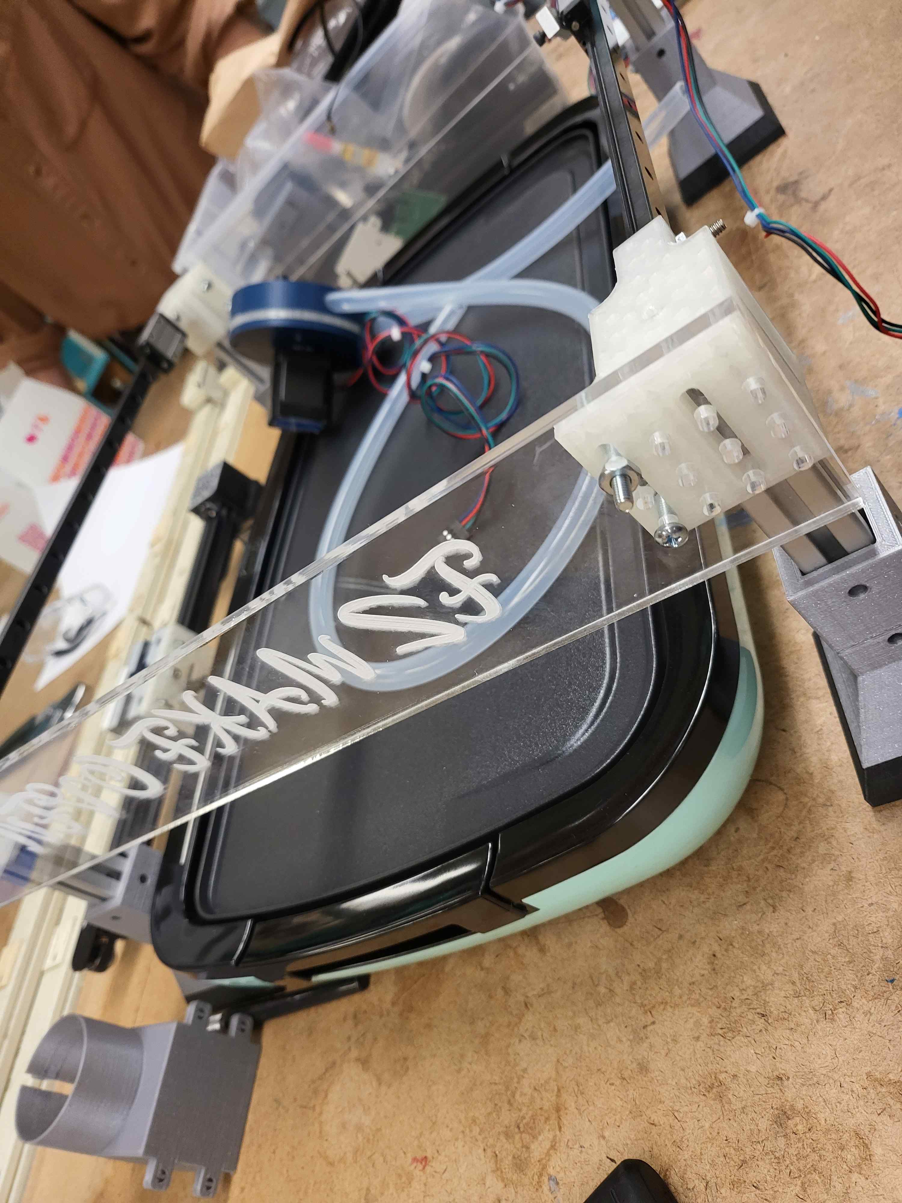
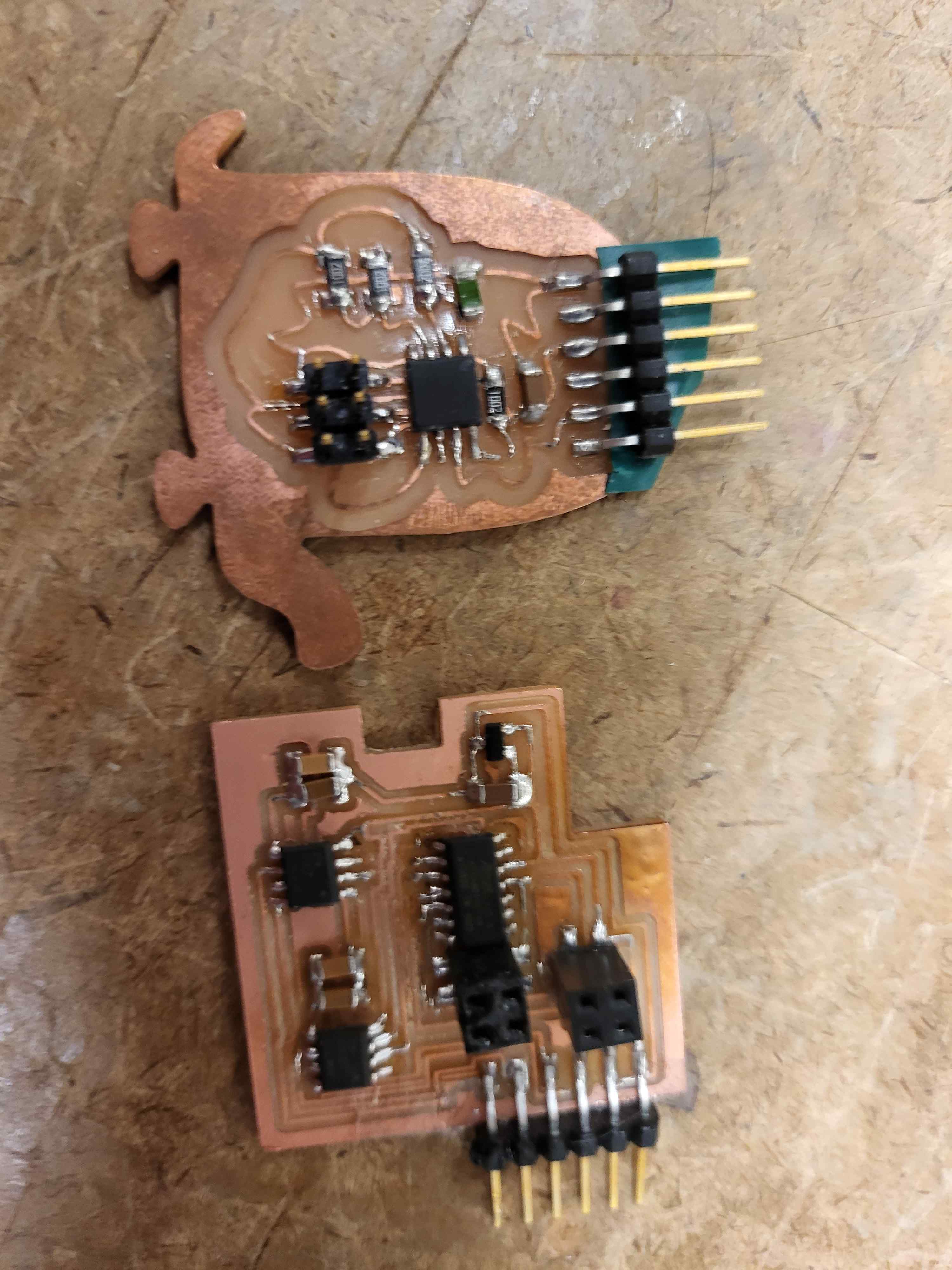
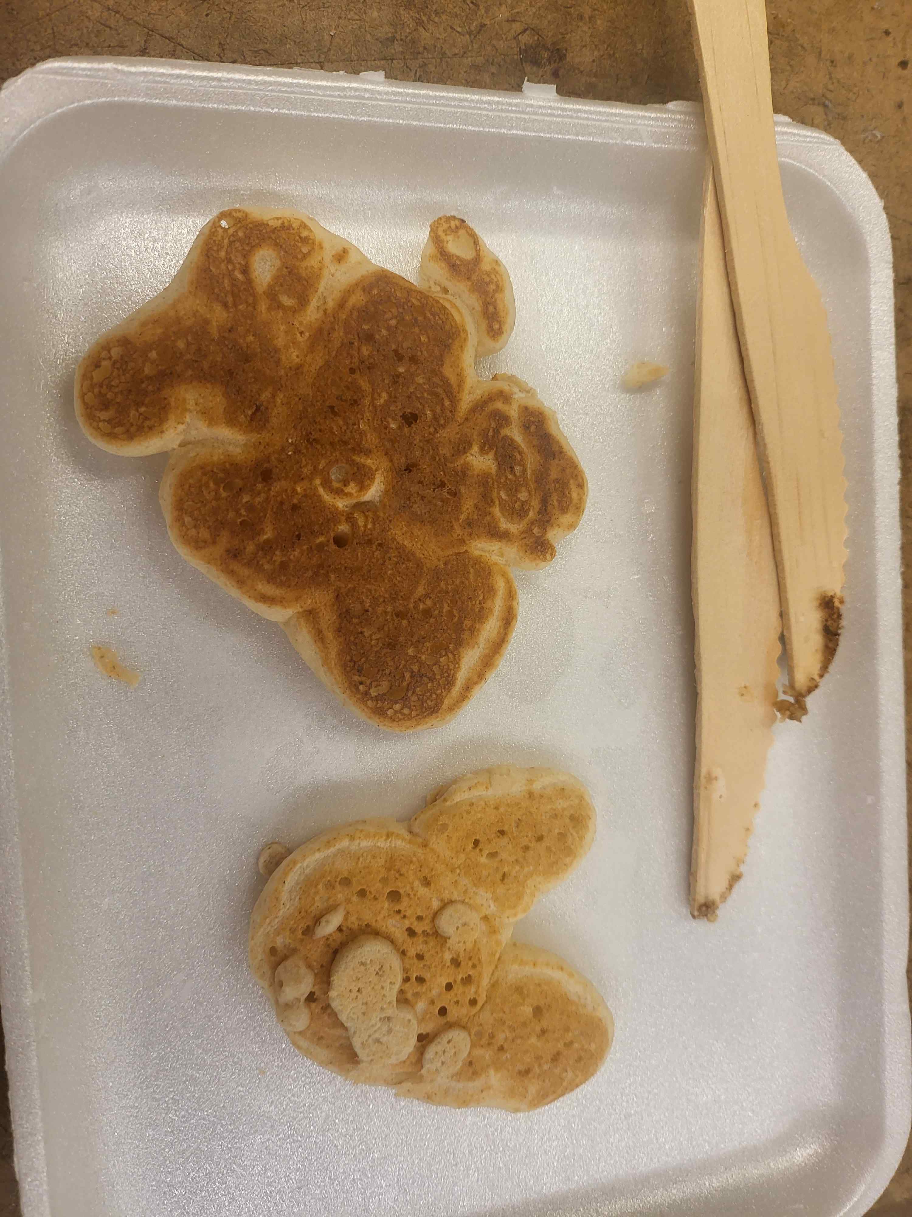
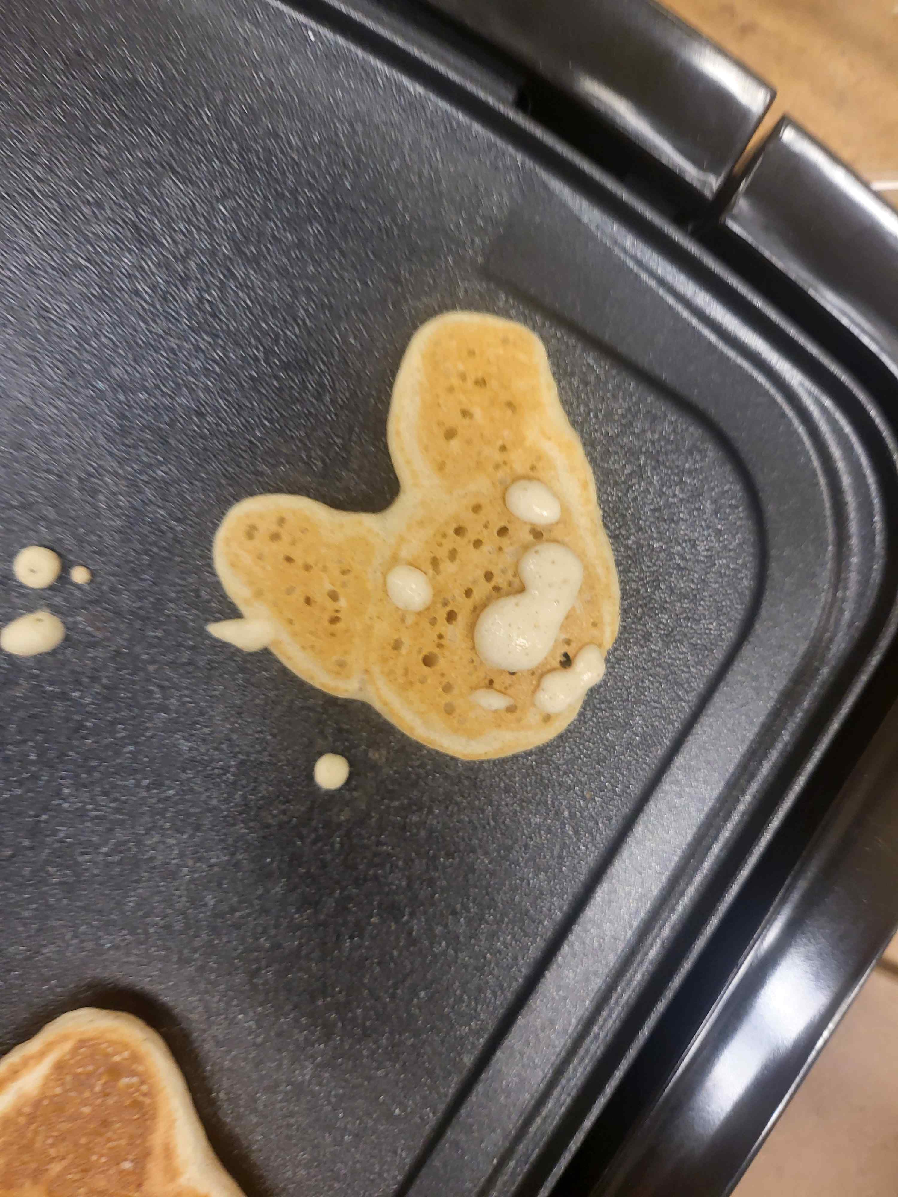
Pancake printers exist already, but my future goal is to have it create slices of 3d objects that can be assembled and the dual extruders allow for many more options. I designed stepper boards, a dev board, the frame, the gantry, and the modular version of the peristaltic pumps (based off the design from machine building week). I also used modular things to help with my course 6 inferiority. The griddle cost a lot of money but only because I wanted the blue one, and the steppers, syringes, and slides cost a bit together as well, but factoring out the cost of the griddle (it was neccessary for my project but ideally it would just interface with one responsible adult people who have to feed themselves already have) so the total cost was less than $100, (the steppers cost $55 by themselves). What worked was the gantry what most of the time works but is extremely sensitive and needs to be calibrated for every different pancake brand and recipe (really viscocity) was the peristaltic pump. I need to work more on presetting values for different pancake recipes and using the interface to allow you to choose between super thick to super thin batters. The control you get is also not the best so it's hard to make things, at least for me it was and here are some pancake prints to prove this.
Here is the Modular Things code I used
let Gantry = createSynchronizer([Xaxis, Yaxis])
console.log(Gantry)
Xaxis.setCurrentScale(0.75)
Xaxis.setStepsPerUnit(30)
Yaxis.setCurrentScale(0.75)
Yaxis.setStepsPerUnit(50)
Pump.setCurrentScale(1)
Pump.setStepsPerUnit(20)
Xaxis.setVelocity(100)
Xaxis.setAccel(100)
Yaxis.setVelocity(100)
Yaxis.setAccel(100)
Pump.setVelocity(100)
Pump.setAccel(100)
// let's do... get-set
loop(async () => {
let posns = await Promise.all([Potent.readPotentiometer(0), Potent.readPotentiometer(1)])
posns[0] *= 100
posns[1] *= 100
await corexy.target(posns)
Pump.relative(1)
}, 100)