Week 11
Networking Devices
Board 1: Design
This week I decided to do something that I had been putting off for a while, build a dev board. Previously I had made a new controller board for every week, but after looking at past documentation I decided that having one board I can add modules to would be best. For the microcontroller I chose the SAMD21 because it had the memory capcity and versatility I was looking for. That's when the problems started. I first tried to create the board on Eagle, but the routing was really difficult, I had trouble telling what pins were beside what pins because I didn't have a specific location I wanted them in, I just wanted them in whatever position was easiest to route. In the end I switched to using Illustrator which made quick work of routing I simply connected the SAMD21E pins to breakout connectors. In the interest of size and to make soldering easier I left some pins unused.
Board 1: Milling and Soldering
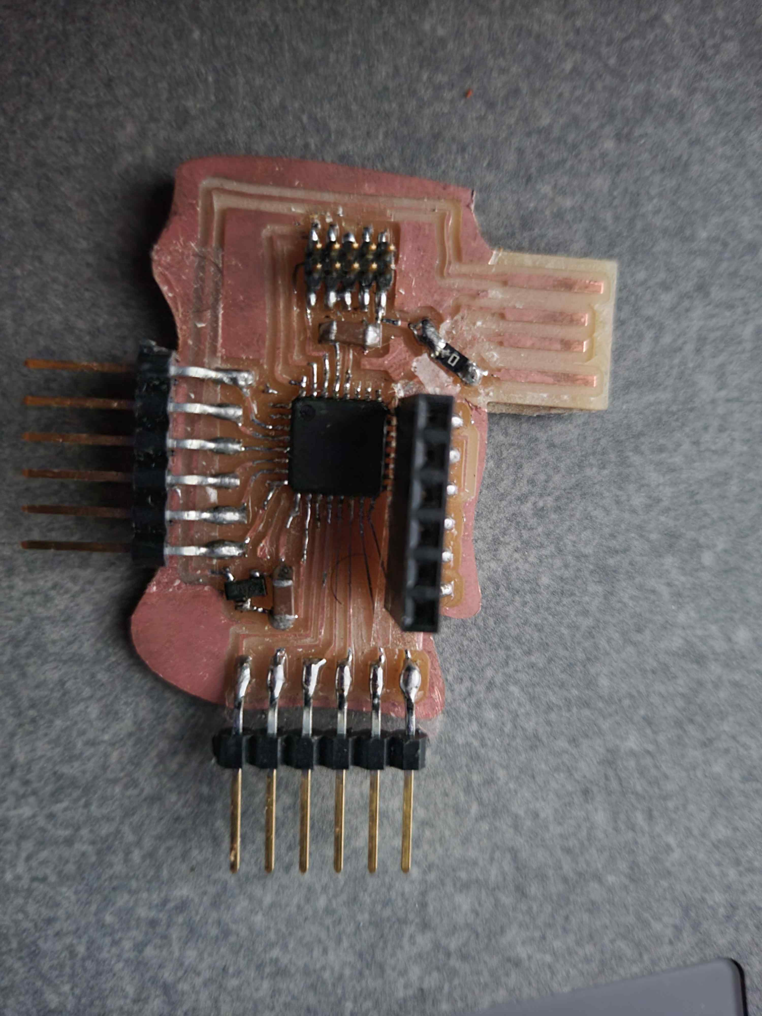
When milling my board I ran into a few problems. Last week my traces were much too thin and gave me all kinds of problems, so this time I made them thicker, but whilst doing this I accidentally put some of them too close together. After augmenting the png several times to no avvail I decided to take an ill advised approach. The DRC we use in Eagle has the minimum distance between wires set to 16 mil and the smallest endmill we use is a 1/64th inch which corresponds to 15.6 mil which is a very small difference I wasn't off by much, just enough for mods to not create a path through my SAMD21 pads (which are unbearably close). As a solution I changed the size of the endmill in mods. This is ill-advised because I essentially just lied to the machine to get it to ingore the problem. Here are my findings: setting the size to 12 mil destroyed everything, all of the paths created overlapped and cut into the traces, 13.335 was a close call, it worked but the paths were really thin, 13.5-14mil was just enough to correct for the errors whilst still keeeping the traces I needed. Needless to say I milled several and I do mean sevral boards until I finally got this part down. Then it was off to soldering, I used the soldering wick trick on SAMD21 pads and everything was going well until I realized my design had a major flaw. I had pins pointing out at the usb port meaning that it couldn't ever be plugged in. My board broke as I tried to fix it, so I made a new one and replaced the horizontal pins with vertical ones. This ended up working quite well with a trick I picked up earlier in the semester, using tape over traces I don't want to interfere with to keep my boards compact and to make insane jumps with 0 ohm resistors. When I went to flash my board I realized I had major issues with the amount of solder I had sucked up and added more solder to the pins, this time carefully one by one to ensure that they were all Soldered and soldered down well. Flashing was a nightmare, I couldn't get the computer to flash my board despite following the MTM EDBG tutorial. This was the point where I had to course 6. I've learned so much about troubleshooting technology in this class whether it's getting the mill to work or EDBG to cooperate. The problem was how files were stored on the computer, the code we were given was loooking for something somewhere where it wasn't. So I made the folder it was looking for, added the necessary files on the inside and flashed my board. It didn't work at first, but after being a bit more liberal with solder everything flashed fine.


Boards 2 and 3
I was fascinated by the recitation on what we could get our boards to do, so I decided to design a keyboard for this game I love so so much and am borderline okay comletely obsessed with but it's not a problem if you acknowledge that it's a problem. My original idea was to create a keyboard with 12 buttons corresponding to the 12 cards in the game that are already interfaced and mapped to keyboard shortcuts. I got a far as designing the board without hiccups, I simply used the template that was provided for us but used 12 buttons instead of 15. I liked the giant ground this board featured both for it's visual properties and ease of routing so I added this to my design as well adding a bit more art to the board design. The problems started when I tried to mill, I had the same problem as earlier with my traces and looking back I think it may be an issue with my pad library. Anyways I tried the lie to the mill trick and it did NOT work. Everything was destroyed and I couldn't find the sweet spot the way I did last time. The main problem with this board was that it kept failing and took an hour to mill. I made 6 attempts whilst editing the file before deciding that due to a combination of factors including but not limitted to broken endmills, a badly designed board, and demand side time reasoning I had to postpone this idea... for now. My next board was just a simple TFT board, and its fabrication was going great. I milled, soldered, and stuffed it in record time. I am getting so much better at soldering even with the tricky SAMD21... or at least I thought so. I flashed this board first try, and when I plugged it in the TFT screen immediately lit up, but then disaster struck. I tried to remove the screen for transport and ripped up all the traces.


Conclusion
Though my SAMD21 boards flashed ok, they weren't discovered in the arduino ports. I looked into this problem but couldn't figure out a workable solution. I'm improving quite a bit at the hardware side of things, but software's still giving me tons of issues. I'm typing this in a local copy of my website, and I now have css and javascript added, but I still have a lot to learn on this side of things.
