Electronics Design
PCB Design
This week we worked on PCB design, I've never used any PCB design software before but I know a bit about circuits from an intro to circuits class I took last spring. The assignment was to redraw and echo hello world board and add an LED and button, which sounds pretty simple but ended up being quite hard a time consuming. While scavenging the vending machine outside of Metropolis, a makerspace I consider to be my spiritual home, I found an Adafruit kit to make a mini POV. POV stands for Persistence of vision and means that you take advantage of human weirdness to make a line of LEDS form an image or grid when moved rapidly from side to side or spun. Here is a picture of the completed kit/device.
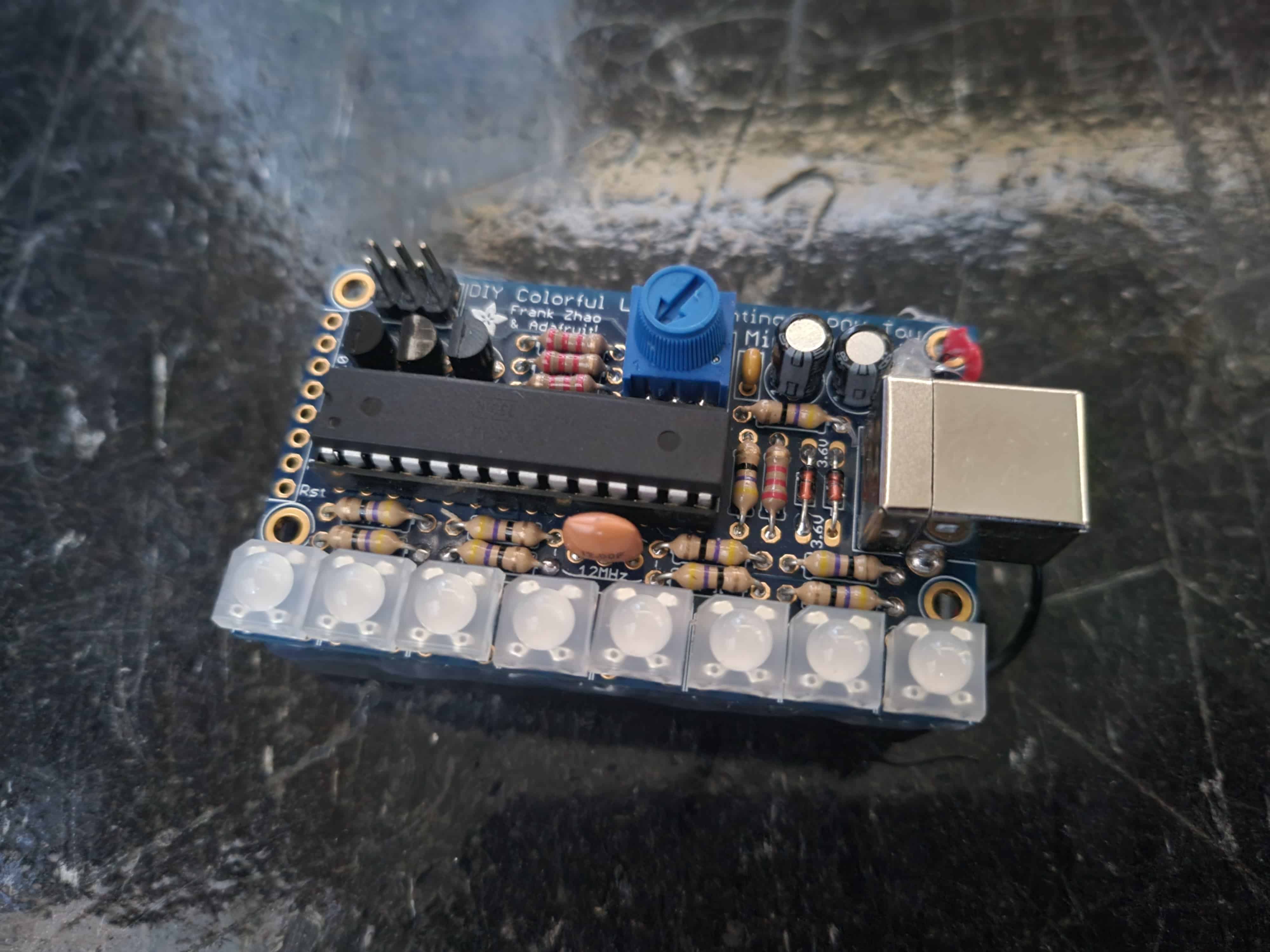
I wanted to make one of my own, and maybe stick it into a 3d printed lightsaber so it would say something when spun, but I ran into some road blocks along the way. Originally I wanted to use the lab's rgb leds so I could have every LED in the line be any color and change into any color, but that would take so many pins. I researched this cool techniques called Charlieplexing (n^2-n leds for n pins) and multiplexing (n^2 leds for 2n pins) to get more LEDs for my pins, but in the end I took a shortcut and used neopixels. Neopixels are great because they have their own led driver, are individually addressible, and only take one pin for roughly any size strip. Everything was going great, then I thought about creating a USB POV and realized that it didn't make sense but if I provided an external power supply it would be freed from the usb dock to spin as it chooses.
Cadding (but not the fun 3d kind)
The software I used is called Eagle and is conveniently located inside of Fusion. Which is great right? I love Fusion, and Eagle is now a part of Fusion so I no biggie I'll probably love Eagle too. I was wrong, way wrong. I found Eagle a lot harder to work with than Fusion, but that's probably just because I wasn't used to all of its little quirks. Success is a horrible way to learn something, by which I mean instantly suceeding at something doesn't teach you a whole lot about troubleshooting and everything isn't always going to turn out 100% perfect the first time. Or maybe that's just what I'm telling myself because I had to restart my Eagle design... like a lot. This was mostly due to equipment error, my computer died on me this week :( but also had something to do with bad design decisions. I remade the board 8 times which was extremely frustrating, but I got faster every time so I guess I learned something.
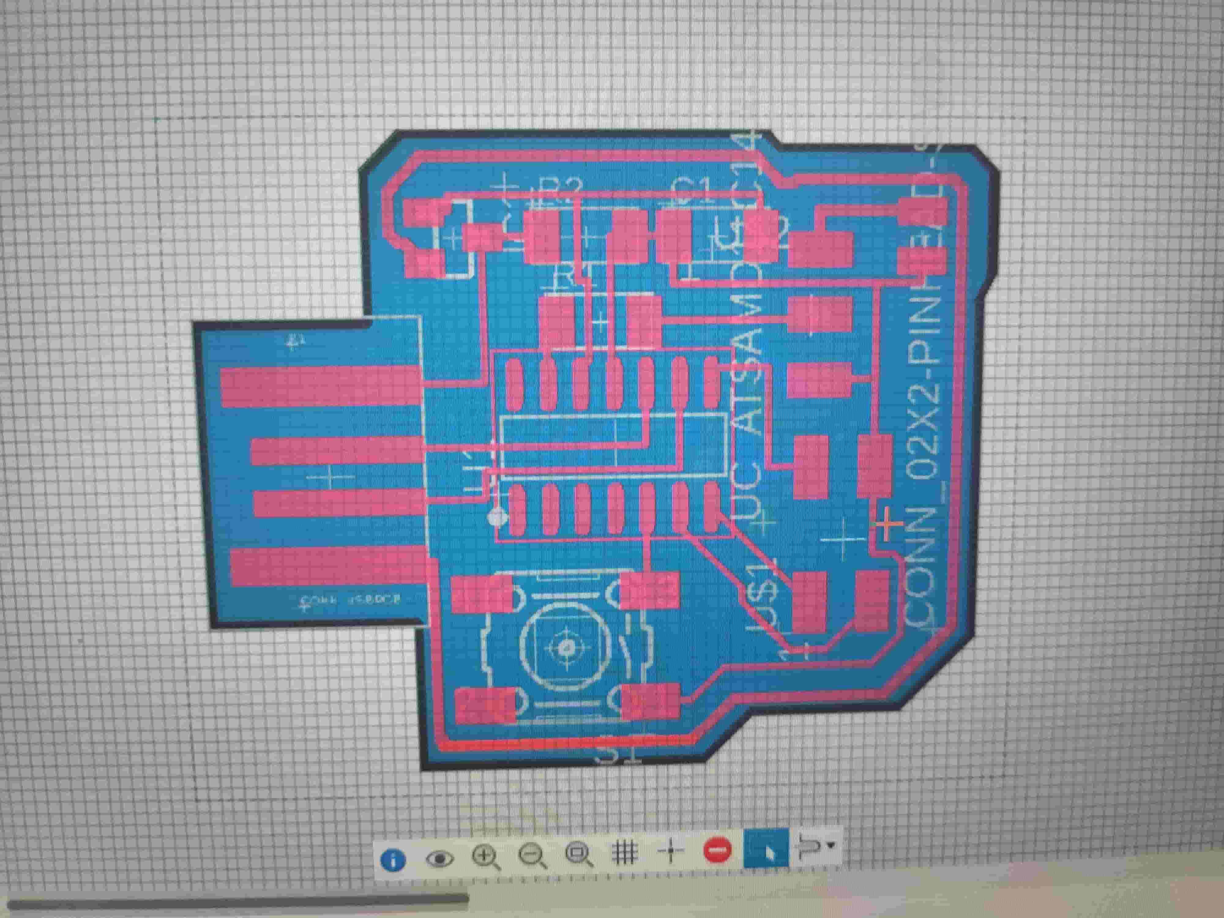
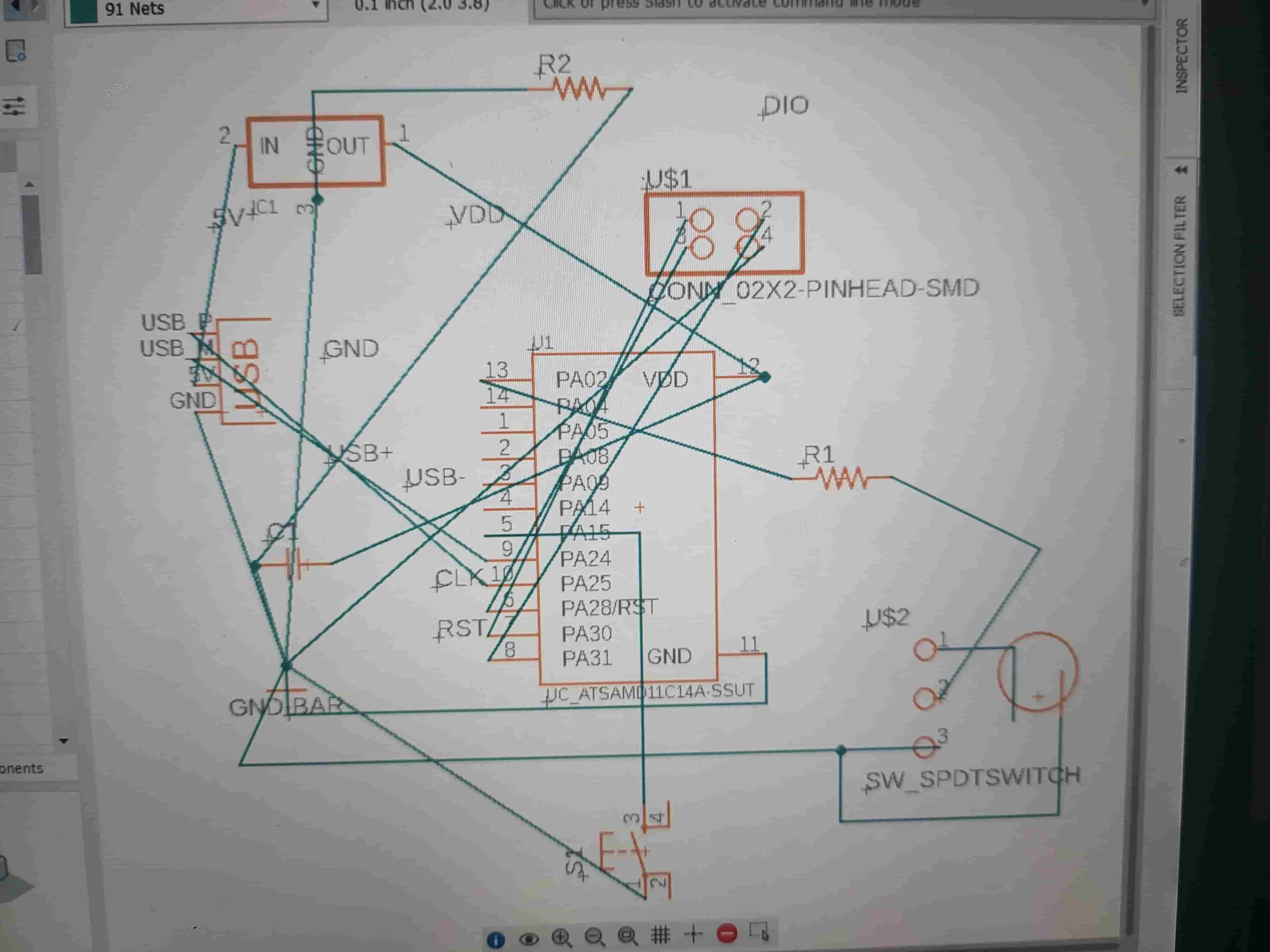
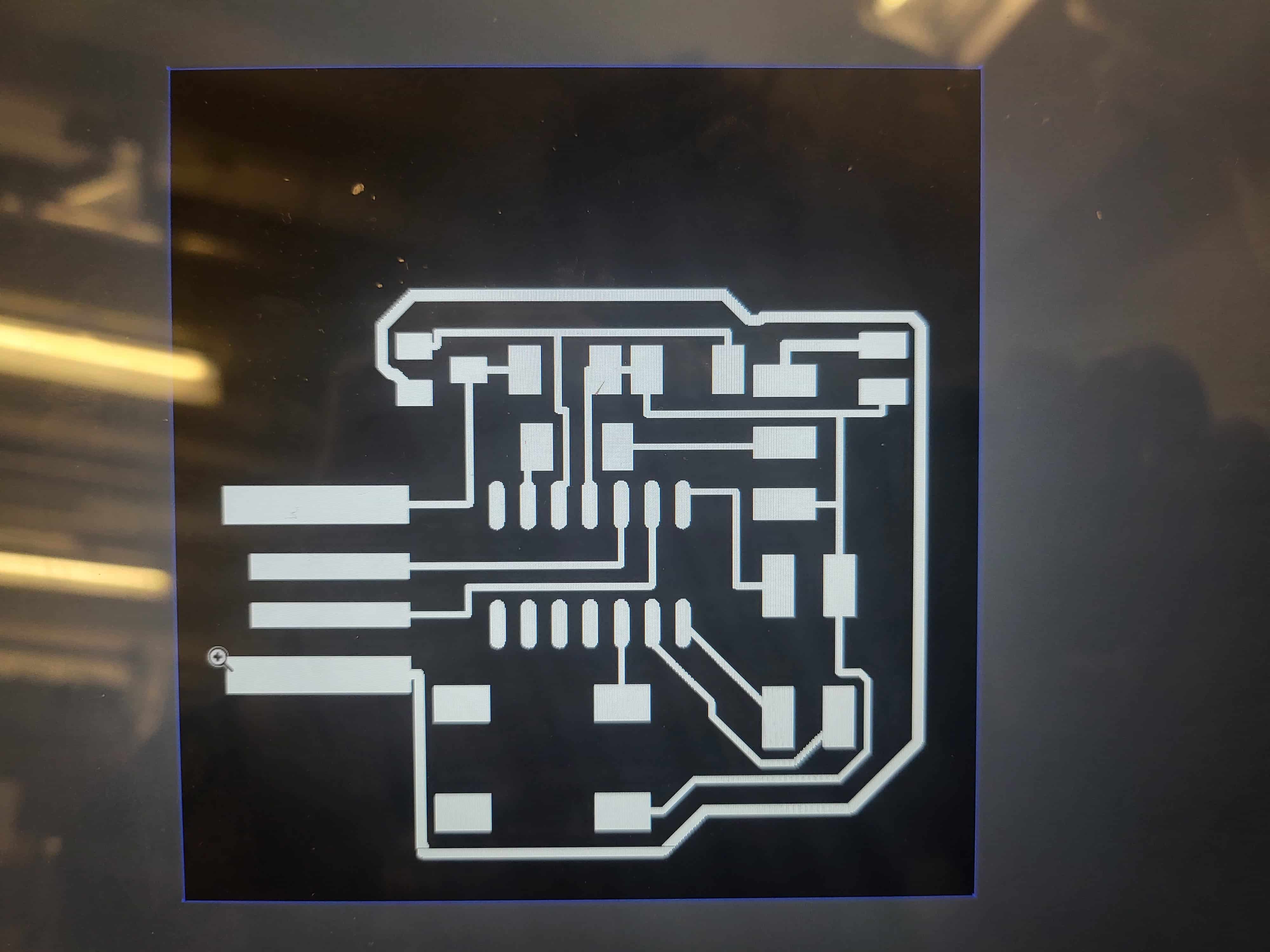
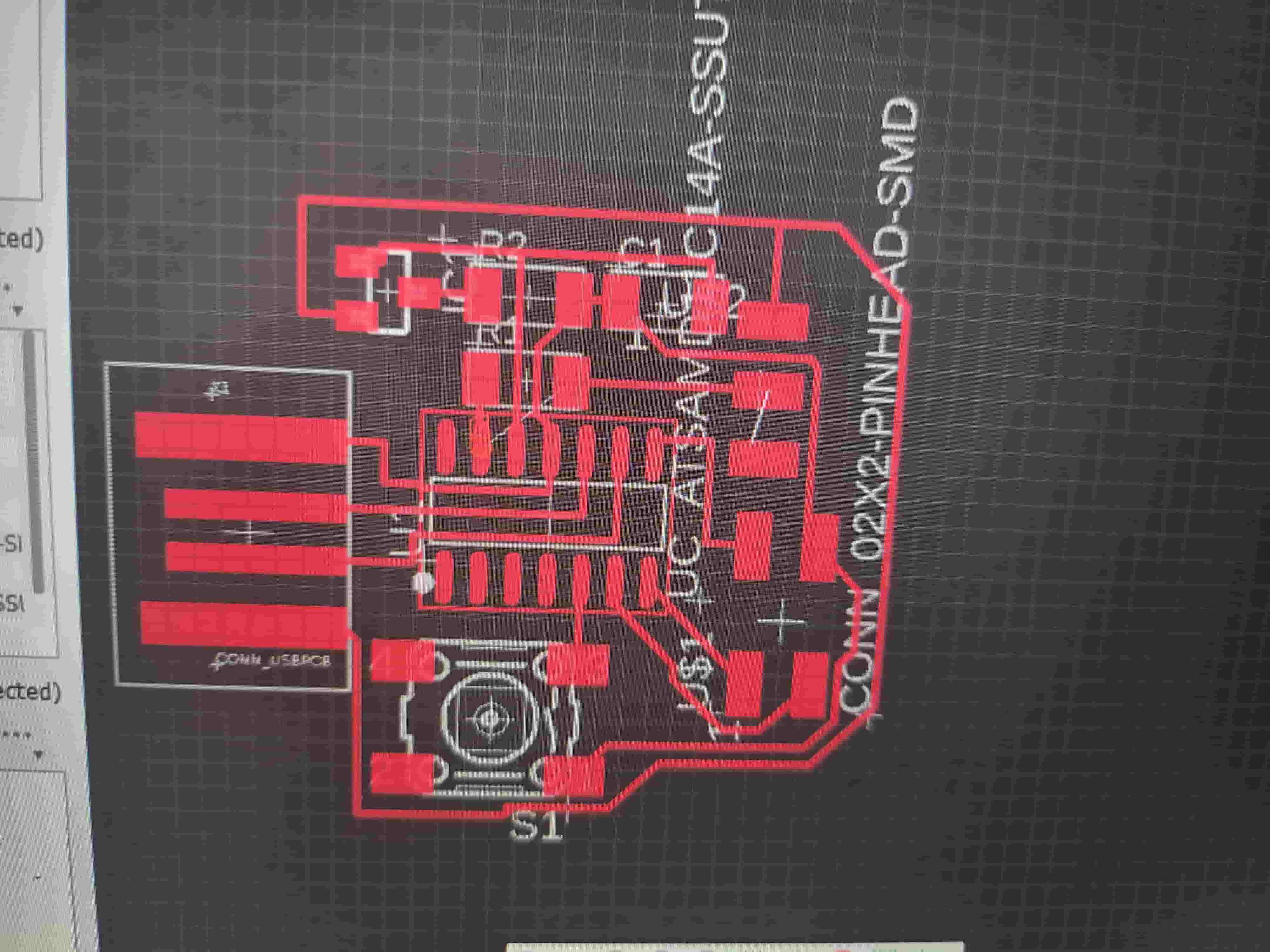
As long as you do your research the schematic is the easy part of Eagleing, the hard part is actually configuring the board. Its like a really complicated puzzle that might just be impossible but you never really know until you complete it and realize that the last piece you're holding actually belongs to an entirely different puzzle you now have to solve. All this to say, you have to think way ahead when you route your board. For starters it helps to move all of your pieces close together and arrange them so that most of the net lines from the schematic are closeish to each other. Now observe what you have done and scour your part list for bridges or pieces that you can go through, these are helpful for avoiding crossing wires. If you don't have any bridge pieces then you might want to mentally prepare to add 0 ohms resistors (pro tip) or vias. I ended up using two 0 ohm resistors, but because of weirdness with my board design I only really needed one. It's not really worth planning around design problems, I worked really hard during post processing to fix mistakes made during this process, be better than me and take the time to go back to the beginning and do it right. My traces were far too small and that made a lot of things difficult, I thought I could ge away with it and I did but it wasn't worth all the extra trouble. Here are pictures of my EEagle designs and the actual PNGs I used to mill. It took me a long time to figure out how to export PNGs but I found it in the recitation notes and cleaned up the files in illustrator.
Milling
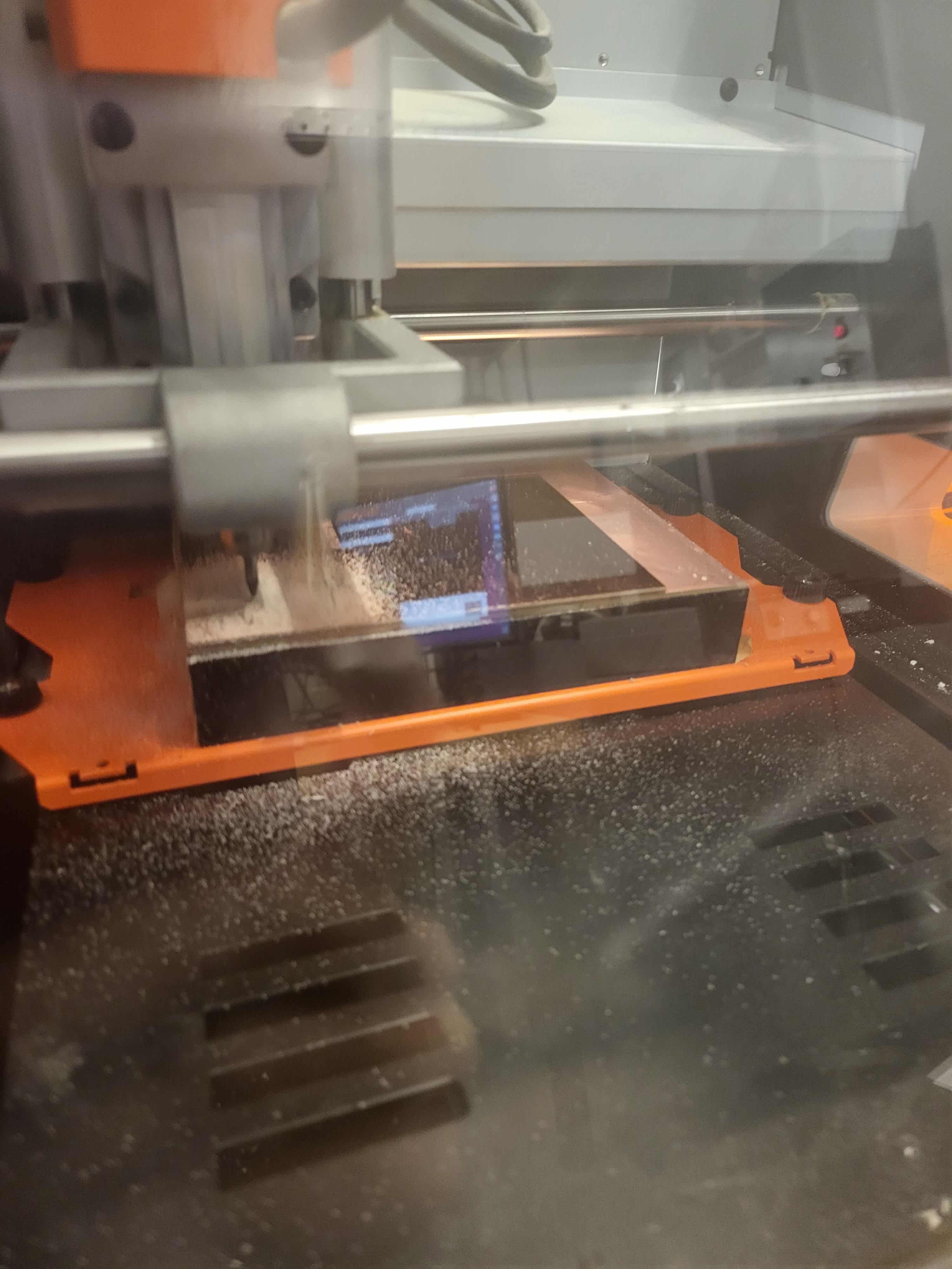
Milling went a lot better/faster this week. I didn't mess up at all (during this part) but did have to mill twice because the programmer broke my PCB's traces. Here are pictures of the milling process, I used the Modelo with Mods again.
Soldering
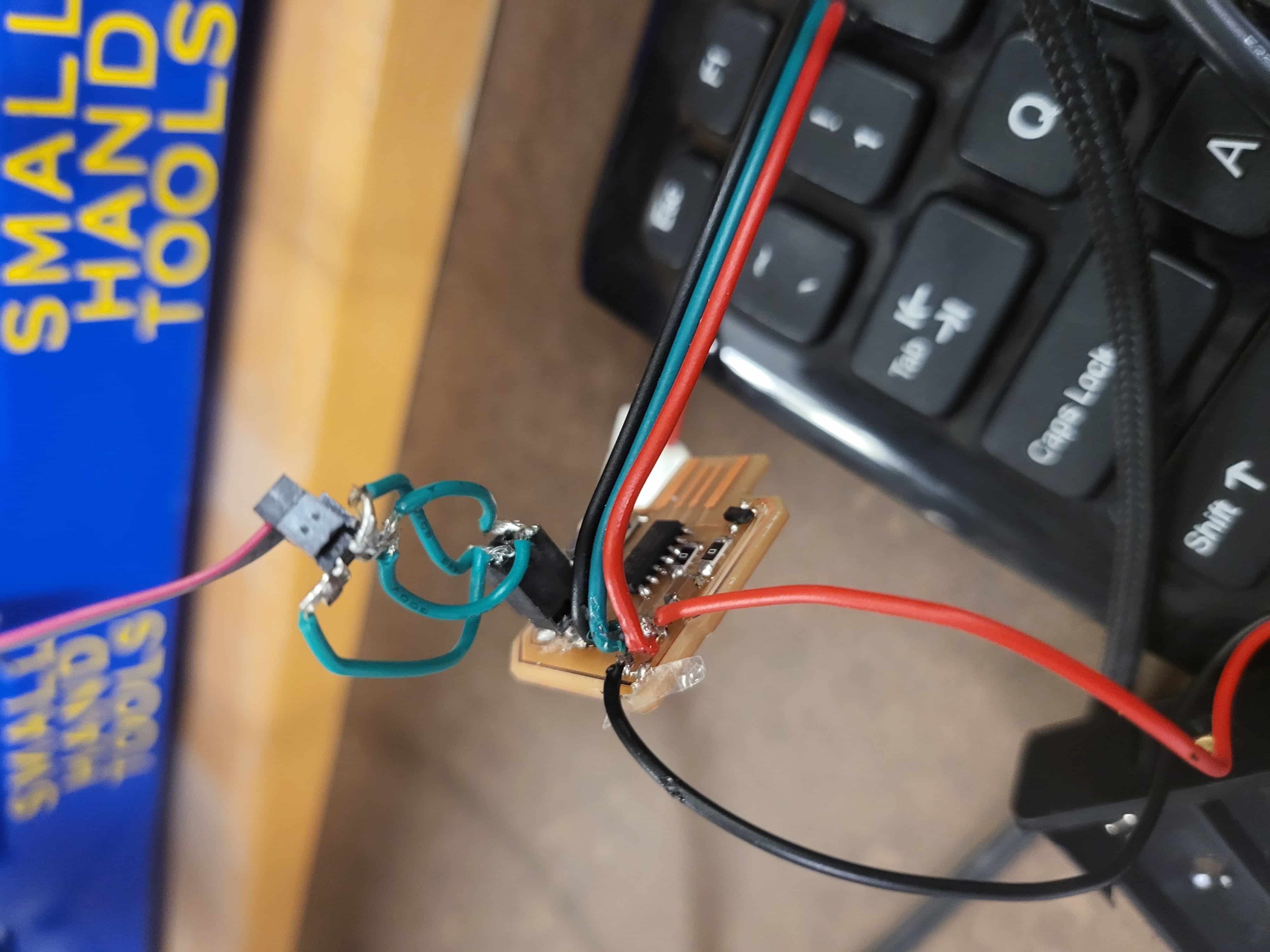
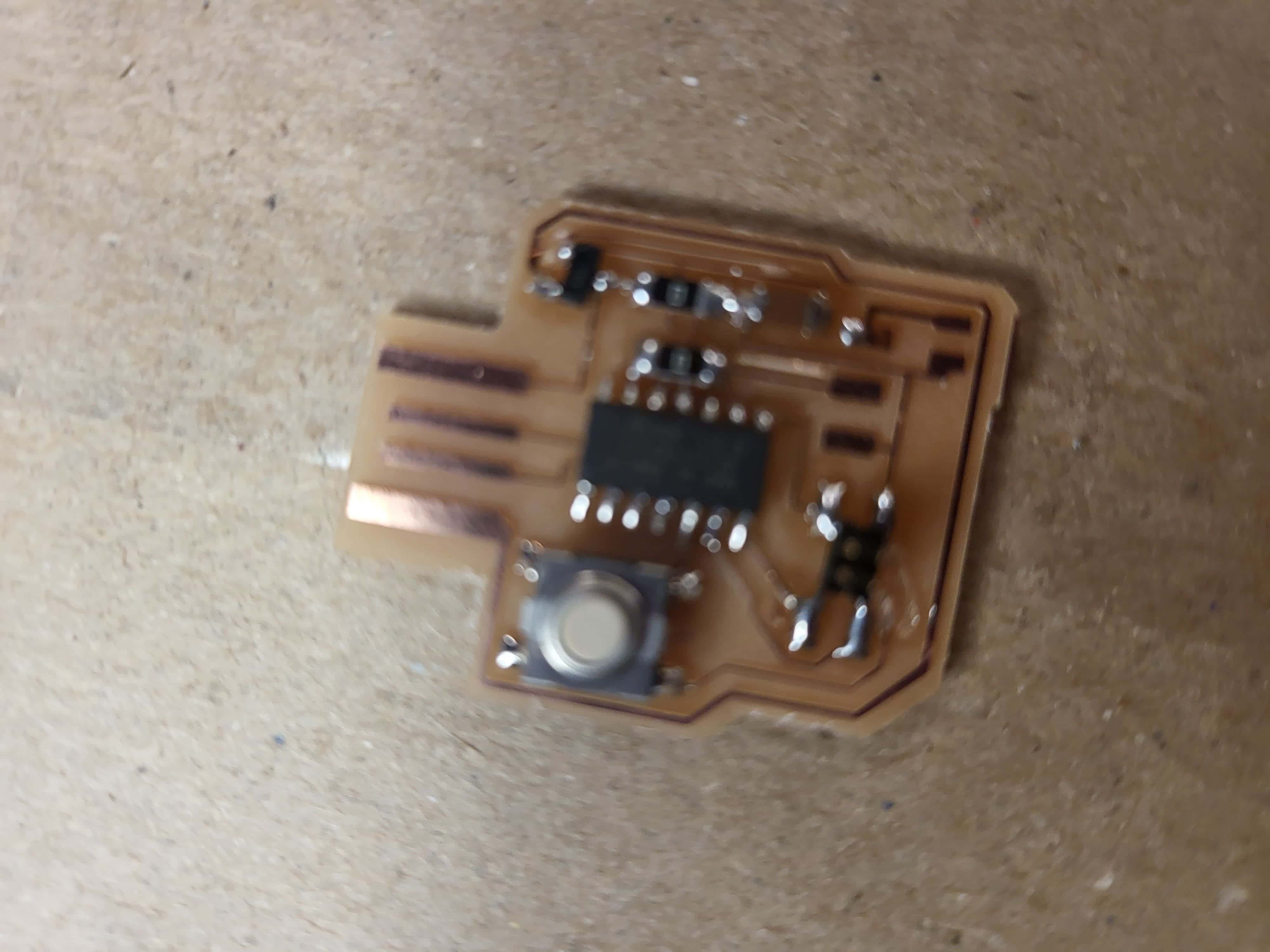
Despite the pieces being super small, soldering went amazingly smooth and using the same technique as last time with magical leaded solder I was able to get everything soldered nicely and checked for any errors using a multimeter, which isn't the best tool for the job but did provide me with relief that at least it looked and sounded right. Soldering was actually pretty fun this week, well at least the first time. I was too frustrated the second time to enjoy it. Also soldering wires onto tiny traces is hard, the strands one the neopixel connector and the power cord just kept on melting off and being in the way but eventually I got it (the first time rather beautifully the second... at least it works). It took me a while to realize that instead of finding parts with similar layouts in Eagle I could've just manually connected the wires to the parts eliminating the need for one of my resistor bridges and so many solder globs. heres a picture of the first board followed by a more depressing picture of the second
Programming: AKA The Moment of Truth
The programmer was really tight on my pins and ripped the traces off before I could do this part and so far I've been scared off programming but I'll give it a try during programming week. I want to get the board working soon though. Also I don't know how to program my board because I chose one with a 2x2 connector and there are no programmer cables that connect to this, I tried making my own, but like I said it murdered my POV.