Input Devices
Temperature
I still want to make a pancake printer for my final project, I'll simplify to just 2 dimensional and in
light of this assignments exposure of my horrible, yet improving, skills with electronics I might just have
four preset shapes you can print. Of course those shapes will be turtle, dolphin, narwhal, and triangle. But
I need to know how hot things are, and by things I mean the extruder, the griddle, and the elctronics next
to all these hot parts so I need to have a temperature sensor. I'm tempted to build a mechanical solution,
but as scary and hard as electronics are I want to know how to create them. So I chose to make a temperature
sensor. More specifically I decided to create a derivative of Neil's temperature sensor that's on the class
website.
Who Needs Eagle When You Have Illustrator
I was out for most of last week and had to make a few simplifications to catch up on both this assignment
and the molding and casting assignment from last week. The first simplification I made was drawing my
circuit instead of cadding it on Eagle. This might not sound like a simplification or a good idea, but I'm
more familiar with Illustrator so it sped up my process and really taught me a lot about how Eagle works. I
started by getting to scale images of the traces for individuals parts into Illustrator. I then grouped
these images together and gave them their proper names in a master document containing all the parts I'd
need. It was actually tons of fun and I learned about layers in Illustrator and how to use those and how to
set names for groups. There's a tab on the right side that says layers and in it you can make layers the
sameish way you would in Eagle and you can toggle their visibility to export just the layer you want. After
creating a library of parts in Illustrator I looked at the size for my routed wires and copied the size into
Illustrator's pen tool so I would be creating lines of roughly the same size but a little thicker because of
all the problems I've had over the semester with tiny traces, I found that it correpronded to lines roughly
1-1.2pts thick. Then all the was left was to connect the neccessary pieces together which Illustrator made
super quick and easy, and I forgot to mention this but you can also name elements in a group so for example
I named both the group of connections for my Attiny45, tiny45 and the individual pins with the names given
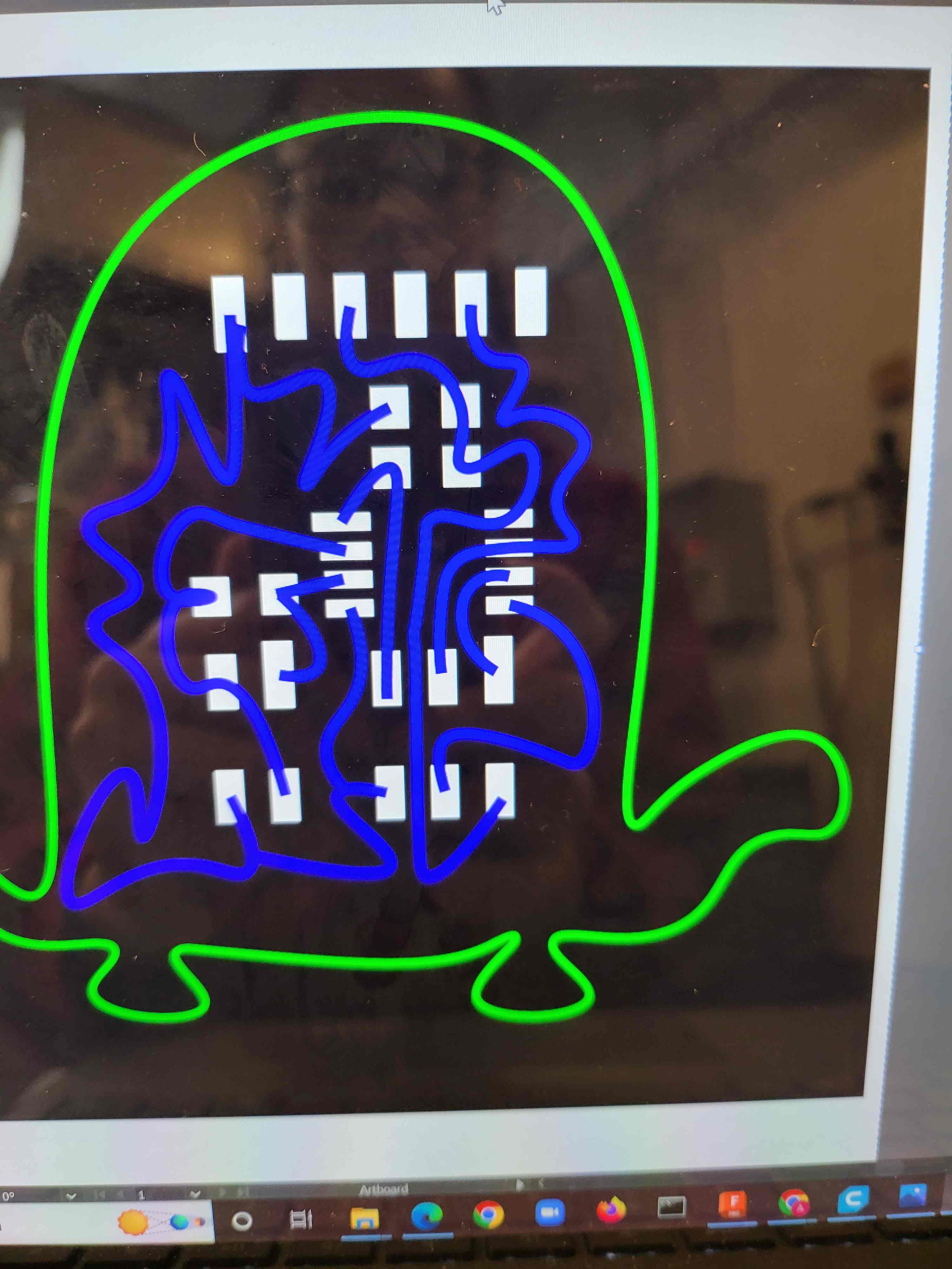
for them on the data sheet. And I got to make cute swirly lines (that the mill hated but I like) instead of
straight ones. All together a win win win, and I easily made a cute shape for my board.
Milling and Soldering: AKA the part where everything goes wrong
To make a long story short the mill wouldn't connect to the computer and it took me hours to figure out why
but with a little course 6ing I figured it out and fixed the problem. I'll write it here for future
generations or Archshoppers. The deviceserver file was in the wrong location so when you type in the code to
connect to it you get a "not found" error. You might want to search for it yourself to confirm, but I found
it in the modules/js folder so instead of typing "node deviceserver.js ::ffff:127.0.0.1 1234" you type "node
modules/js/deviceserver.js ::ffff:127.0.0.1 1234" and if that doesn't work you close out and type "sudo
chmod a+rwx /dev/usb/lp0" changing the /usb/lp0 for whatever it may say in mods. Then it will work... you're
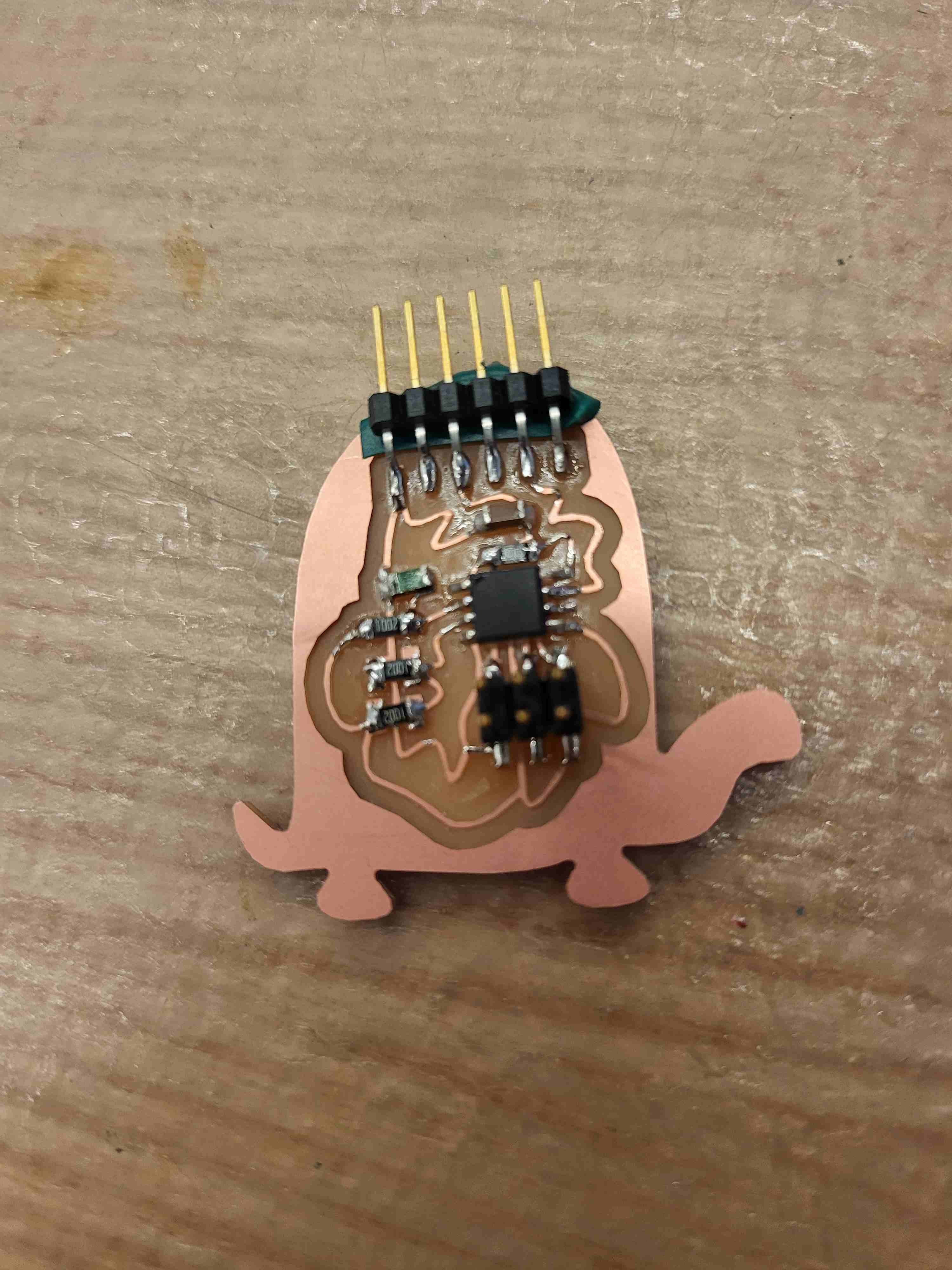
welcome. After that milling went smoothly and I had my TurtleTemp board, but apparently turtles are rounder
so it's a TortoiseTemp board but I don't listen to the haters so it'll always be a turtle in my heart.
Soldering also went really smoothly and is hardly worth mentioning except to say that the tips of the
soldering iron don't work if they're really burnt and dirty.
Oops: AKA I was being dramatic before but here everything everything really went wrong
To make a long story short I used the wrong template circuit and made the helloload board for step response,
luckily my handy Illustrator library saved me and I quickly editted the layout and remilled (I started it up
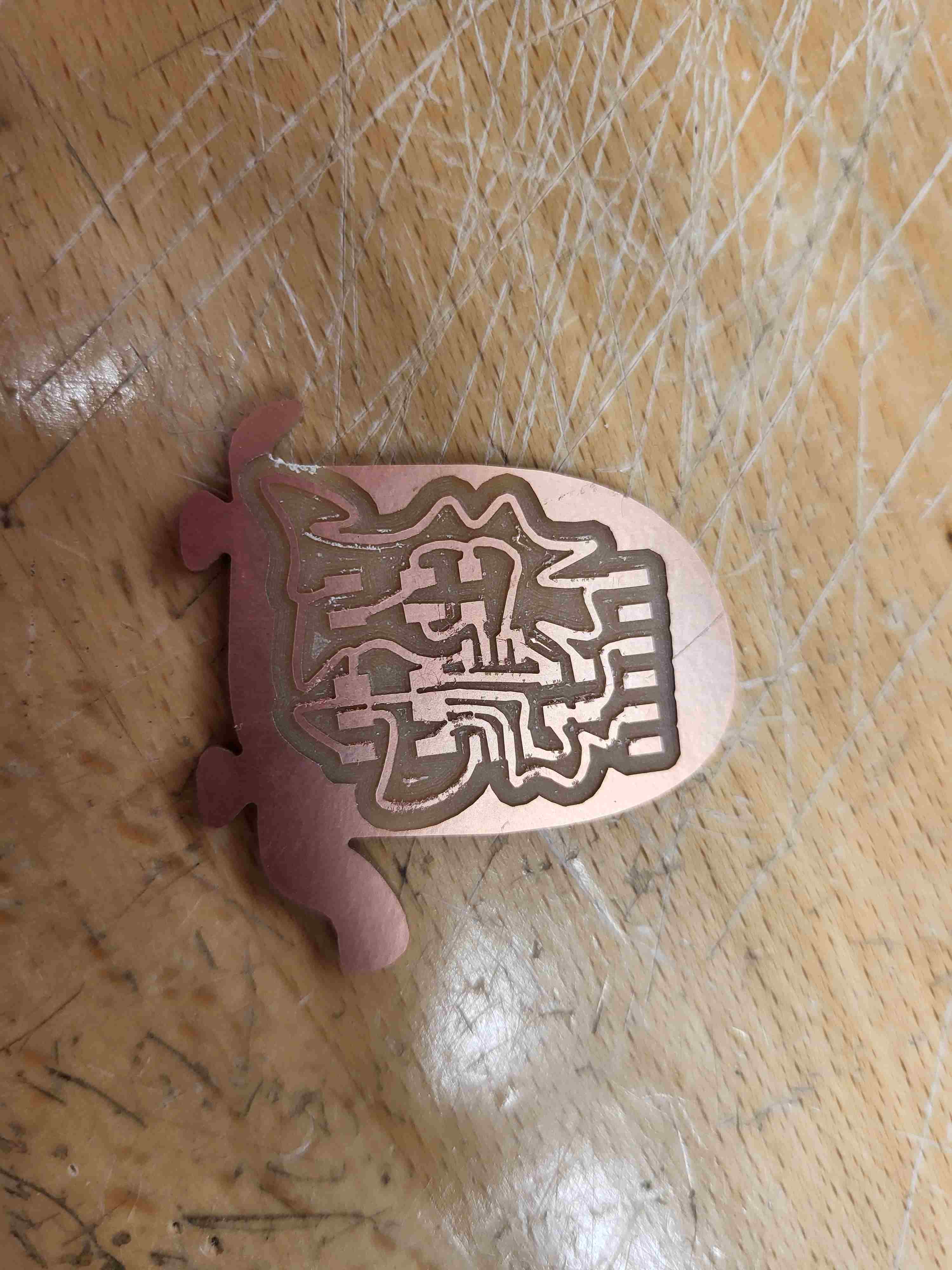
correctly immediately so it went a lot faster). I was rushing a bit and had to use an exacto knife to fix
some traces that had combined, I didn't mention this before but I took minimum distance down at the start so
my lines would never be too close. Finally I had a working TurtleTemp board. Now for the hard part.
Coding and Understanding
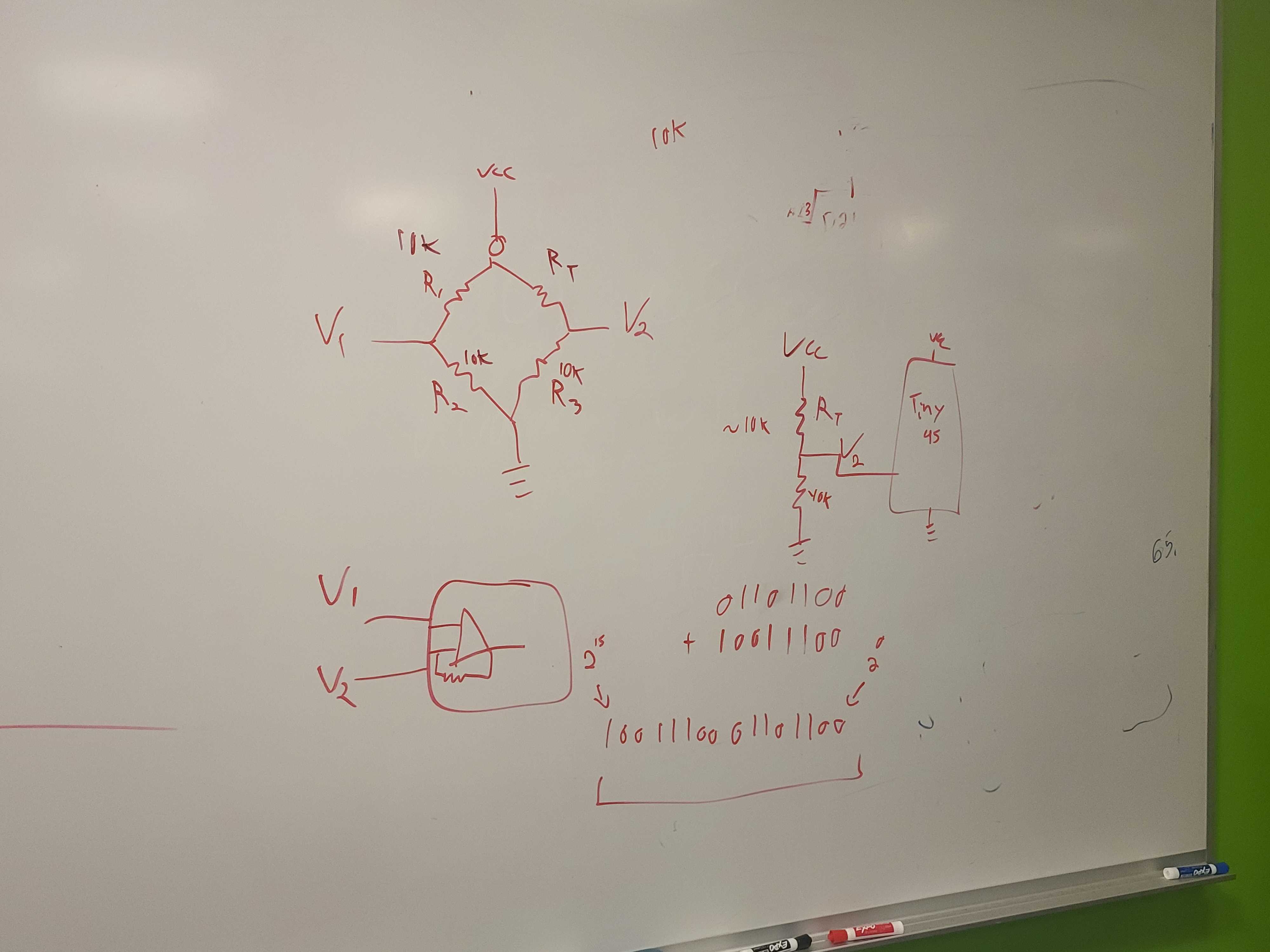
Thanks to a lot of help from Anthony I now understand the board. It uses a wheatbridge which acts like an
op-amp to amplify the difference between the voltage between two 10k ohm resistors and a 10k ohm reisistor
and the sensor which is nominally 10k resistance but that change by very small amounts with the temperature.
Temp increase=resistance increase, temp decrease=resisance decrease. I was not however able to get my board
working because of the microcontroller, Attiny45s are ancient and aren't easy to use with current
technology. I had to run it through the Atmel-ICE whilst powering it form the other side. I also had to
search the deep crevices of the internet for an ATtiny45 arduino board setup. First I got a you nees a
programmer error, then I pressed ctrl+shift+u which means upload with a programmer, then I got a board not
found error, I switched the wire around and still no luck. I hope to fix this later, but the best solution
is honestly just to use a better microcontroller, one that can interface with USB directly.
code attempt
Group Assignment
I was out for most of this and did the group assignment alone. I used a temperature sensor and observed how the resistance changed with temperature, there were very small fluctuations so I had to amplify it with an op-amp. I also learned that my fingers are not warm enough to dramatically increase the temperature of the sensor and that this though uncommon is not heard of and has something to do with blood circulation. I had to warm the sensor with my upper arm.