Electronics Fabrication
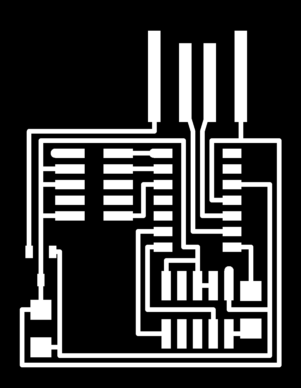
This week's project entailed manufacturing an in-circuit programmer. The Design was already made, and can be found on the CBA site (here) The images below show the traces(Left) and the board shape(Right). These PNG images were used to create the machine toolpaths. A 1/64" dia. flat endmill was used to cut the traces, and a 1/32" dia. flat endmill was used to cut out the board from the stock. The stock began as a flat sheet of fiberglass with a thin copper film, which eventually became the circuit board traces and solder pads.

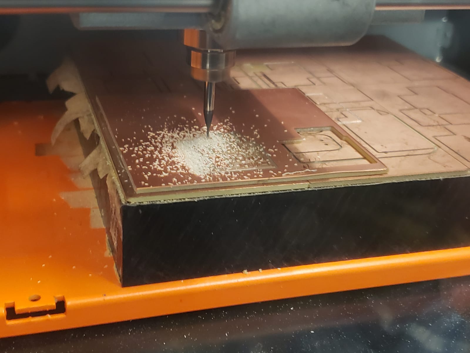
The board was cut on a Roland cutting machine. The 2 cutting paths (traces and interior) were cut using the different endmills from the same starting origin coordinates. I used 4 stepover passes on the traces cut, which left some copper leftover on the USB end of the board. This was easily removed by scraping it off with a knife. The traces cut very well, and the burr was almost unnoticable (thanks to a sharp cutting tool).
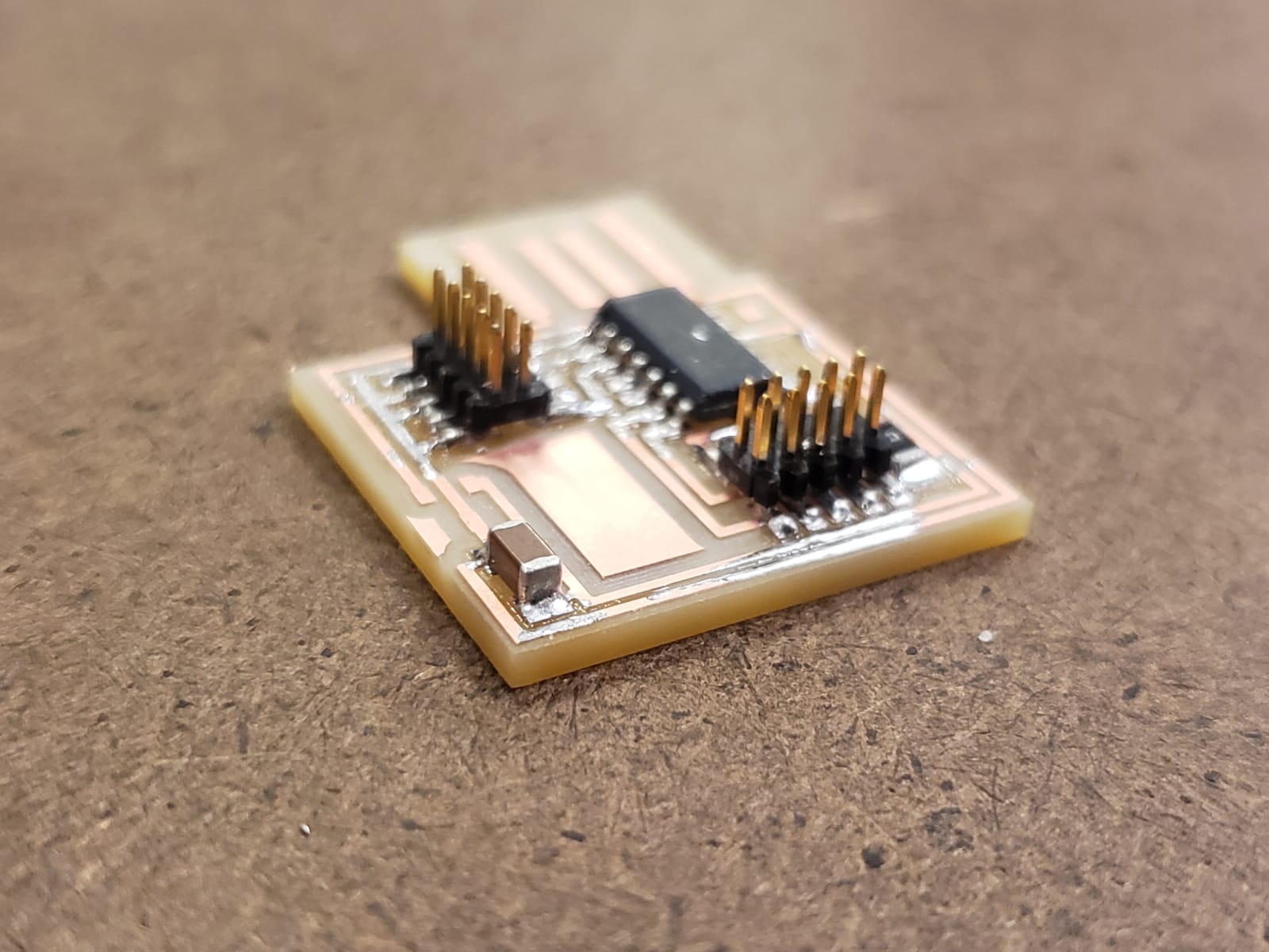
Soldering went pretty smoothly, but the most difficult part was positioning the components, and having them not shift around as I work. I also used a thicker solder size, which made it more difficult to control how much solder I added, which caused the solder to occasionally overflow onto surrounding traces. This didn't cause any functional issues, but I will use smaller diameter solder in the future.
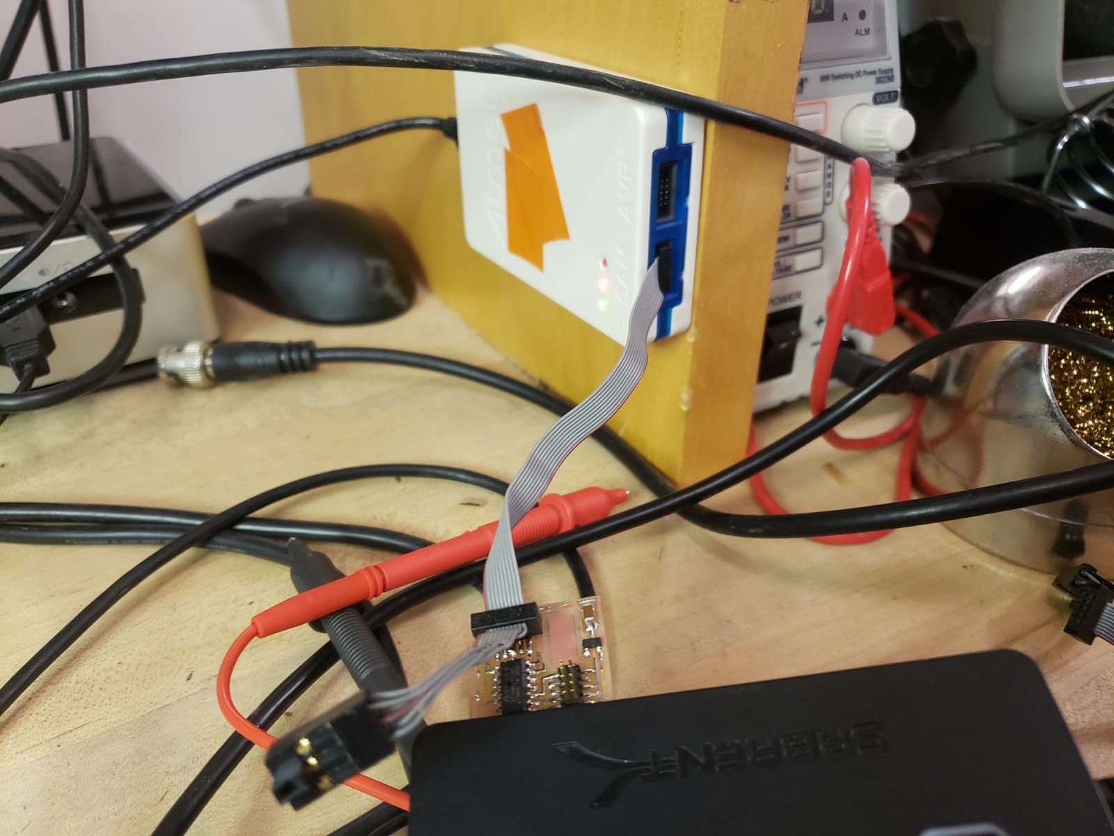
After soldering was complete, we uploaded the program to the board. There was an issue the first time we tried, and found that I was missing the voltage regulator. I quickly soldered it in place and (as the image below shows) the program uploaded correctly.
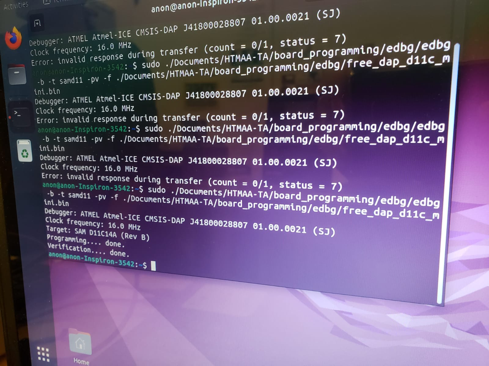
The green light on the programmer (in the image below) also indicates that the upload was successful.
Overall, I really enjoyed this project. I think the solder was my favorite part. I didn't have prior expereince with solder serface mount component (only through-hole), but it was a fun challenge, and I'm looking forward to doing it more on future projects.