week 10: output devices
Prior Experience: 1/5
i have made an led blink before. that is all
Week 10: Output Devices
I worked on trying to make a TFT module work.

For this week, I decided to use a TFT module, which is basically a screen that has colors.
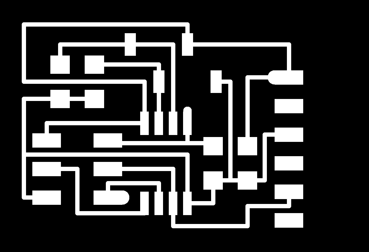
I milled the board using the traces/outline that I found on the class website.
Traces: http://academy.cba.mit.edu/classes/output_devices/OLED/hello.SSD1306.45.traces.png Interior: http://academy.cba.mit.edu/classes/output_devices/OLED/hello.SSD1306.45.interior.png
This file has a SAMD21E17 as the microcontroller, and has a connection header that lets you connect to the TFT display.
My first board did not turn out very well, so I remilled it. Here is the result:
I realized that something was wrong with mods so I just reloaded and milled again. It worked. I washed it with the soap in the molding/casting room.
I used the tweezers to roll and pull off the USB connector.

I realized that the 2x4 connector that alternated had legs that were too long so I cut them off with the wire strippers (it turns out these are not ideal; using an actual wire cutter works.)

I could not find the footprint in the fab library (I wanted to use them for my own design but couldn't find it so I used the 5x2 header instead); I asked Chi-li and he said he just drew them on Illustrator, which seems like a lot of work.
I found all the parts in the library and stuck them on some cardboard.

I also went to Edgerton and stole some male/female jumpers, since I asked Shah and it did not seem like there were any in the archshops (he actually thought I was asking for help to jumpstart my car so I'm not sure I asked the question correctly but I think that there are none. I also don't have a car.)
Then I soldered for a while (read: a long time, given my inability to solder.)

My first attempt did not work. I feel like I probably got lead poisoning or something from the amount of fumes coming out (I had the fume vacuum going but it didn't seem to be doing anything.) I messed up the board soldering and had to remill it.
My second attempt did not work. I think my soldering was wrong. Chi-li helped me program it, which seemed to work, but I think something was actually wrong. I remilled it again.


My third attempt did not work, either. Chi-li helped me immensely by helping me debug (which did not work but it was very helpful) and lending me his solder paste, which is significantly easier and faster to use than the lead solder in the lab that I was using. He had this thing that he made that makes the USB connection better (a better solution is to modify the USB header in Illustrator or Photoshop or something because the lines are not usually long enough but this works in a pinch), but it did not help either.


Debugging
I checked all the microcontroller connections with the soldering iron. It still didn't work but I got it to program.
Then I checked the D- connection with a multimeter. It seemed fine. Then I checked the voltage regulator by plugging it into ground. After debugging for a while, it still did not work.
Haptic Metronome: Vibration Motor
I ended up instead of trying to make one of the boards on the website work, connecting a vibration motor to the ESP32 breakout board that I made for my final project.
It works well, and I think it looks cool :)
Output: Vibration Motor
First, in order to make sure the ESP32 IO pins worked, I connected an LED and wrote a program to make it blink when connected to IO14, following this: https://www.instructables.com/Blinking-an-LED-With-ESP32/
Then, I swapped the LED out for a vibration motor, which basically works the same way (on when power is supplied, off otherwise).
Vibration Motor
I wanted to use a vibration motor, attached to the same piece of fabric as the input device, to act as a haptic metronome (instead of a metronome that ticks out loud). First, I wanted to integrate more relevant pieces to piano playing into my final project choker, and also since ESP32 can connect via Bluetooth, in the future multiple devices could connect to each other, so that musicians can all feel the same metronome beat, which can be hard to hear with multiple instruments playing.
I connected ground and pin IO14 of the ESP32 breakout board that I designed to a tiny vibration motor, again using female jumper wires.
I decided to add metronome capability using the vibration motor.

Metronome
Then, I uploaded this sketch to make the vibration motor pulse, with frequency of bpm.
#define ledPin 14  // The pin the LED is connected to

int bpm = 72;

void setup() {
  pinMode(ledPin, OUTPUT); // Declare the LED as an output
}

void loop() {
  digitalWrite (ledPin, HIGH);  // turn on the LED
  delay(100);
  digitalWrite (ledPin, LOW); // turn off the LED
  delay(1000 * 60 / bpm);
}
It works! I ended up changing the code to blinkWithoutDelay style code, so that it could run in parallel with the operation of the distance sensor.
#define ledPin 14  // The pin the motor is connected to

unsigned long previousMillis = 0;  // will store last time motor was updated
int ledState = LOW;  // ledState used to set the motor

pinMode(ledPin, OUTPUT); // Declare the motor as an output
digitalWrite(ledPin, LOW);

void loop() {

  VL53L0X_RangingMeasurementData_t measure;

  unsigned long currentMillis = millis();
  if (metronome_on.equals("1")) {
    if (ledState == LOW) {
      if (currentMillis - previousMillis >= 1000 * 60 / bpm - 100) {
        // save the last time you blinked the LED
        previousMillis = currentMillis;
        ledState = HIGH;
        // set the LED with the ledState of the variable:
        digitalWrite(ledPin, ledState);
      }
    } else {
      if (currentMillis - previousMillis >= 100) {
        // save the last time you blinked the LED
        previousMillis = currentMillis;
        ledState = LOW;
        // set the LED with the ledState of the variable:
        digitalWrite(ledPin, ledState);
      }
    }
  }
}
In interfaces week, I added a website where the user can input the BPM and the pulsing frequency will update.