week 11: networking and communications
Prior Experience: 1/5
I don't know what's going on but i did a project with RFID tags before; I didn't really know what was going on though
Here is the demo video of connecting an Arduino Uno to the ESP32 module, which I didn't end up doing: http://academy.cba.mit.edu/classes/networking_communications/ESP32/hello.ESP32-WROOM.WebClient.mp4
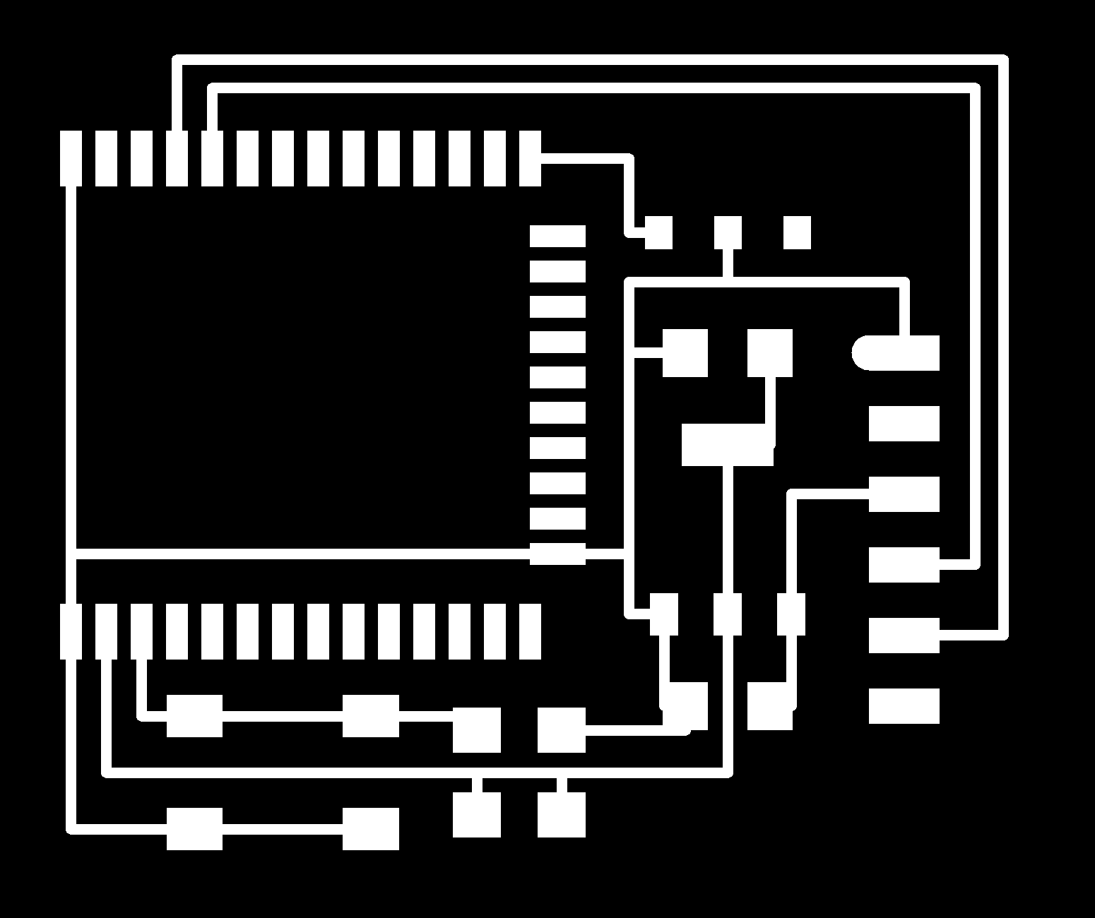
Here is the board that I was based off of: http://academy.cba.mit.edu/classes/networking_communications/ESP32/hello.ESP32-WROOM.png
http://academy.cba.mit.edu/classes/networking_communications/ESP32/hello.ESP32-WROOM.png
For this one, the ESP32 is a microcontroller, and there is only one port to connect to the computer.
Get the six pin version of this: http://academy.cba.mit.edu/classes/embedded_programming/FTDI/USB-FT230XS-UPDI to have my own USB to serial adapter (FTDI cable), or use http://fabacademy.org/2020/labs/ulb/students/quentin-bolsee/projects/samd11c_uart-updi/. I can also buy one at https://www.amazon.com/Converter-Terminated-Galileo-BeagleBone-Minnowboard/dp/B06ZYPLFNB/ref=sr_1_7?crid=3PW3NREIEZM71&keywords=ftdi+usb+to+serial&qid=1669059436&sprefix=ftdi+%2Caps%2C67&sr=8-7
I milled this: http://academy.cba.mit.edu/classes/networking_communications/ESP32/hello.ESP32-WROOM.png
http://academy.cba.mit.edu/classes/networking_communications/ESP32/hello.ESP32-WROOM.traces.png and http://academy.cba.mit.edu/classes/networking_communications/ESP32/hello.ESP32-WROOM.interior.png.
It was really annoying; I milled it like three times and it didn't work. It ended up being because some of the endmills were broken/people put them back in the wrong container for some reason? (I switched them out multiple times but it still ended in disaster); I talked to Shah and he brought some new ones.

Then, I soldered.
Then, I followed this tutorial to connect it to the Arduino IDE. https://circuitdigest.com/microcontroller-projects/programming-esp32-with-arduino-ide.
I followed this to add the boards: https://randomnerdtutorials.com/installing-the-esp32-board-in-arduino-ide-windows-instructions/.
I don't need to program it since it can already connect to Arduino. I added this URL to additional board manager: https://raw.githubusercontent.com/espressif/arduino-esp32/gh-pages/package_esp32_index.json. Then I went to tools -> port -> boards manager and installed ESP32.
I tried connecting the board (the black line on the FTDI connection is on ground) but it didn't recognize it.
I milled another one. Mods said that it cannot open socket; I went to the archshops tutorial and it helped me debug (http://archshops.mit.edu/modela.php).
I followed this guy's tips for the ESP32: https://fabacademy.org/2020/labs/kannai/students/tatsuro-homma/project/ESP32_E_02_Setup_ArduinoIDE.html. I tried selecting WROOM as well as WROVER.
ESP32 with accelerometer
At this point I was very sad but I realized I have to design a board too, even though the board that I didn't design doesn't even work. So I opened Eagle and decided to make a breakout board for the ESP32 module so that I can hopefully fucking connect whatever to it and I don't have to keep making these fucking PCBs that don't work because I can't solder. lol. Then I apologized to Shah for asking him so many dumb questions and he said it was fine because it is his job and also 90% of the time he can't even answer my questions.
This guy also used ESP32 but he bought a breakout board. http://fab.cba.mit.edu/classes/863.19/EECS/people/bibekpandit/week9.html
I followed this tutorial: https://www.pcbway.com/blog/PCB_Design_Tutorial/How_to_make_your_own_ESP32_breakout_board_with_minimal_circuit.html
I turned the grid on and added the ESP32. It is not in the fab library but I found it. I found it from this random library on reddit so I hope it's correct (it's probably not since it's from four. years ago. ) https://github.com/jsmillie7/ESP32-WROOM.lbr.
This guy also used ESP32. http://fab.cba.mit.edu/classes/863.19/Harvard/people/mschrage/11/
For the breakout board, 6x1 pin connector is pretty standard (2.54 mm between the feet).

I also added a button.
Okay the ESP32 that I found on Reddit seems slightly suspicious so I found a more legit one. https://www.snapeda.com/parts/ESP32-WROOM-32E%20(16MB)/Espressif%20Systems/view-part/. I had to sign up for snapeda.com, which I am not sure whether it is a scam or not. Either way, I don't care. As long as the footprint is correct.
This guy came over and complimented my soldering, which was very nice because it did not look that good.
Step 1.
I added VDD, Ground, Enable, and Io0. I used the tactile switch; I found that the opposite sides of the tactile switch are shorted.
Arduino
I added the ESP library to Arduino following this: https://randomnerdtutorials.com/installing-the-esp32-board-in-arduino-ide-windows-instructions/.


Then made the top button switch to program and clicked the reset button. I let the board be ESP32 WroverModule. I opened the serial monitor and switched it to 115200 baud (this is the frequency that the ESP32 communicates at).
The boilerplate code did not compile. We tried Neil's code. It also didn't work, giving us a serial error. We realized that the ESP library is in Python so we need to run pip3 install python. So I need to have Python on my computer to run the ESP code. I ran
pip3 install pyserial
to get serial to work.
Now it says "failed to connect to ESP32. Timed out waiting for packet header."
Flip the switch, and then click the RESET button.
I used this code:
I tried my other board and it seemed to work?? ???????????? I have to click the RESET button and then uplaod the program (and make sure the switch is on program mode.) It says this, but I looked it up and it's probably fine.
https://www.turais.de/esp8266-hard-resetting-via-rts-pin/
The message: hard resetting via rts pin... is not an error message. Just an indication whats going on
Then I added this library https://github.com/T-vK/ESP32-BLE-Keyboard.
Make sure you can use the ESP32 with the Arduino IDE. Instructions can be found here.) Download the latest release of this library from the release page. In the Arduino IDE go to "Sketch" -> "Include Library" -> "Add .ZIP Library..." and select the file you just downloaded. You can now go to "File" -> "Examples" -> "ESP32 BLE Keyboard" and select any of the examples to get started.
I uploaded the example SendKeyStrokes by flipping the switch to program, pressing RESET, and clicking upload. Then I ran the program by flipping the switch again and pressing RESET again.
It worked! The program types hello world, hits enter, and then scrolls.
Networking: Bluetooth
I made an ESP32 board (http://academy.cba.mit.edu/classes/networking_communications/ESP32/hello.ESP32-WROOM.png) that connects to the iPad via Bluetooth and types hello world.
ESP32 Breakout Board + Swipe Left/Right
For this next part I used the ESP32 breakout board, documented in the final project page. I connected to my iPad using Bluetooth, using the ESP32, and I would like to use bleKeyboard (https://github.com/T-vK/ESP32-BLE-Keyboard) to swipe left or right to turn the pages on my iPad.
Programming in Arduino
I already had an ESP32 board that worked with the archshop computers, but now I want it to work on my Mac. First, I installed BLE onto my computer, using their instructions:
Installation (Make sure you can use the ESP32 with the Arduino IDE. Instructions can be found here.) Download the latest release of this library from the release page. In the Arduino IDE go to "Sketch" -> "Include Library" -> "Add .ZIP Library..." and select the file you just downloaded. You can now go to "File" -> "Examples" -> "ESP32 BLE Keyboard" and select any of the examples to get started.
Anthony helped me find documentation for Keyboard in Arduino, so I know which keys I am able to press (bleKeyboard has these keys as well as several more specific to bleKeyboard): https://www.arduino.cc/reference/en/language/functions/usb/keyboard/keyboardmodifiers/
Then, I tried to program it to turn pages. I had a lot of trouble figuring out which key to press to do so, and I tried a bunch such as KEY_PAGE_UP/DOWN, KEY_LEFT_ARROW/RIGHT_ARROW, and the back page in bleKeyboard, as well as trying to use bleMouse (https://github.com/T-vK/ESP32-BLE-Mouse). None of these worked. Also it kept connecting to my computer via Bluetooth rather than my iPad and I couldn't type because it kept trying to scroll left and right. Eventually I figured it out though.
After a lot of trouble trying different keys, I followed this guy's sketch: https://www.reddit.com/r/esp32/comments/mniscy/esp32_bluetooth_page_turner_the_enclosure_is_made/
It works by pressing the right arrow key for some amount of time, then releasing the key.
bleKeyboard.press(KEY_RIGHT_ARROW);
delay(50);
bleKeyboard.releaseAll();

/**
 * This example turns the ESP32 into a Bluetooth LE keyboard that swipes right
 */
#include <BleKeyboard.h>

BleKeyboard bleKeyboard;

void setup() {
  Serial.begin(115200);
  Serial.println("Starting BLE work!");
  bleKeyboard.begin();
}

void loop() {
  if(bleKeyboard.isConnected()) {
    Serial.println("right arrow!");
    bleKeyboard.press(KEY_RIGHT_ARROW);
    delay(100);
    bleKeyboard.releaseAll();
  }
  Serial.println("Waiting 5 seconds...");
  delay(5000);
}
Distance Sensing + Vibration
Then, for testing purposes, I combined this code with the code for the vibration motor on IO14. I wrote code to make it simultaneously work as a metronome and turn the page when distance is above or below certain cutoff values.
//distance sensor
#include "Adafruit_VL53L0X.h"
//bluetooth keyboard
#include <BleKeyboard.h>
#define ledPin 14  // The pin the LED is connected to

//int bpm = 72;

Adafruit_VL53L0X lox = Adafruit_VL53L0X();
BleKeyboard bleKeyboard;

void setup() {
  Serial.begin(115200);

  // wait until serial port opens for native USB devices
  while (! Serial) {
    delay(1);
  }

  Serial.println("Adafruit VL53L0X test");
  if (!lox.begin()) {
    Serial.println(F("Failed to boot VL53L0X"));
    while(1);
  }
  // power
  Serial.println(F("VL53L0X API Simple Ranging example\n\n"));
  Serial.println("Starting BLE work!");
  bleKeyboard.begin();

  pinMode(ledPin, OUTPUT); // Declare the LED as an output
}


void loop() {
  VL53L0X_RangingMeasurementData_t measure;


  if (bleKeyboard.isConnected()) {
    // hold and release right arrow key to swipe forward
    Serial.print("Reading a measurement... ");
    lox.rangingTest(&measure, false); // pass in 'true' to get debug data printout!

    if (measure.RangeStatus != 4) {  // phase failures have incorrect data
      Serial.print("Distance (mm): "); Serial.println(measure.RangeMilliMeter);
      if (measure.RangeMilliMeter <= 40) {
        Serial.println("left arrow!");
        bleKeyboard.press(KEY_LEFT_ARROW);
        delay(100);
        bleKeyboard.releaseAll();
        digitalWrite (ledPin, HIGH);  // turn on the LED
        delay(100);
        digitalWrite (ledPin, LOW); // turn off the LED
      }
    } else {
      Serial.println(" out of range ");
      Serial.println("right arrow!");
      bleKeyboard.press(KEY_RIGHT_ARROW);
      delay(100);
      bleKeyboard.releaseAll();
      digitalWrite (ledPin, HIGH);  // turn on the LED
      delay(100);
      digitalWrite (ledPin, LOW); // turn off the LED
    }
  }

  delay(500);
}
I also wrote another version that instead pulsed the vibration motor once when I tilted my head left and twice when I tilted my head right, so I didn't need to keep looking at my iPad/connecting to Bluetooth while testing the cutoff values for the distance sensor.