Design
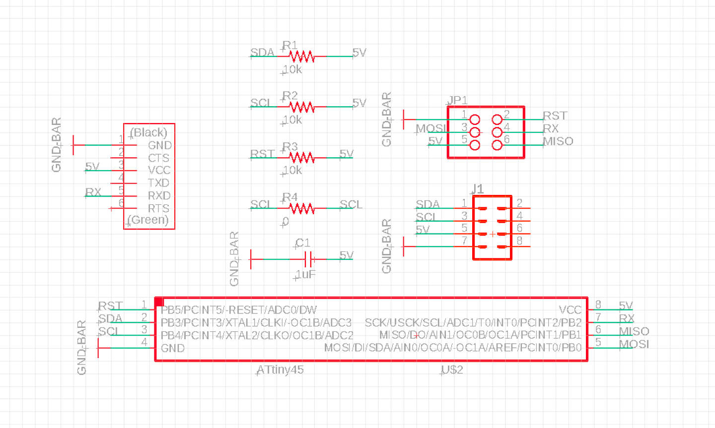
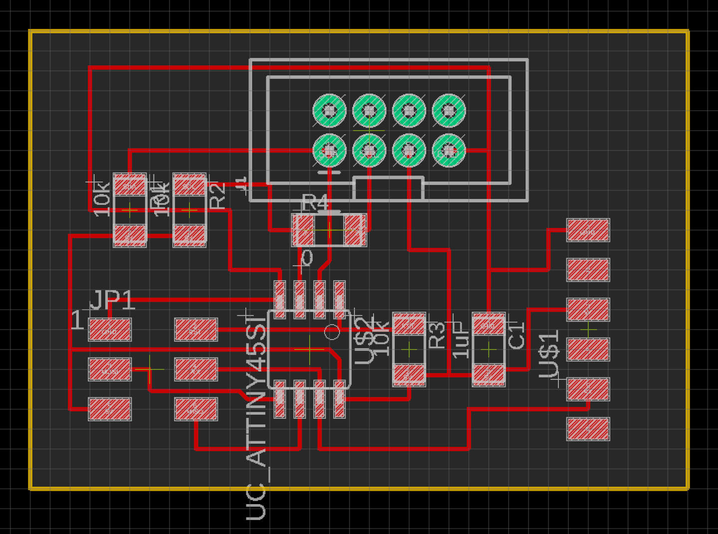
For this week, I wanted to try to make and use an OLED display, the SSD1306. The board design and components were already on the HTMAA website, which are pictured below.
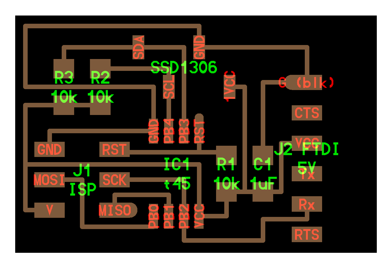
Later, I changed the design via EAGLE when I realized that the architecture shop OLED device had a different ordering, and it became too messy and unreliable to solder everything on.
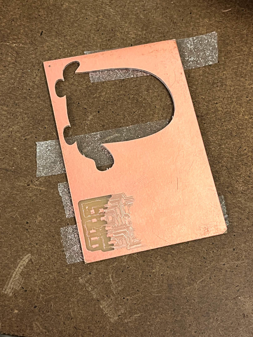
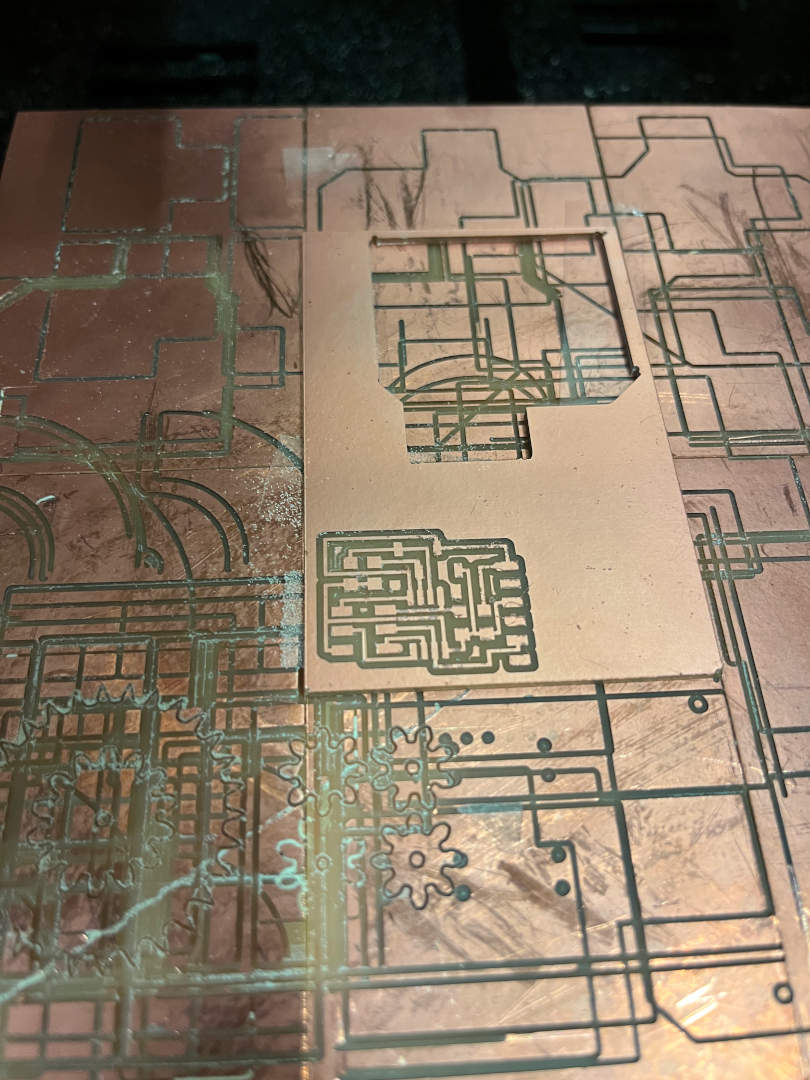
Mill
I used the Roland SRM-20 to mill the board using the given traces and outline PNGs. I ran into some milling issues because the 1/64 endmill was not properly cutting for some reason (see below). I replaced the endmill and got it to work! Since I already made a bunch of boards in the past few electronic weeks, it felt good to do everything smoothly and quickly.
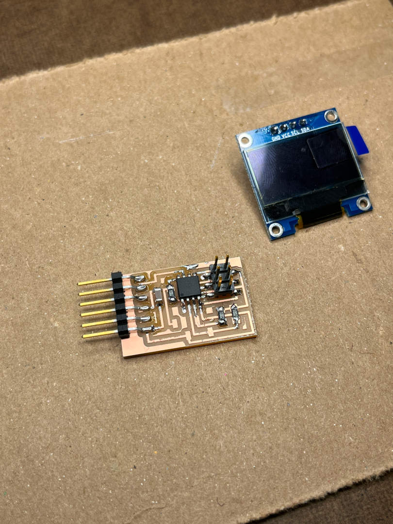
Solder
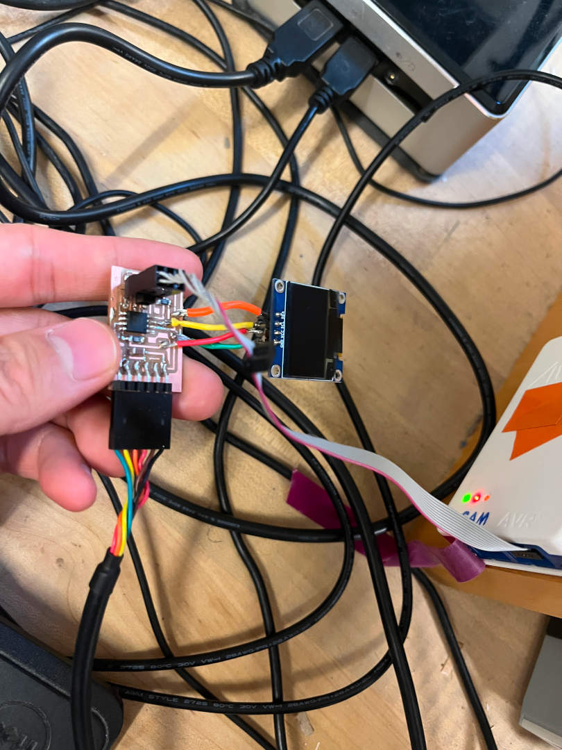
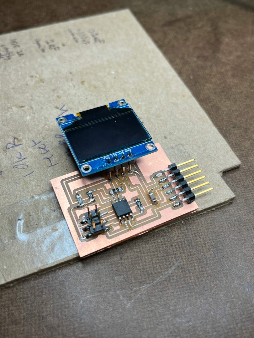
Just like before, I located and soldered on all of the necessary parts. The only part I had trouble finding was the FTDI because I only saw one drawer with FTDIs with 36 pins. I thought I was clever to try to snap the 36 pins to create one smaller part with 6 pins, but then I realized that was exactly what you were supposed to do! The OLEDs in the architecture shop actually have the VCC and GND ports reversed, so I tried to fix it by using jumper wires to connect the pins to the right joints. It took quite a while because the process was very messy.
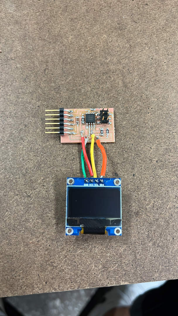
Program
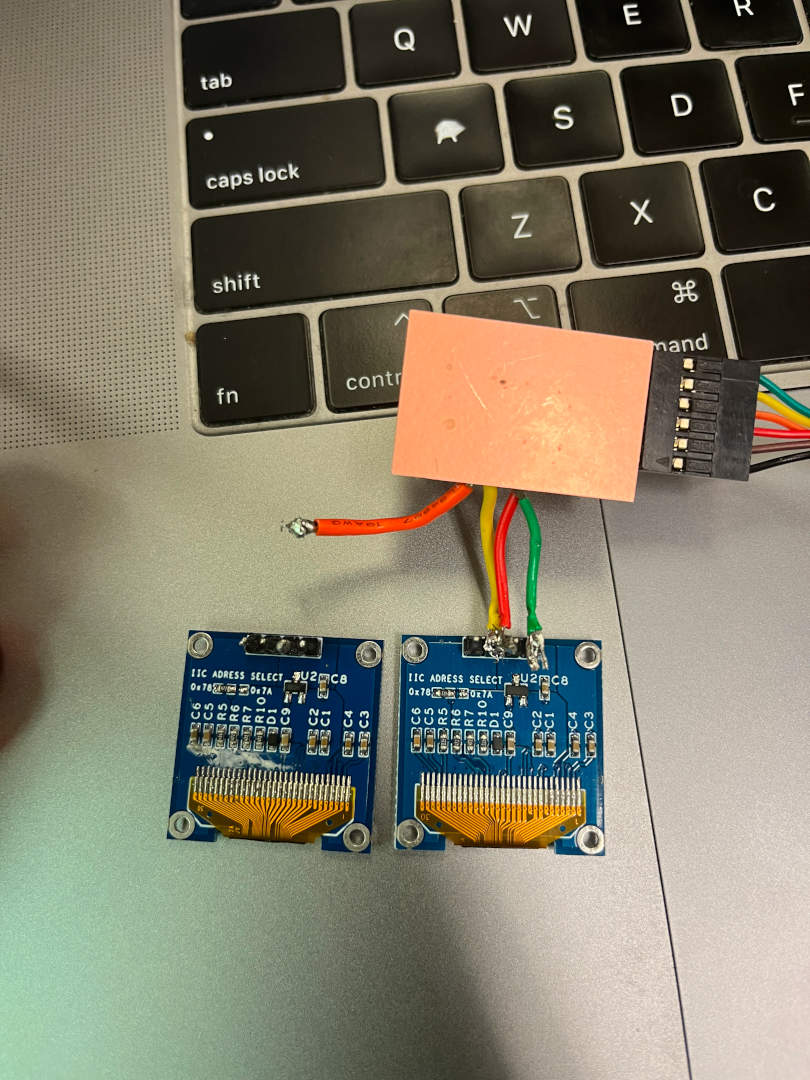
Programming the board became a struggle because while the program successfully loaded onto the board, the screen was not working. With the help of the TAs, we first thought that the screen was bad with some white-looking "mold" (see picture below), so that would be the fix. It took a while to unsolder the old screen and solder on the new one, but when I finished and tested it, it still didn't work! We then believed that the jumper wires were quite unreliable (you can see how unstable it is in the picture), especially with trying to use solder to connect the wire to the screen directly.
This prompted me to redesign the schematic to use a different part that would be more reliable.
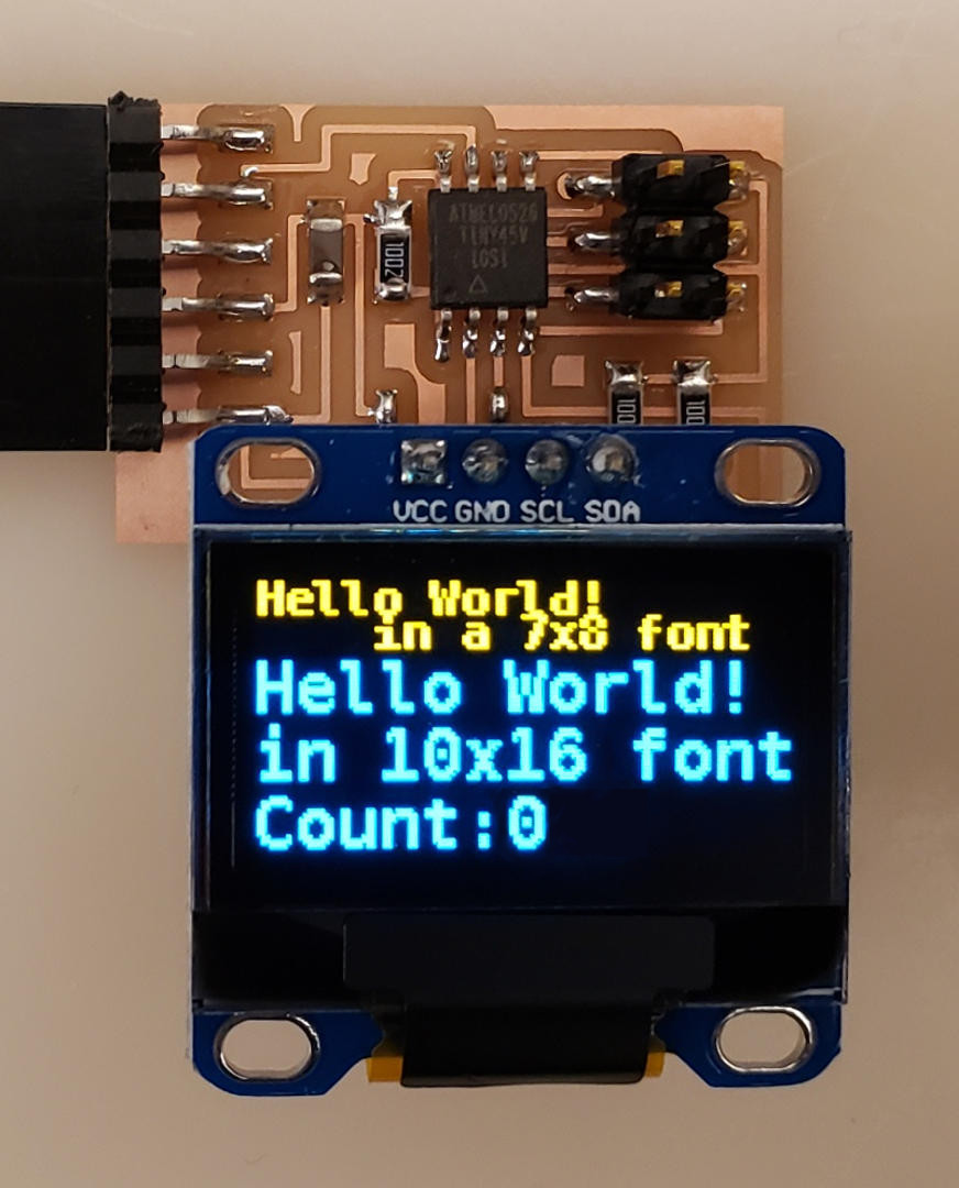
After going through the milling and soldering process again, I realized that I chose the wrong part in EAGLE because the physical part wouldn't fit on the board! I decided to improvise and just directly solder the screen onto the board.
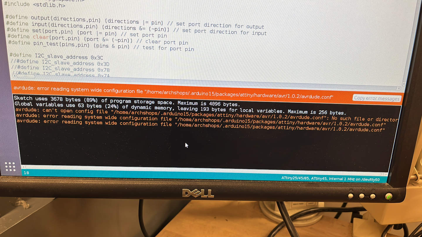
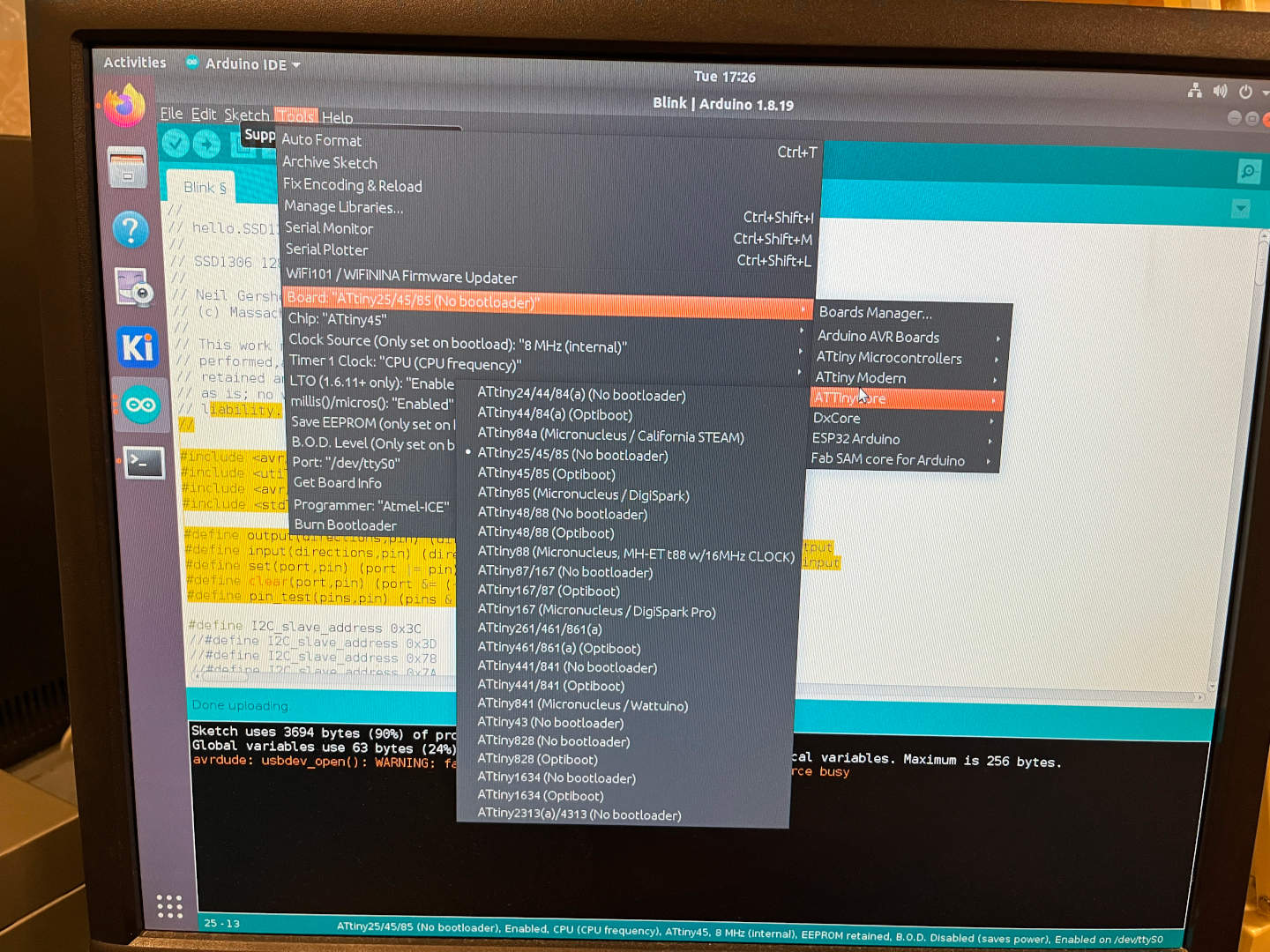
Programming the board initially didn't work because I had actualy chosen the wrong board configuration. There's the ATtiny Microcontroller that you can select the "ATtiny25/45/85" from and the ATTinyCore that you can select either the "ATtiny45/85 (Optiboot)" or "ATtiny25/45/85 (No bootloader)". Turns out, we want to select the "ATtiny25/45/85 (No bootloader)" option! Using the C code on the HTMAA website, we finally get the screen working :).