In-Circuit Programmer
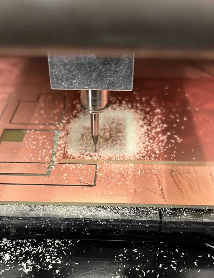
Milling the board
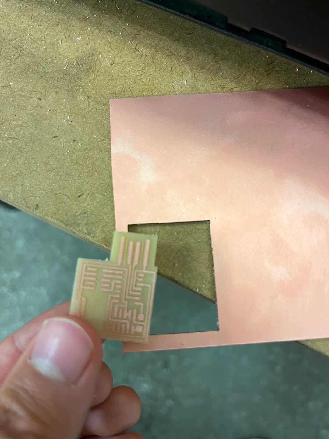
First, I used the Modela MDX-20 3D Milling Machine to create the circuit board. The traces were cut using a 1/64 inch end mill, and the chip was cut out using a 1/32 inch end mill. I tried to align the end mill as close to the corner as possible, but I still missed by a centimeter.
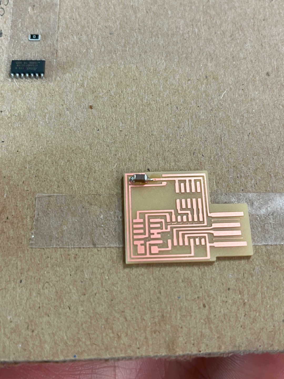
Soldering
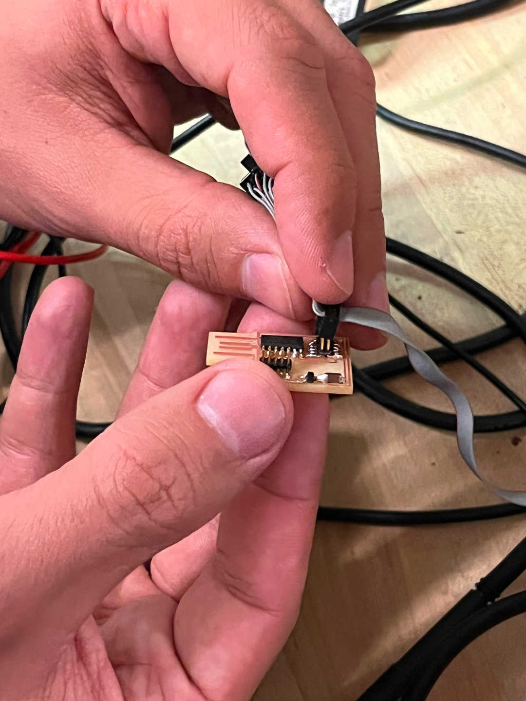
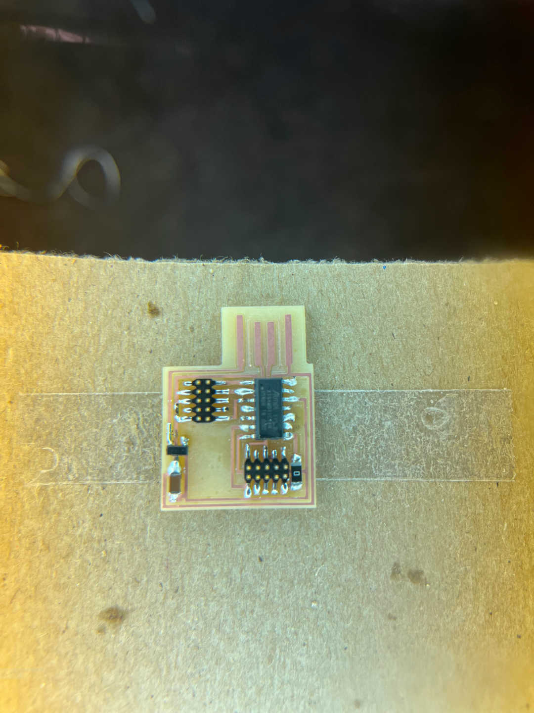
Next, I soldered the parts onto the board. I've never soldered anything before, so I first grabbed a used copper plate and tried soldering on a random part just to get some practice and see what would happen (I may or may not have accidentally burned my hand). Once I felt ready, I soldered onto the actual chip, which roughly took an hour to do. I learned a few tricks to speed up the process while doing it: the rosin braid to desolder and pre-heating the plate/part connection with the soldering iron before tapping solder onto it. If you look closely, you'll see that the micro-controller solder is very fat while the headers are not when I learned the latter trick.
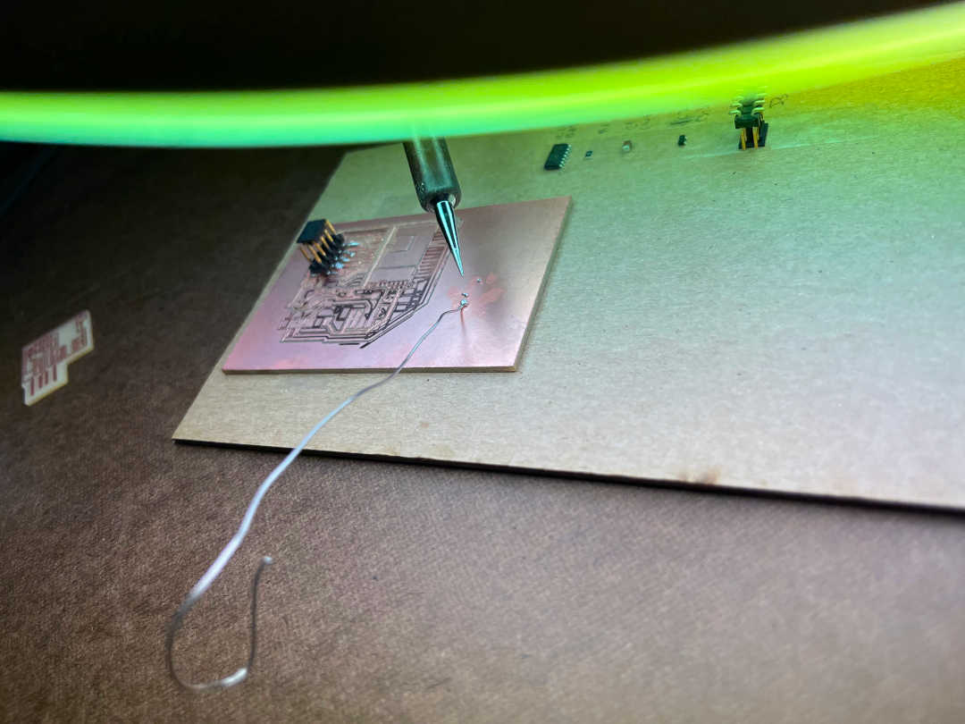
Programming
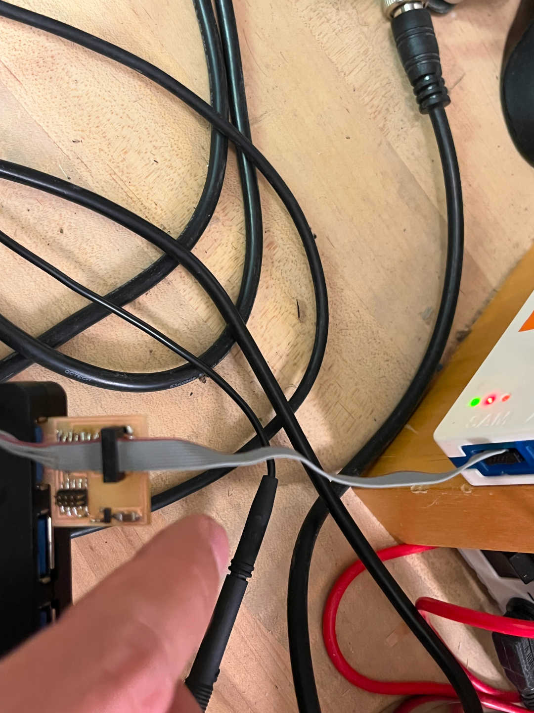
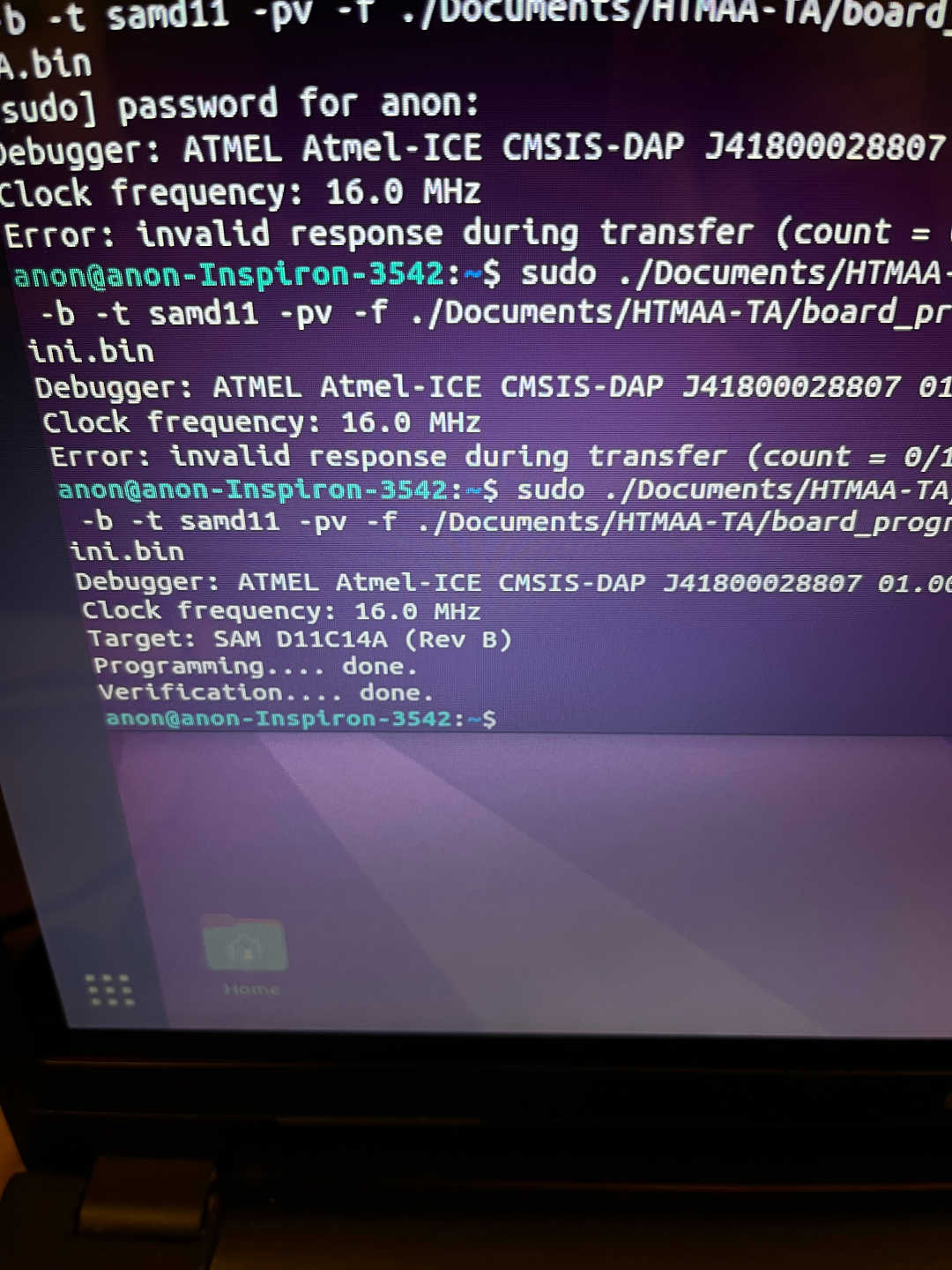
Finally, I programmed the board! If you look at the second picture, the light actually sometimes wasn't turning green because the USB connection wasn't stable. The chip would jiggle around since it was loose, causing the connection to sometimes sever. With the right angle, I was able to program the chip :).