Design
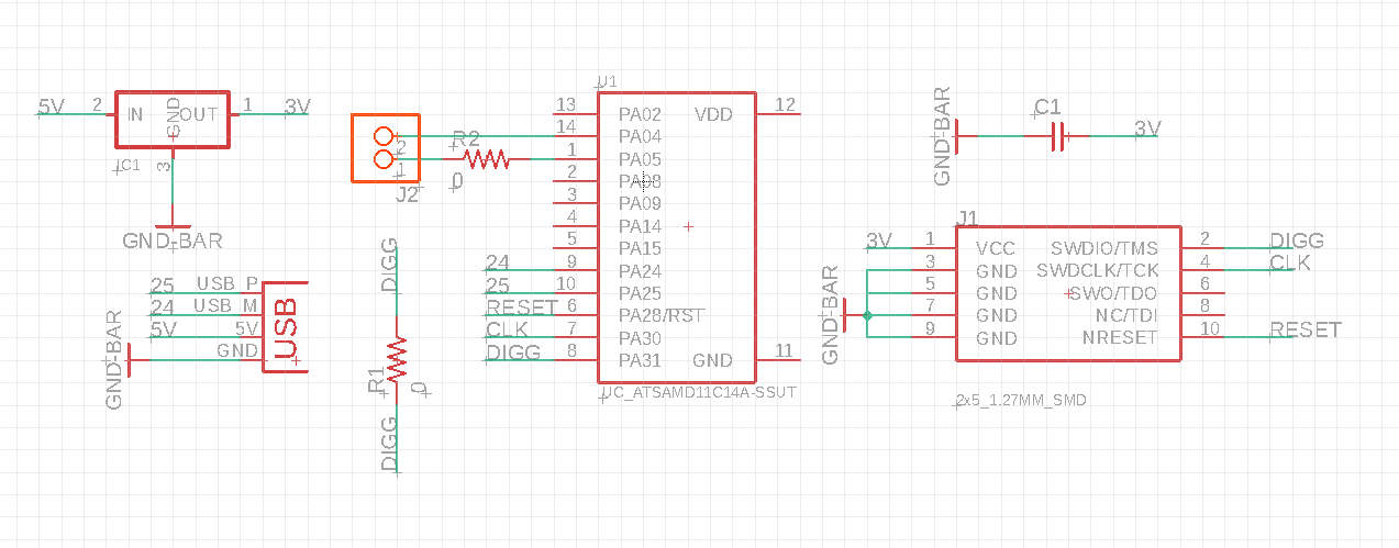
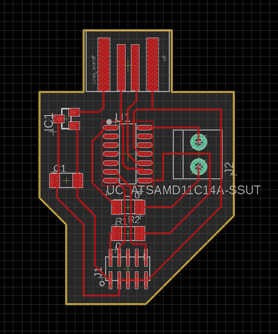
I decided to try to use a piezo disc transducer! I figured that the board design should be the exact same as in previous weeks with the SAMD11C14, except instead of connecting a button and LED to the microcontroler on the digital pins, we connect a piezo disc transducer to the analog pins via a two port terminal head. The actual design is quite straightforward since I already got some practice from the previous weeks! We have the schematic and PCB below:
Mill
Next, I used the Roland SRM-20 to mill the board. I usually use the older version, the MDX-20, but it seemed to be out of operation on the day I used it (i.e. kept giving me a permission denied error, and I tried to follow the archshops tutorial to fix it to no sucess). One funny thing that happened was that the board started flying out because the tape somehow came off, so the endpoint ended up moving the board. I didn't catch it on camera, but I fixed it by replacing the tape and re-running the mill.

Solder
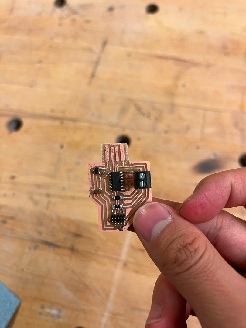
Thankfully, after having several weeks of practicing, soldering was quite straightforward too. The only new thing I learned was to solder the terminal block on because it's a vertical part with pins that point straight down. Therefore, to solder it, I had the surround the end on the copper (i.e. it's a circle - reference the PCB design). It wasn't difficult to do at all because the heat transfer almost made the circular motion automatic.


Program
First, I realized that my USB was way too fat, so it wouldn't fit into any USB ports! My friend also told me that the copper on the edges of the USB might short circuit the board. I used a metal scraper to slowly scrape away the edges of the USB and a knife to pry away the copper sides of the USB.

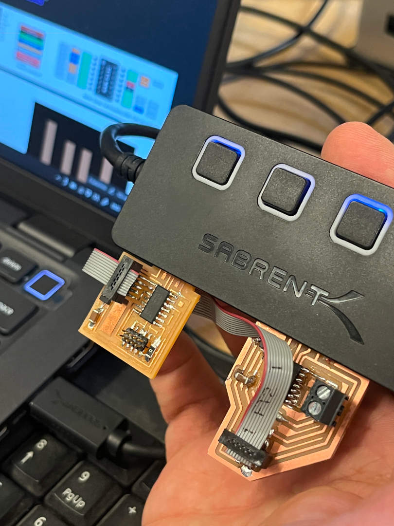
When I tried to add a bootloader to the board, it gave me classic "invalid response during transfer (count = 0/1, status = 0)" error. Of the many tries to bootload the board, only once worked when using one of the TA's programmer boards (see first pic below). After looking at it many times with the TAs, we first thought that the problem might have been mis-soldered joints, so I did a continuity test on all of the joints with a multi-meter. But it was fine! After a while, we realized what the problem was: I completely forgot to make a connection from the microcontroller VDD pin to the 3.3V wire! This meant that although the board would by chance get bootloaded, Arduino would never recognize the board by itself because no power from the USB is reaching the microcontroller. I added a jumper wire to make the connection.

With that fixed, I added the piezo transducer sensor to the terminal block and tested the sensor to make sure that it worked with the code below!
                int sensorPin = 4;

                void setup() {
                // put your setup code here, to run once:

                }

                void loop() {
                // put your main code here, to run repeatedly:
                int reading = analogRead(sensorPin);
                Serial.print("Value: ");
                Serial.println(reading);
                delay(200);
                }