How To Make (Almost) Anything Neil Gershenfeld
MCKENZIE ROSS HUMANN
MIT Department of Urban Studies and Planning
3D PRINTING AND SCANNING
10.05.22
group assignment:
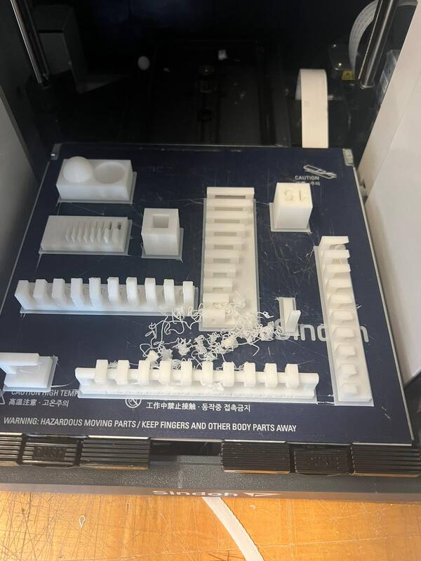
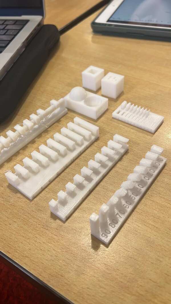
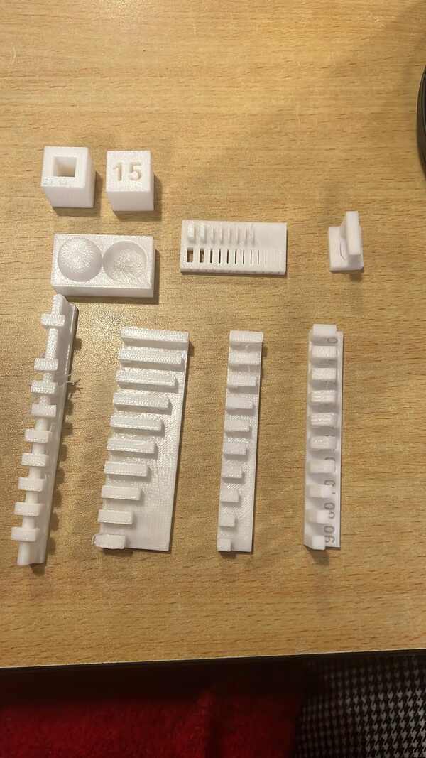
- test the design rules for your 3D printer(s)
individual assignment:
- design and 3D print an object (small, few cm3, limited by printer time)
that could not be made subtractively
- 3D scan an object (and optionally print it)
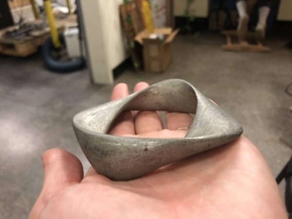
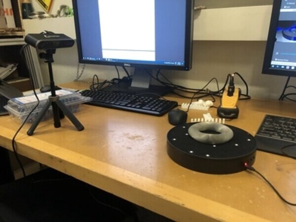
Interesting metal object I found by Jen's desk
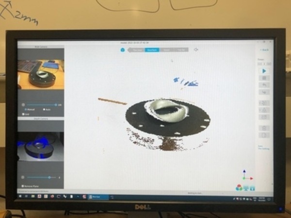
Scanning attempt 1 in progress.
Scanning attempt 1 results.
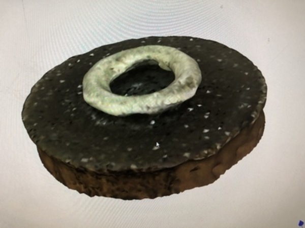
Scanning attempt 1 results.
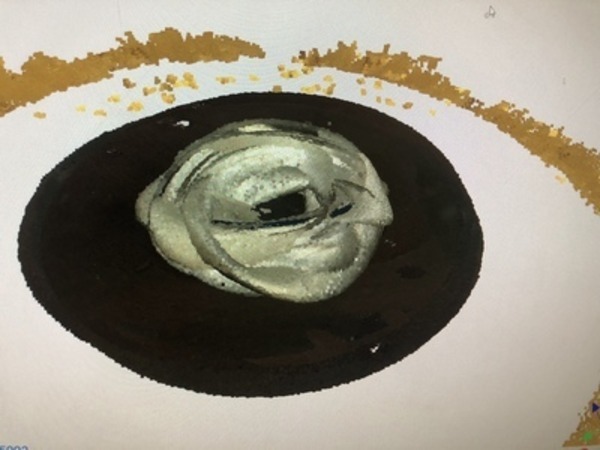
Results of second attempt.
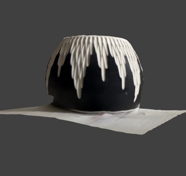
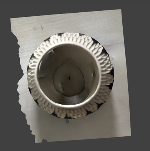
Scan of candle holder using Scaniverse. This side had the most light and scanned the best.
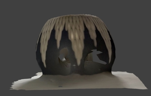
This side had less light and did not scan as well.
The inside parts of the candle holder also did not scan well.
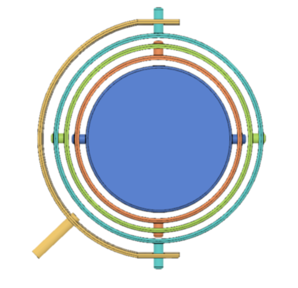
My gyroscope design in Fusion 360.
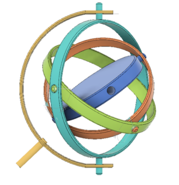
Using the joint functions, I could model how my design would move.
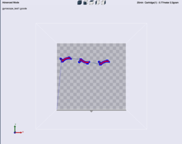
Here I tested three subsections to figure out the right joint size settings.
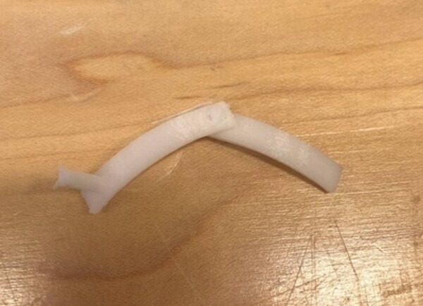
The joint with the greatest space between the pin and the hole easily separated.
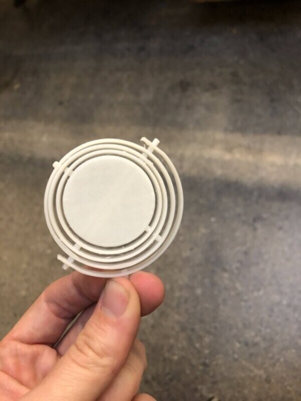
My new (fake) gyroscope.
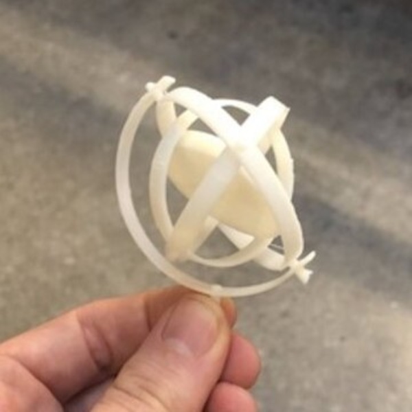
The gyroscope easily moved into this position, however there was some friction still at joints that did not separate cleanly. Since the middle section is rather light there won't be enough momentum to overcome the friction in the joints to create lasting movement.
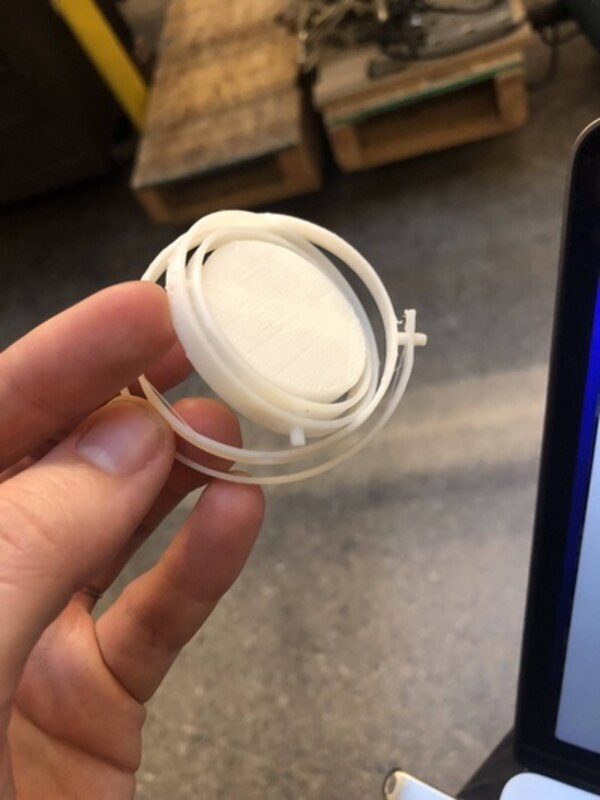
The joint pins were still too short and dislodged a little too easily.