How To Make (Almost) Anything Neil Gershenfeld

MCKENZIE ROSS HUMANN

MIT Department of Urban Studies and Planning


ELECTRONICS DESIGN

10.12.22

group project:
use the test equipment in your lab to observe the operation of a microcontroller circuit board

individual project:
redraw an echo hello-world board, add (at least) a button and LED (with current-limiting resistor) check the design rules, make it, and test that it can communicate

extra credit: simulate its operation


Group Assignment

...to be completed at a later date...


Design a hello-world board with LED & button

To start, I followed Neil's echo hello-world board schematic with the 10-pin programmer and ATSAMD11C microcontroller. I also referenced previous student's work here, here, and here. The basic steps were 1. find parts in Eagle; 2. draw schematic; 3. move parts on the board; 4. route parts. Sounds easy!

My primary challenge was finding the right parts; this is where looking at past student's work was helpful but also confusing. Often the photos of their schematics included the specific part names, but this did not always match what was available in the fab library on Eagle. And then the part names in the lab also do not always match... First, I was not sure which programming pin piece I was supposed to use. I decided to use the "CONN_05x2-PINHEAD-SMD" since this looked like the 10-pin from other work. However, I was confused that my connector piece had pin numbers that were a reflection of the pin numbers shown in another schematic. One of the TAs taught me that the pin numbers are only for reference though. She also mentioned that we should be using the CONN_05x2-ARM-DEBUG connector instead, but when I added this to the schematic the shape was much different than what I was expecting! This confusion led to me spending a lot of time re-connecting the connector piece and switching out the connector piece to the arm-debug connector, only to switch back to the original piece. In the end I used the pinhead-smd connector... which turned out to not be wrong! More on that later.

I initially only designed the original echo hello-world board for extra practice in Eagle. To add the LED and button, I referred to the other student examples for how to connect the button and LED to the microcontroller. Jake's tutorial was also a good source of information. Routing took quite a while and was a real challenge. I mostly practiced routing without following schematics from other people, so when I finally finished I was proud of my work.

When I milled the board, I ran into one problem, where one section of copper remained even though it was not in the png. I think the space that was supposed to be removed was too small for the mill. To fix this, I cut out the piece using a box cutter. The board milled nicely overall though. I also realized that I had used 0 infill, so it removed all the copper within the rectangular png space even though I was going to cut out a smaller shape.

Finding the parts is where the real challenges began. First, the capacitor was much smaller than the space between the pads. I was confused because there was only one unpolarized capacitor option in the Eagle library; so how could I have chosen the wrong piece in the Eagle library? Then I realized there is an additional drop-down menu showing different types of unpolarized capacitors, one of which was labeled 'fab'. Then I realized that the arm-debugger connector piece was the correct piece I should have used; the reason the footprint was much different than what I was expecting was because I had not yet chosen the correct version from this other drop-down menu! I continued to solder up my board and was able to add extra solder to bridge the large gap across the capacitor pads. I also soldered the "CONN_05x2-PINHEAD-SMD" even though we don't have any thing to plug it into for bootloading the microcontroller. But Jen described to me how I can make an additional small board that connects the 'wrong' connector to the arm-debugger. I will have to finish making this board later this week.

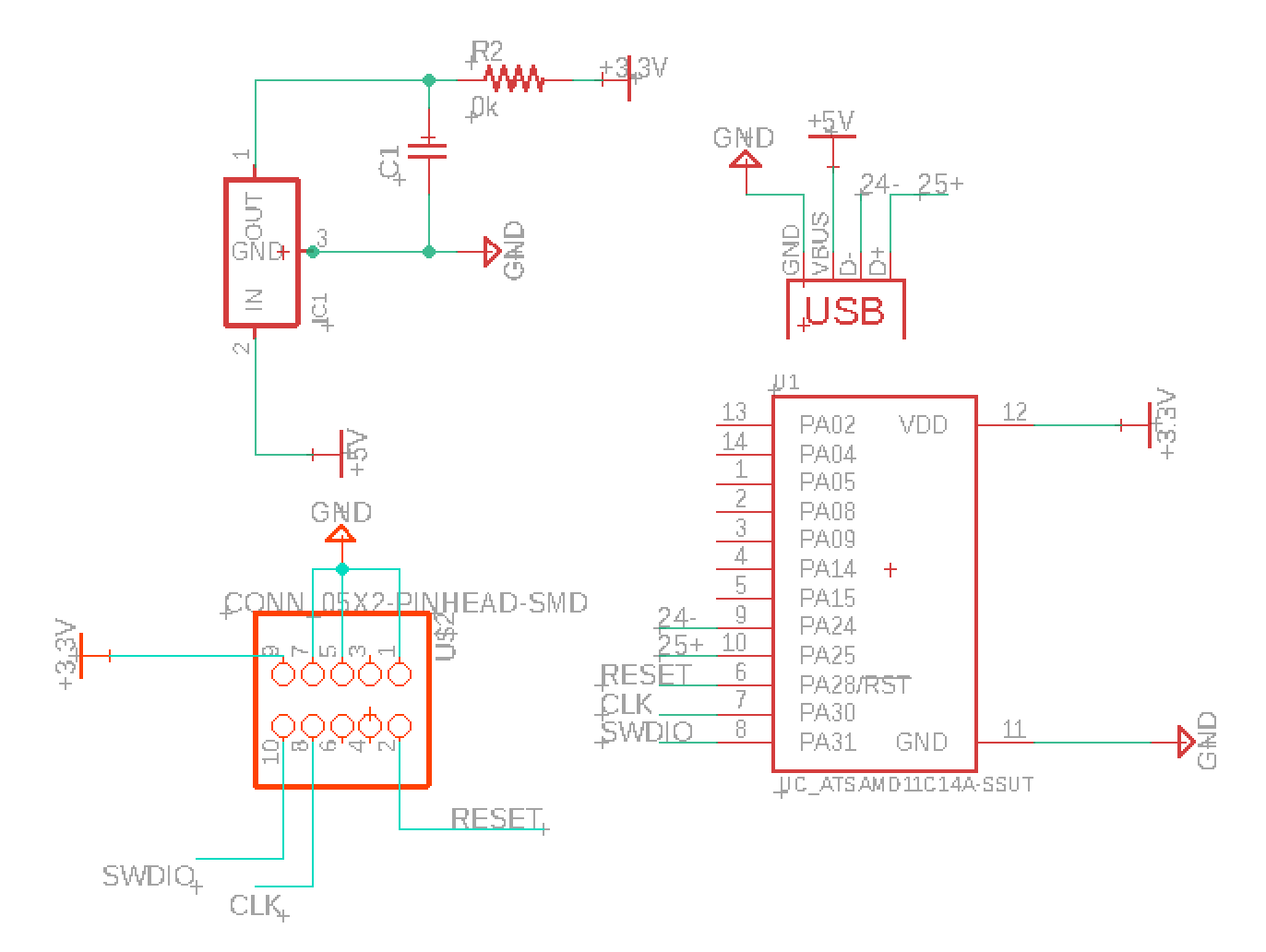
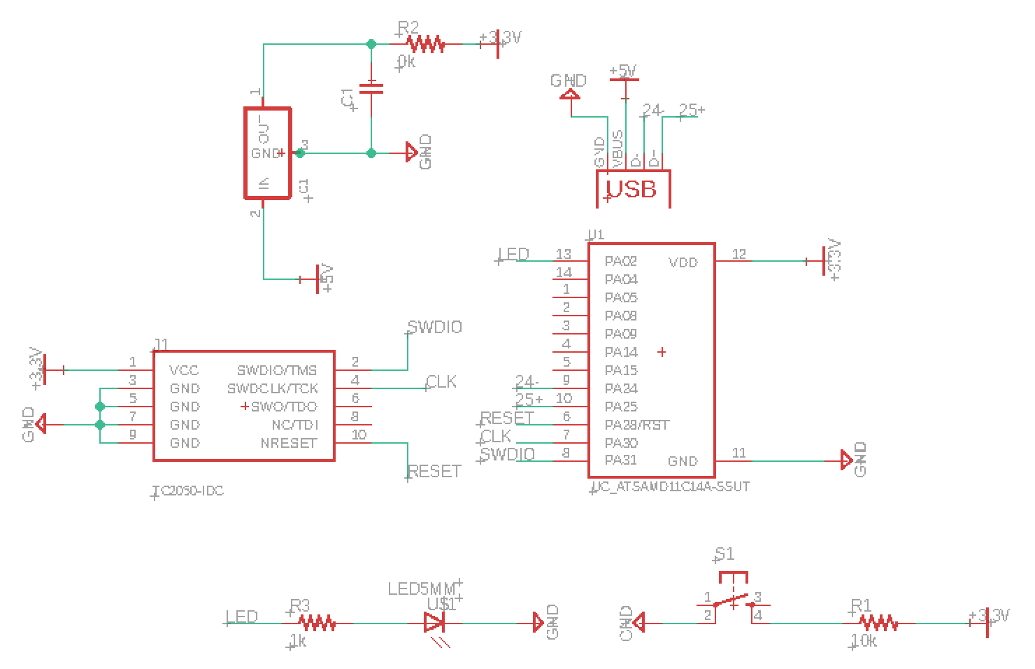
echo hello-world schematic (with wrong/mirrored connections for 10-pin connector)

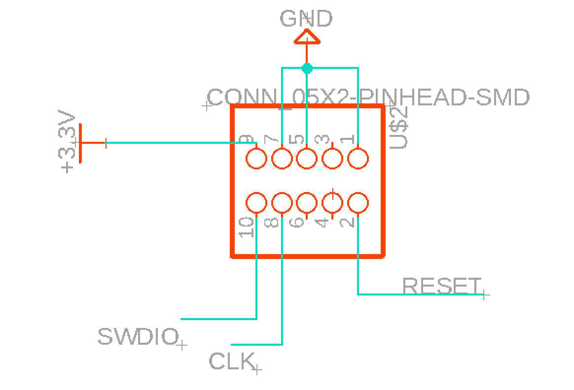
10-pin connector in Eagle

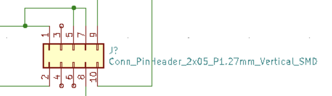
image from another student's work showing 10-pin connector in KiCad. I was confused because the numbers were mirrored in this one compared to in my schematic

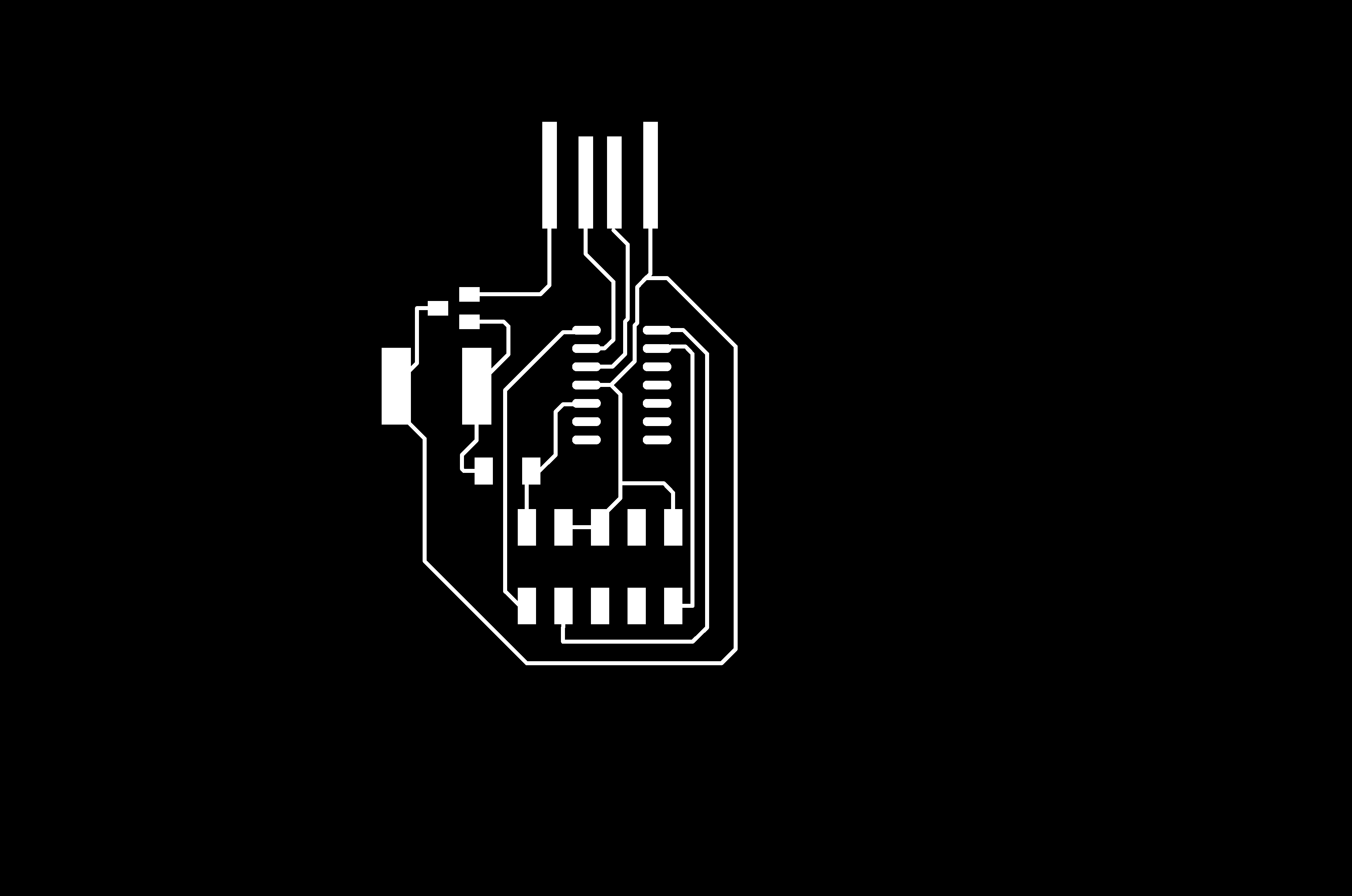
echo hello-world routing (with wrong/mirrored connections for 10-pin connector)

replaced 10-pin smd with arm-debugger connector (before second-guessing myself and going back)

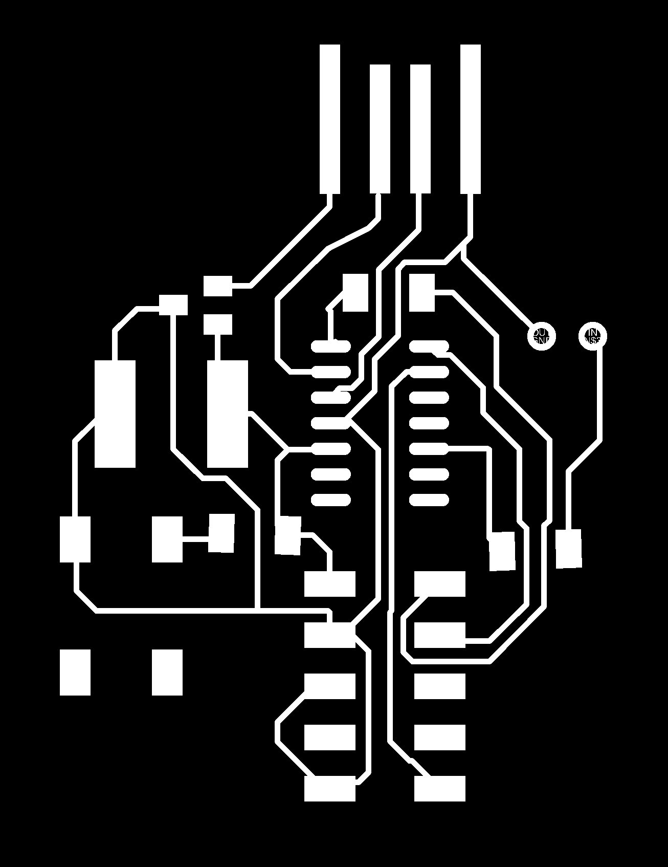
echo hello-world with led and button traces

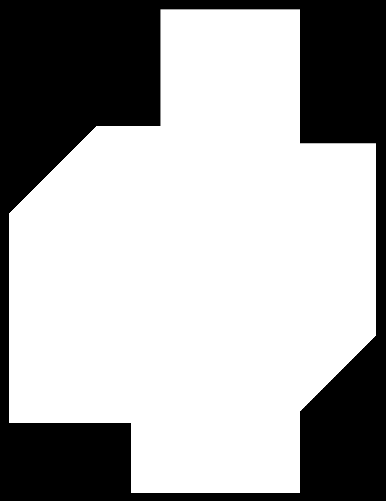
echo hello-world outline

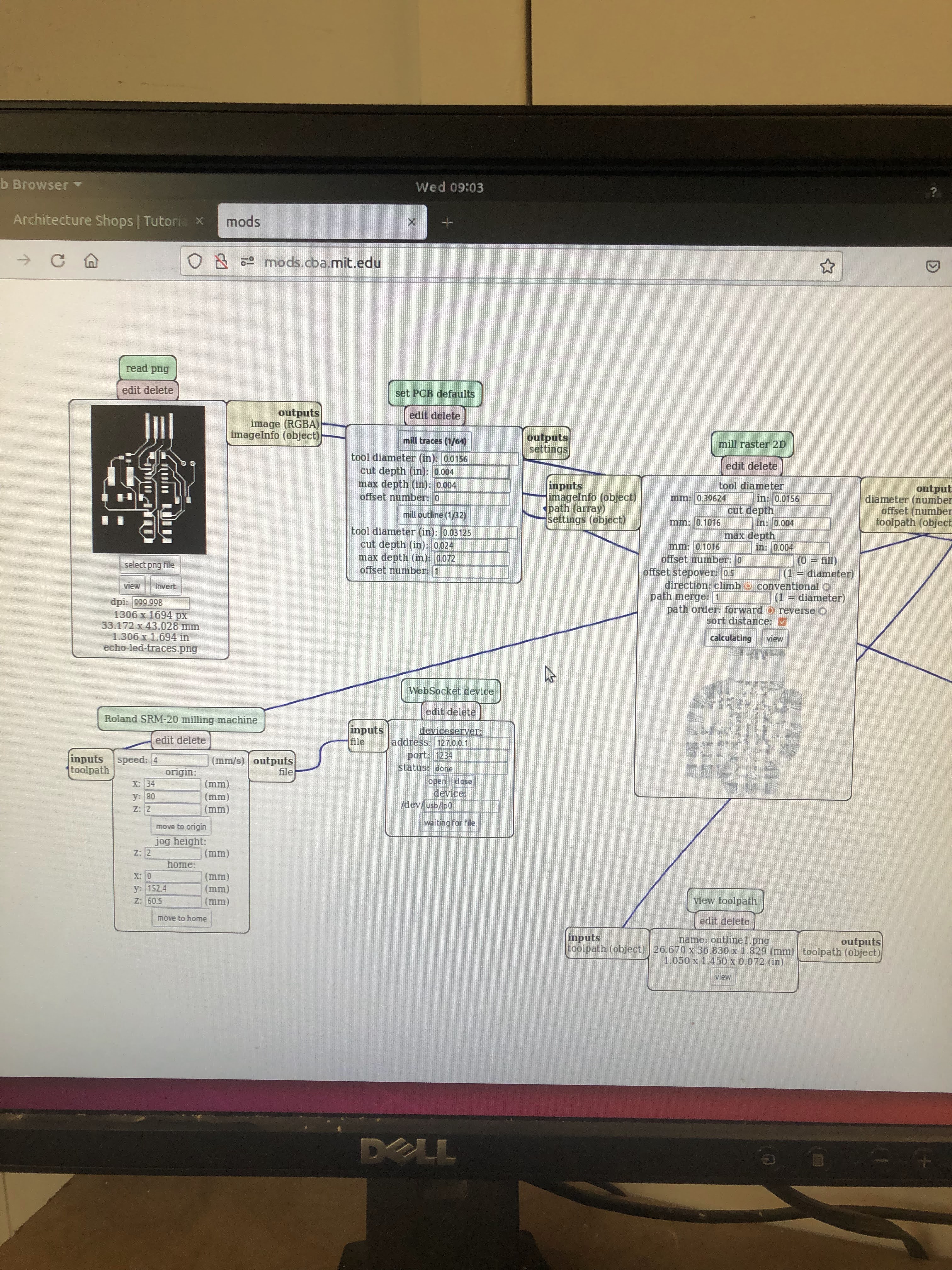
using mods to set up the machine
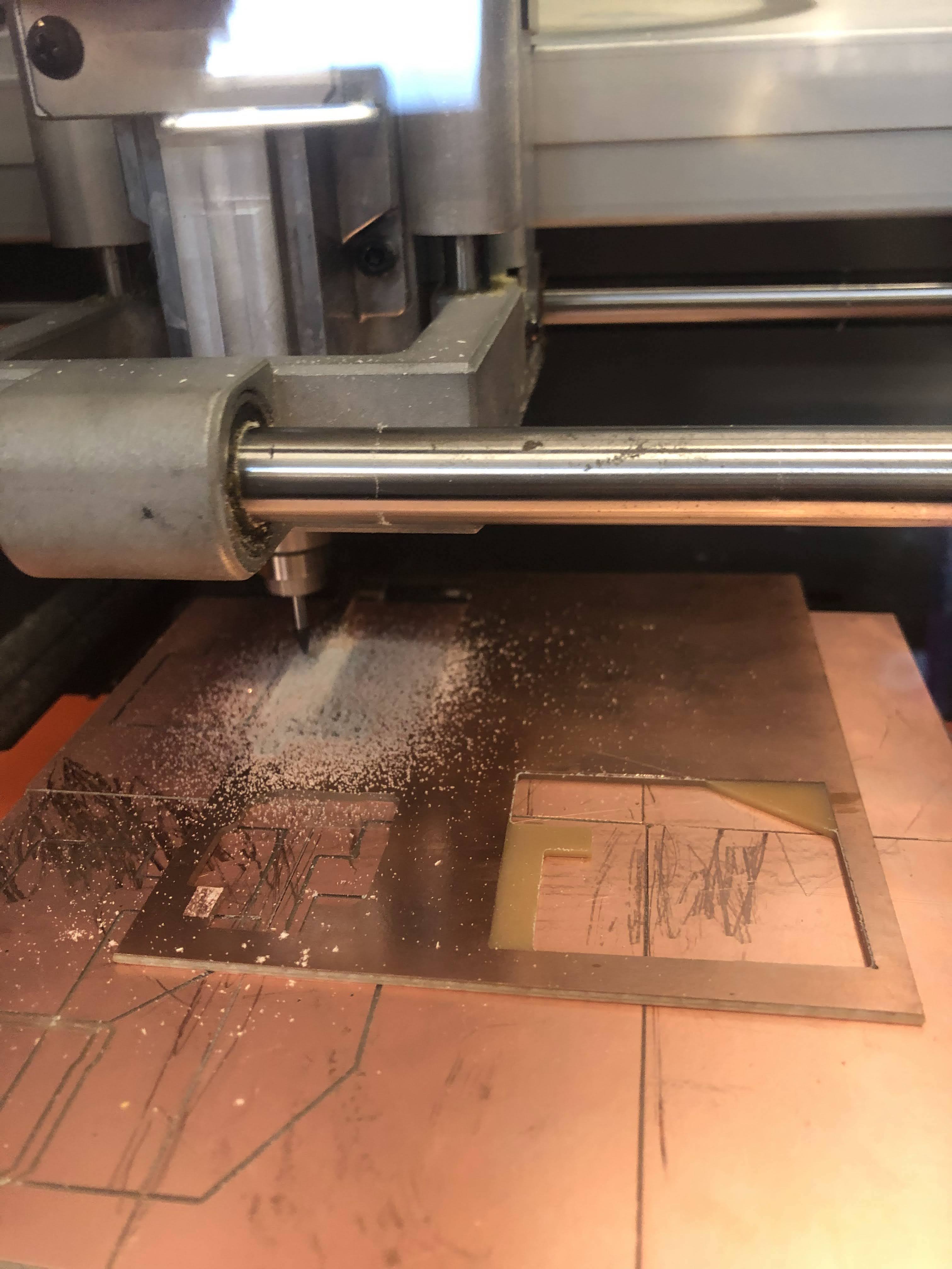
view while milling

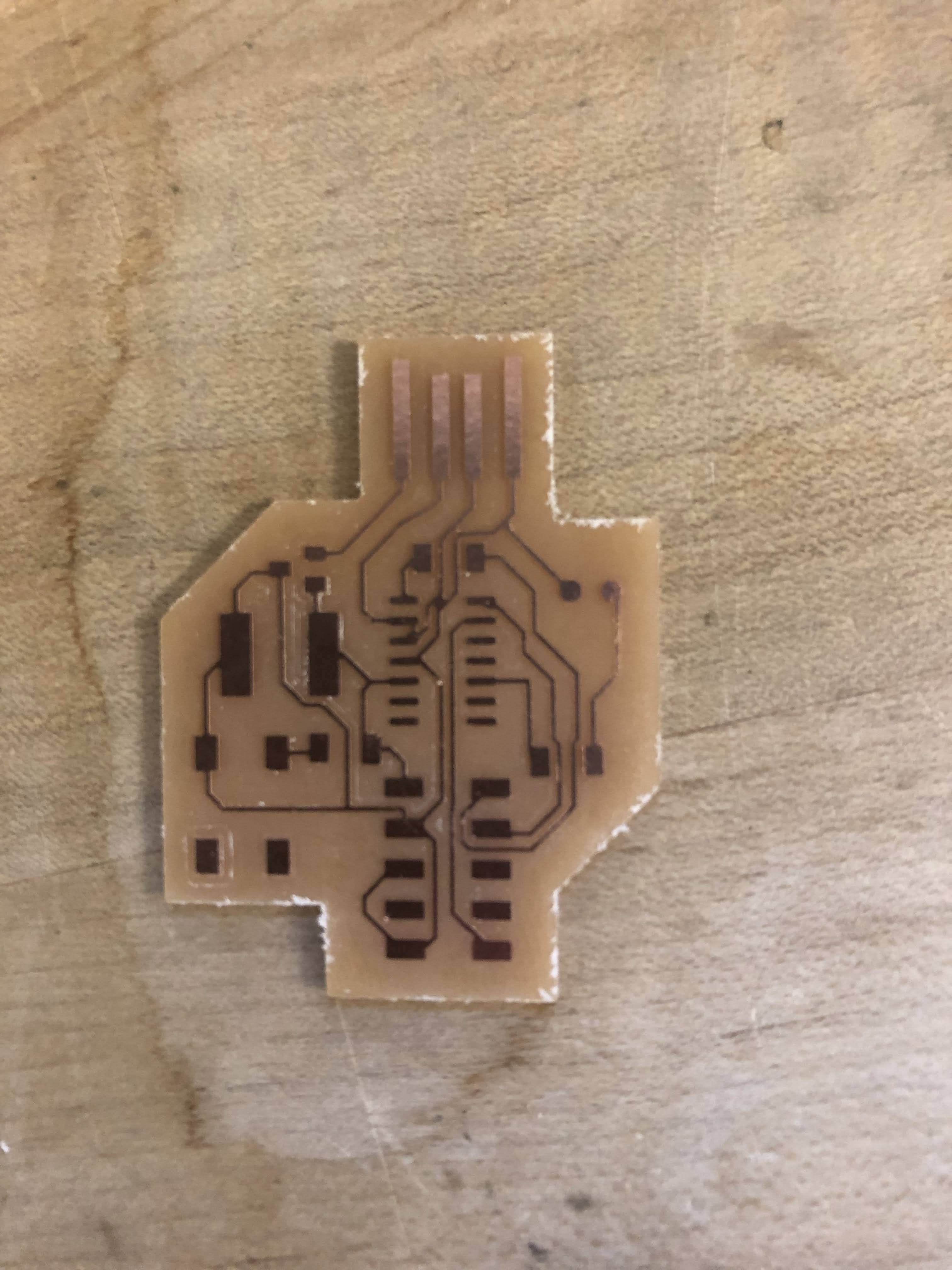
freshly milled board

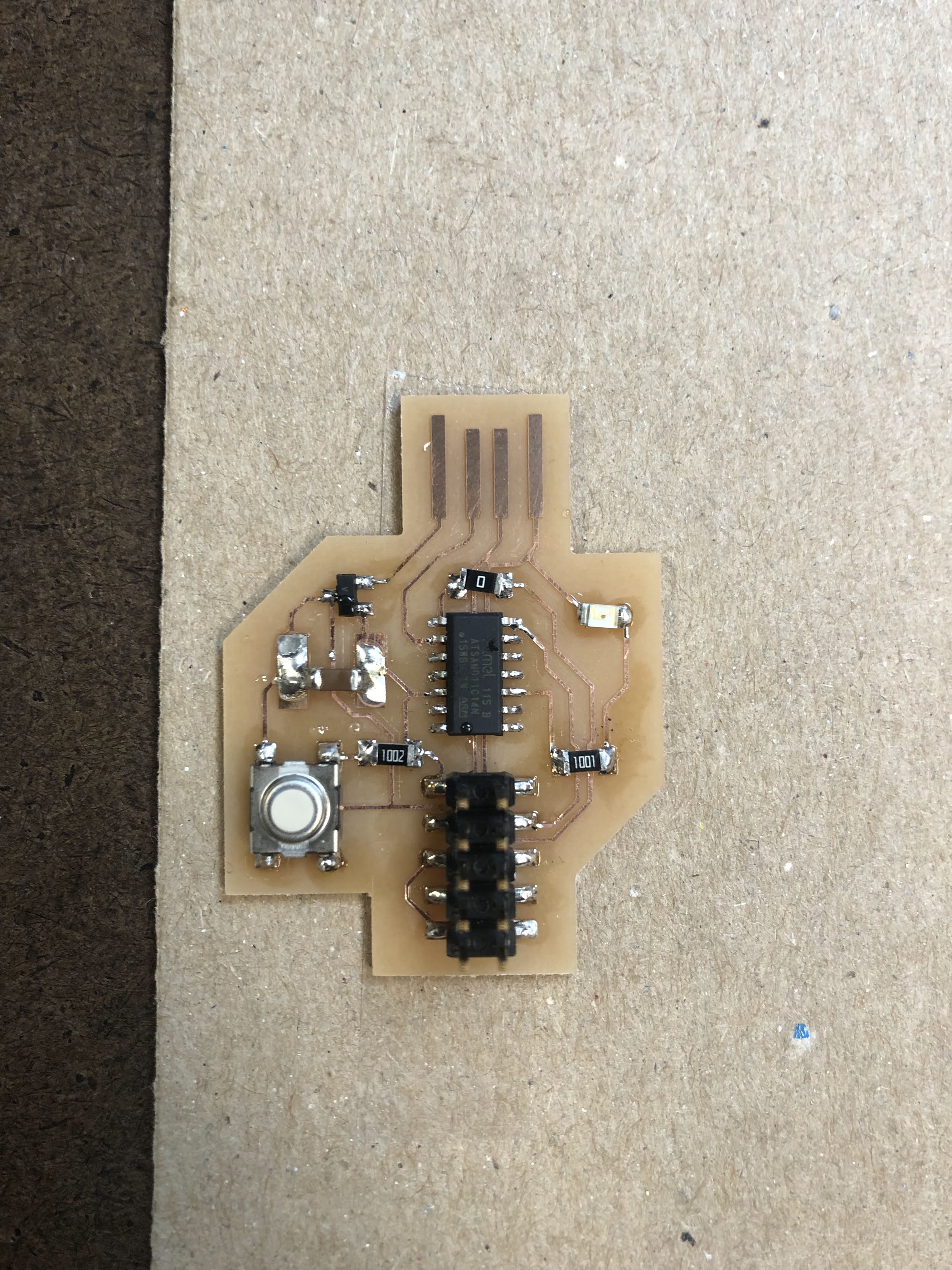
board after I soldered the parts; note the large amount of solder needed to bridge the gaps between the capacitor and the capacitor pads.

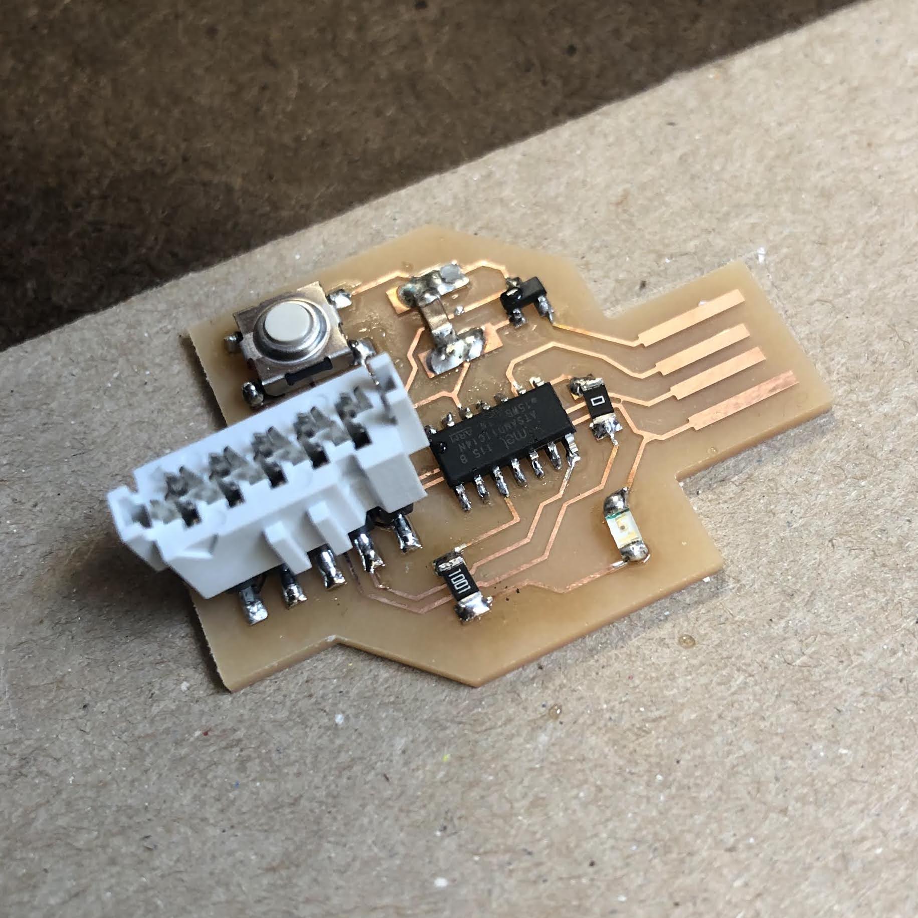
board with one 10-pin top; will have to get another one of these and connect them together to use my converter board.