How To Make (Almost) Anything Neil Gershenfeld
MCKENZIE ROSS HUMANN
MIT Department of Urban Studies and Planning
Input Devices
11.09.22
individual assignment:
measure something: add a sensor to a microcontroller board
that you have designed and read it
group assignment:
probe an input device's analog levels and digital signals
Create a Sensor
This week I wanted to create something that I could use for my final project - the vermi-composting bin that is designed to make it easy to maintain the best conditions for the worms and harvest castings.
Following this example from a previous fabacademy student who also made a vermi-compost bin, I decided to make a soil moisture sensor. A capacitative, or step-response, sensor can be used as a moisture sensor.
The step-response sensor has a transmitter and receiver wires connected to two conductive materials, e.g. copper The idea is to set the transmitter to a high voltage, read the voltage of the receiver sensor, then set the transmitter to a low voltage and read the receiver sensor again.
The difference between the two readings indicates the capacitance, which is simply a measure of an object's ability to store electric charge. Human touch or a change in the material between the sensor prongs will cause a change in the capacitance and this change is what is used to 'sense'.
See this post for a more detailed explanation of a capacitative sensor.
In my case, I am hoping the capacitative sensor will detect when soil is too moist or not moist enough in the composting bin. This means the sensor has to be sufficiently sensitive, and I'll have to calibrate it to make the raw readings meaningful in the context of soil moisture.
I used the diy moisture sensor example linked above and this step-response example to understand how to design the board.
Starting from my board design with the LED and button, I removed the LED and button and instead add a 6pin connector as well as 2 10M ohm resistors for the transmitter sensor.
I later read that adding a capacitor on the receiving sensor would also help in smoothing the voltage readings. After finishing the board design, I routed using similar routing as the LED and button board since this worked for me in the previous week.
I milled two boards, as the first board I milled did not separate two copper traces that were supposed to be separate. Unfortunately, in the second board I milled the end mill was dull so it was not the cleanest cut.
Then I stuffed the second board, but when I went to program it the programmer did not detect the board. After some testing with the multimeter to check my connections and test for shorts, I decided to stuff the first board.
I had to cut the copper traces that were not supposed to be connected and add a wire to reconnect the cut trace. This was particularly important because the two traces were the 5V trace going into the regulator and the 3.3V trace coming out of the regulator and going to the microcontroller.
So it was important for me to separate these otherwise my microcontroller would get too much voltage and be fried. This worked well enough, however the programmer still did not recognize the board. This was particularly frustrating because I was checking connections/shorts all throughout the soldering process to be extra careful.
Finally, I tried using a different programmer in the Arch lab and both boards were successfully bootloaded.
For the sensor, I created a connector using a 6pin head and wires and soldered the corresponding TX and RX wires to a copper plate that had already been used for a large square PCB.
I created two separate prongs from this board and separated the copper film. There is a possibility that the prongs are too far apart and I will need to make my own board instead of using this recycled copper plate.
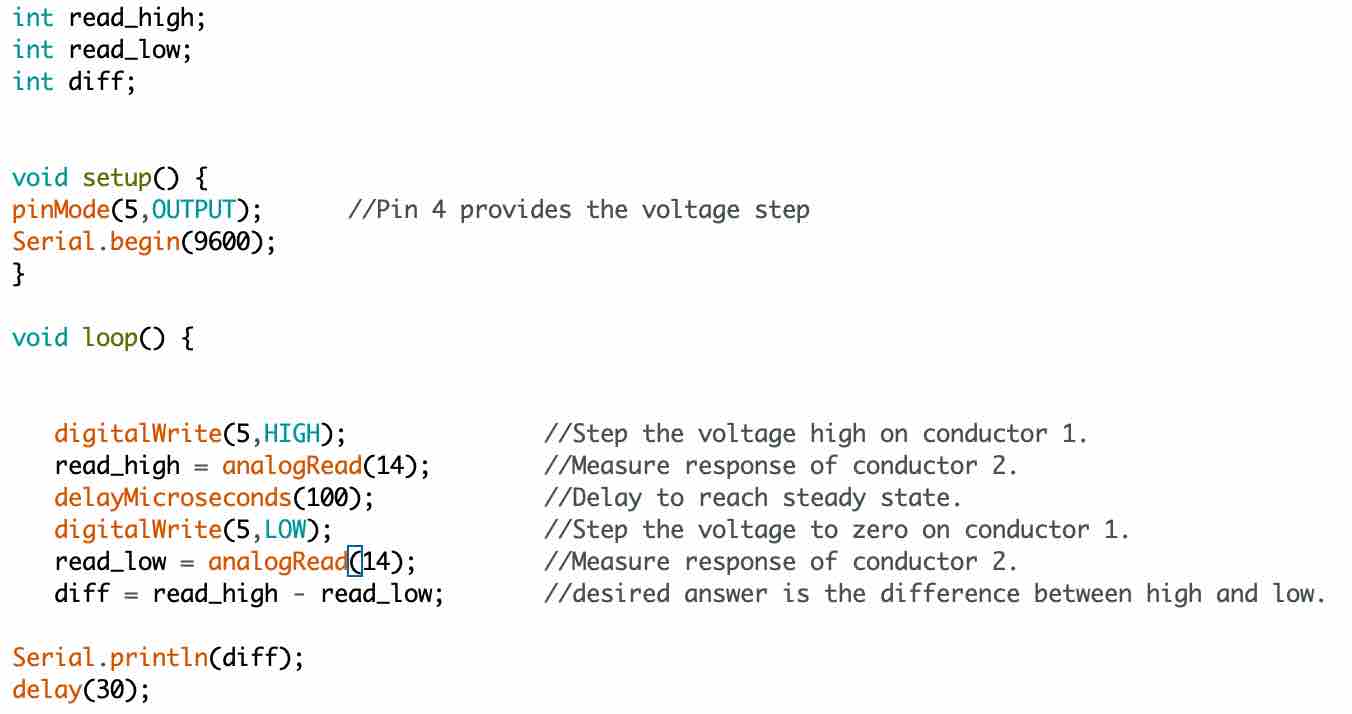
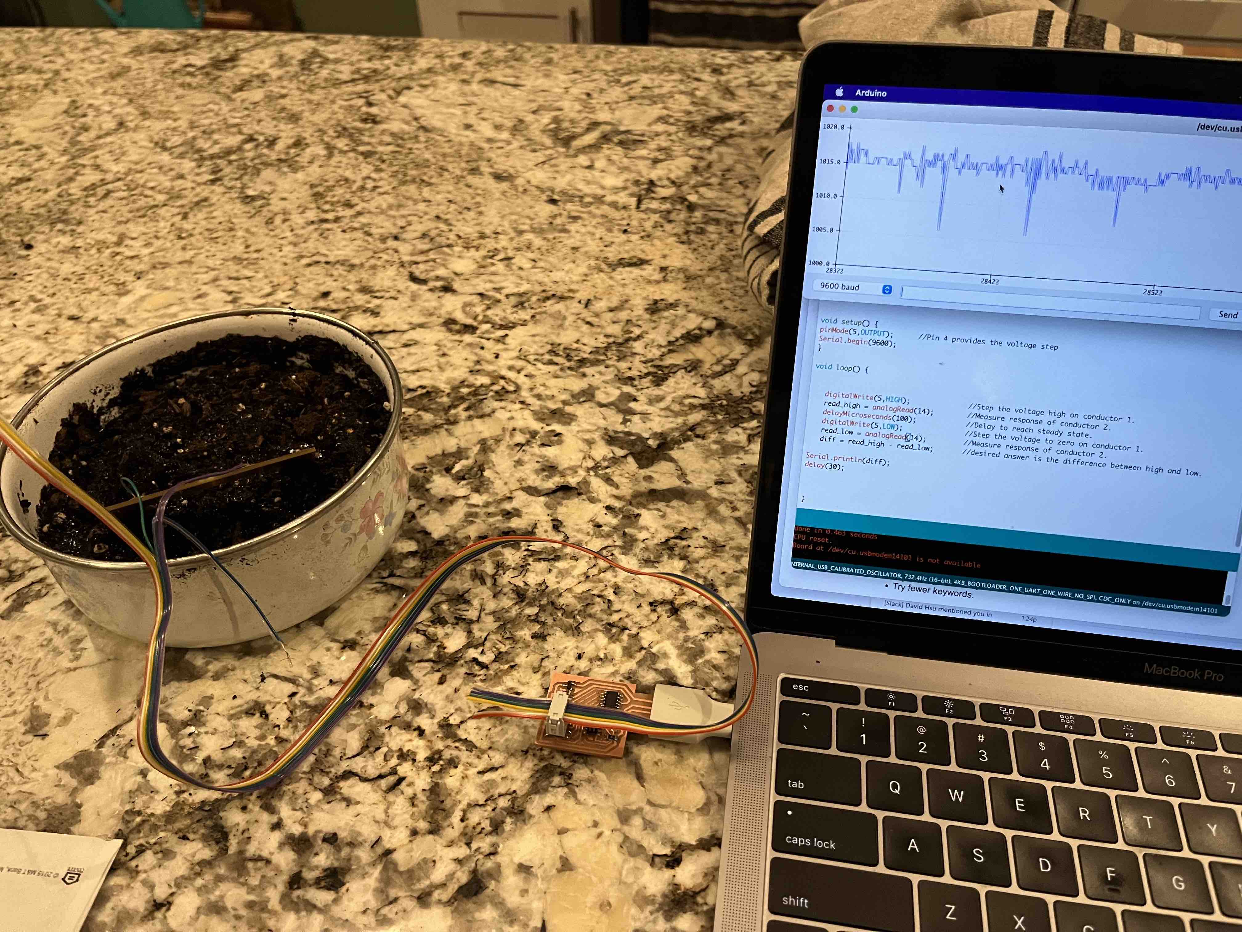
I modified the code from the step-response tutorial linked above to reflect the correct transmitter and receiver pins that I was using. At first I used code that did not average the voltage difference and so the readings were not very steady.
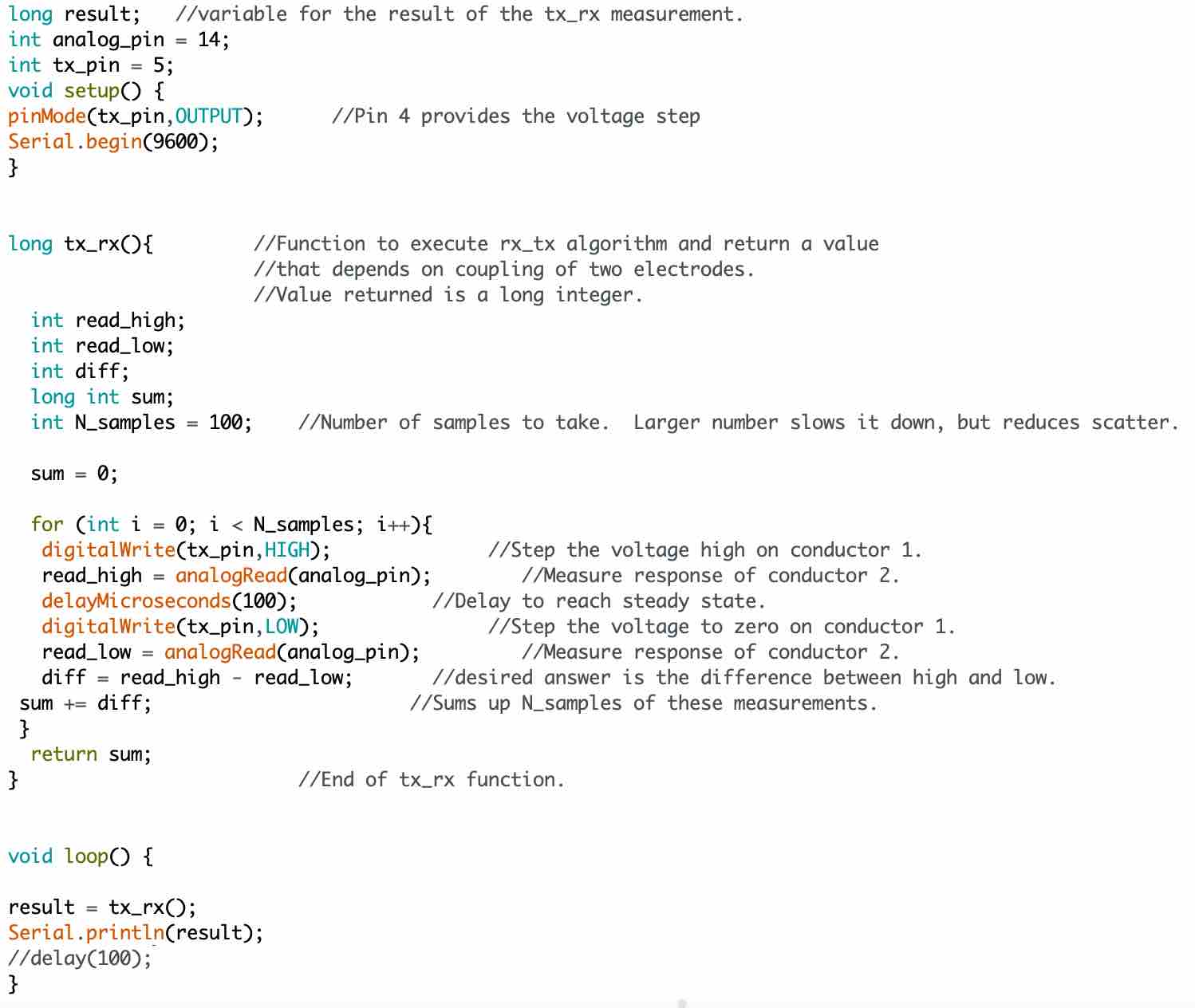
However, the sensor was indicating a change when I would touch the sensor board. Later I uploaded code that averaged the readings which created a much clearer indication when I touched the board.
I could even detect when my hand was close, but not touching the board.
With this success, I tried to test if the sensor could detect different levels of moisture in soil. I gathered one bowl of dry soil, one bowl of soil that was considerably wet, and one bowl of damp castings.
Initially I thought the sensor was working well as I got very different readings when I put the sensor in each bowl. However, I noticed that the sensor did not show a big difference between the damp castings and the wet soil.
Then I gathered more plastic bowls of soil, each one with 1 cup of soil and increasing teaspoons of water. The sensor did not sense any difference between these soils.
Then I realized perhaps the sensor readings are impacted by the material of the bowl more so than the contents and since the first three bowls I had used were all different materials this was driving the initial readings.
I will have to seek some guidance on what I can do to better sense the moisture content of the soil, which could require the prongs of the sensor to be closer together.
Basic code - no output smoothing
Code that sums last 100 readings to smooth output
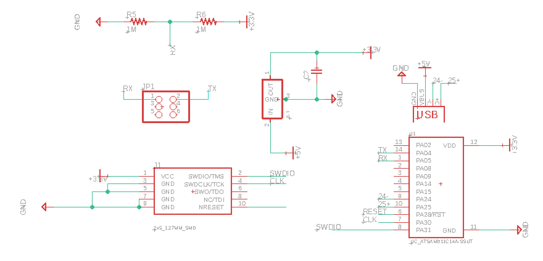
Schematic from Eagle
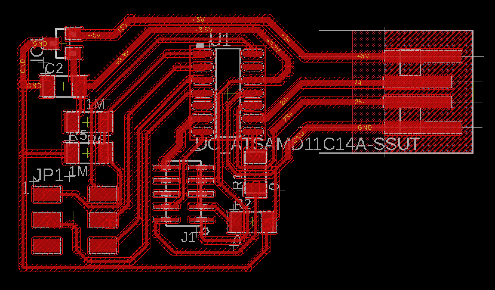
Board design
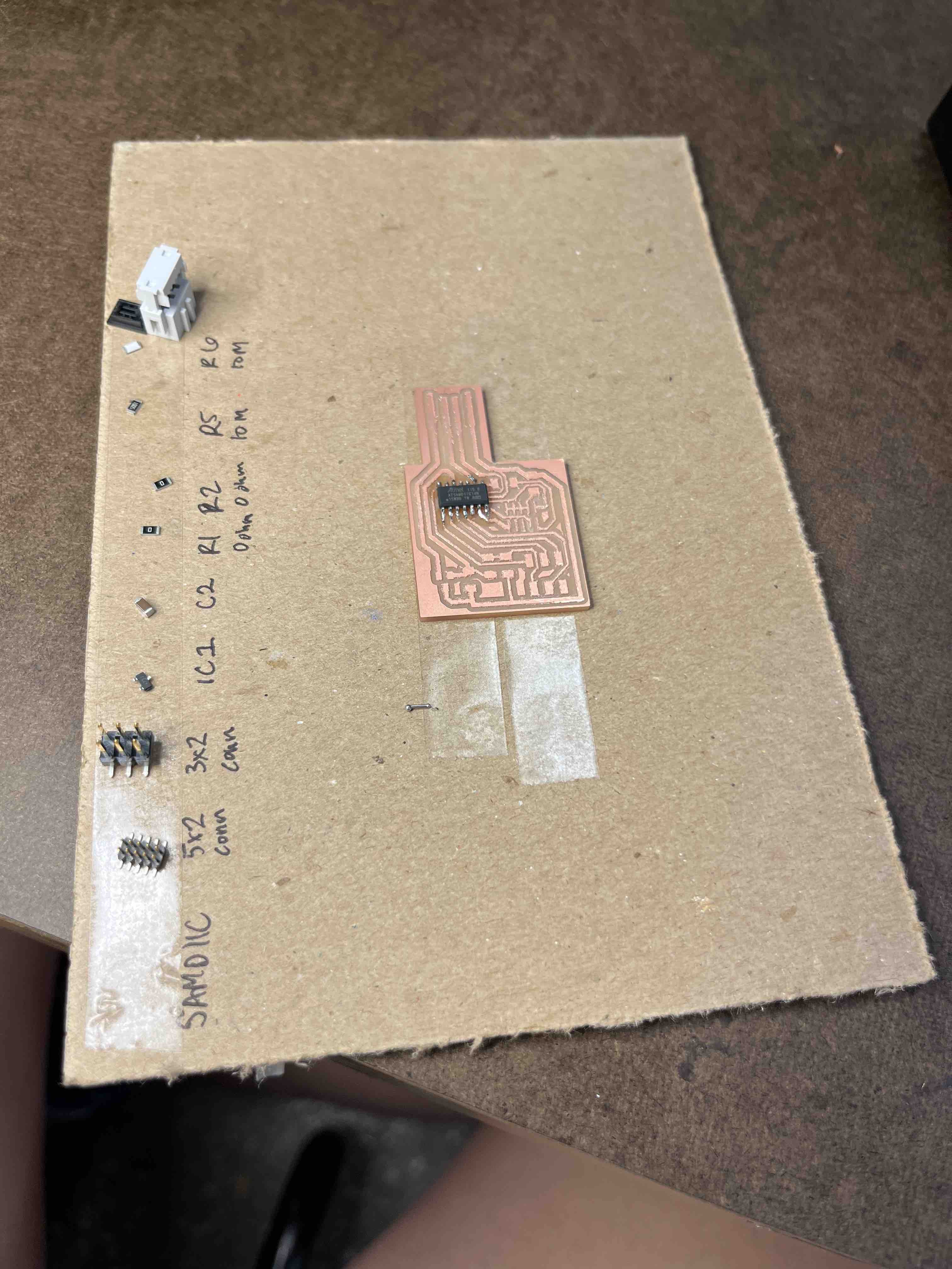
Preparing to solder
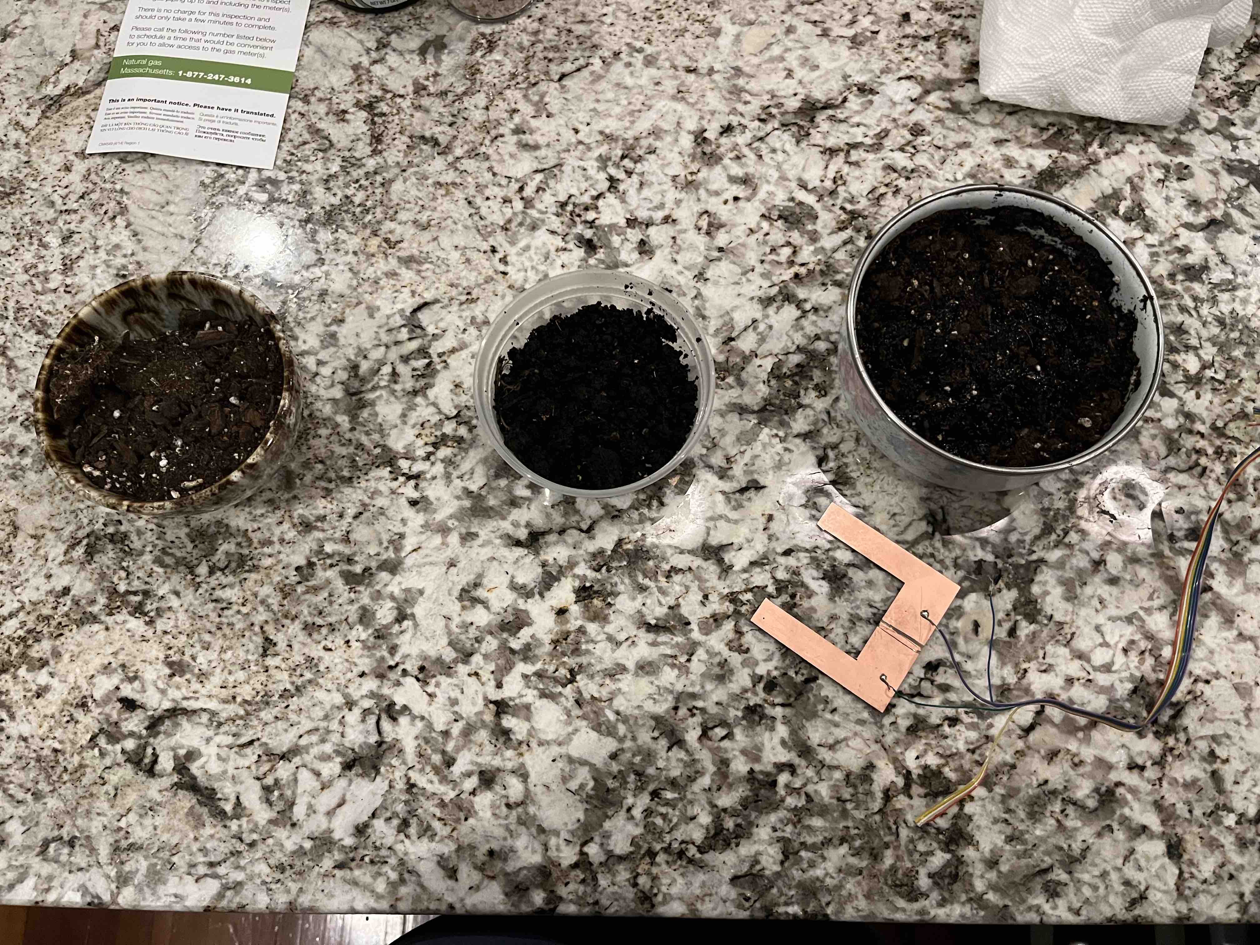
Three bowls of dry soil, wet soil, and damp castings next to the sensor.
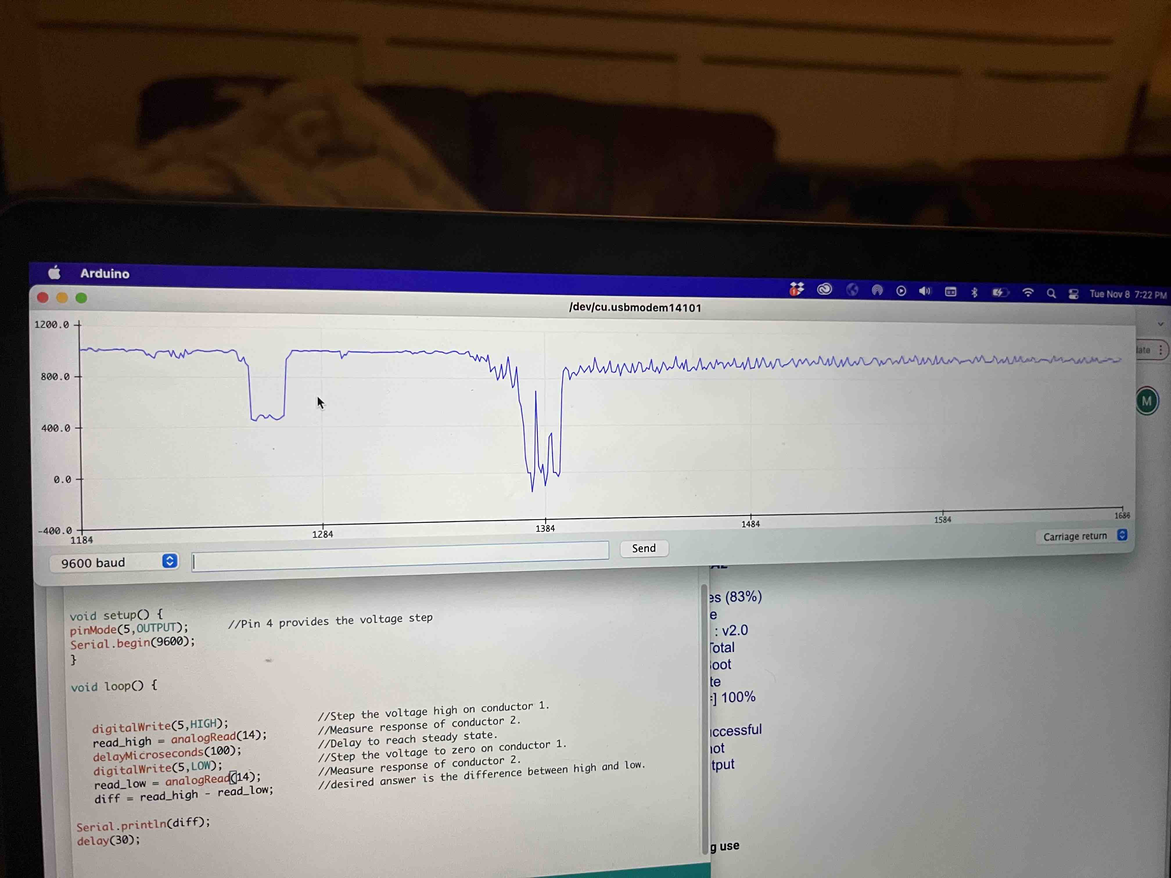
Plotter from code that did not do any averaging. The sharp drops are from tapping the sensor board.
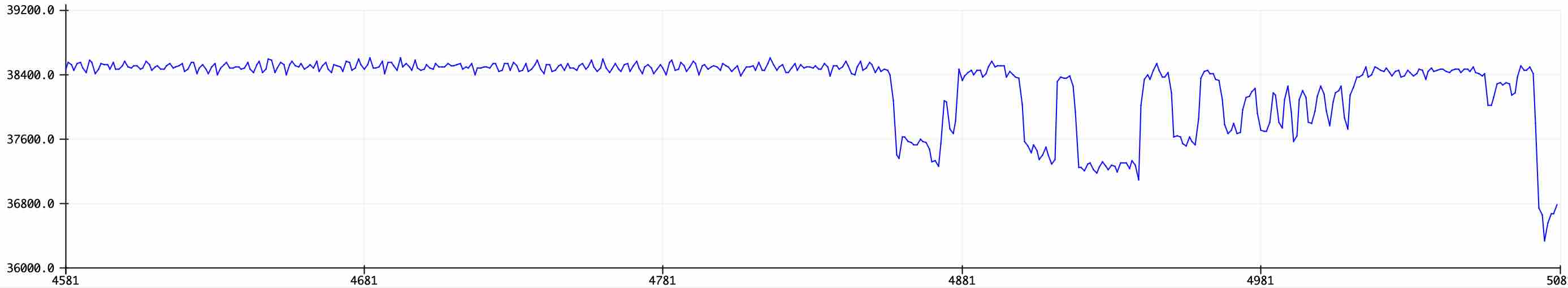
Plotter from code that adds up last 100 readings to smooth output.
Soil test set up
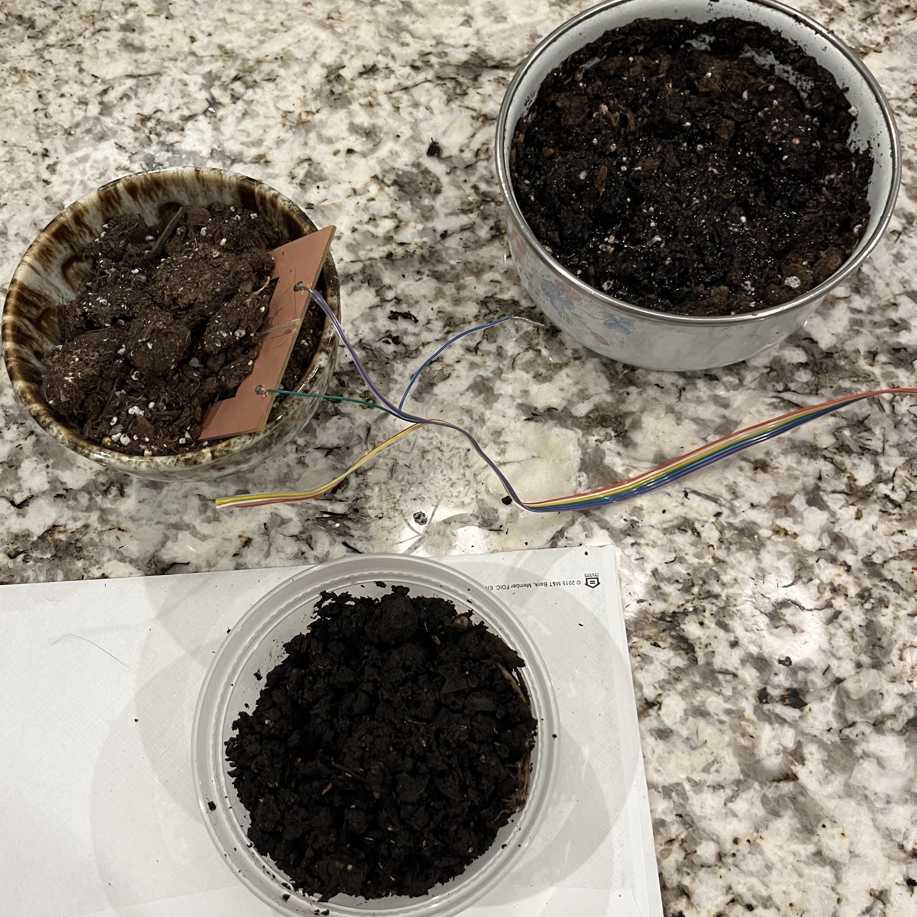
Soil test set up. Bowls are all different materials which impacted the capacitance readings.