08_INPUT DEVICES
This week I am going to test the Hall Effect sensor to see if I can potentially incorporate it in my final assignment.
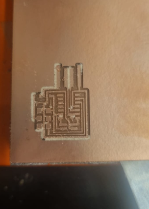
For some reason we couldn't identify for certain, this week the Roland machine is producing unusual results. The first milling attempt was a failure. The second attempt was a bit better. However, I couldn't immediately test it within the week as it took some time to acquire the thin four-pin headed cable. Also, once I received the cable and adjusted the orientation .
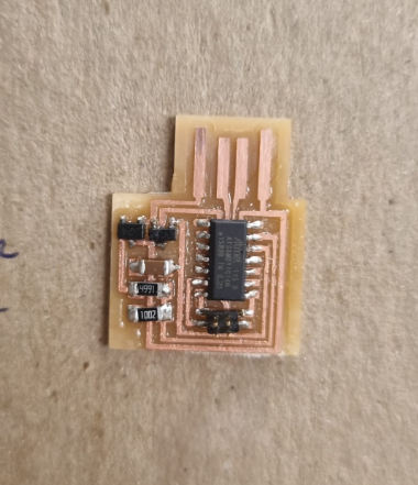
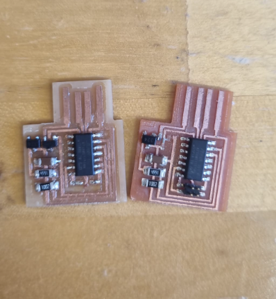
As I was trying to use the header, and shift its orientation, to interface correctly, the pressure took the traces off. So I had to make a new one.
Own Design:
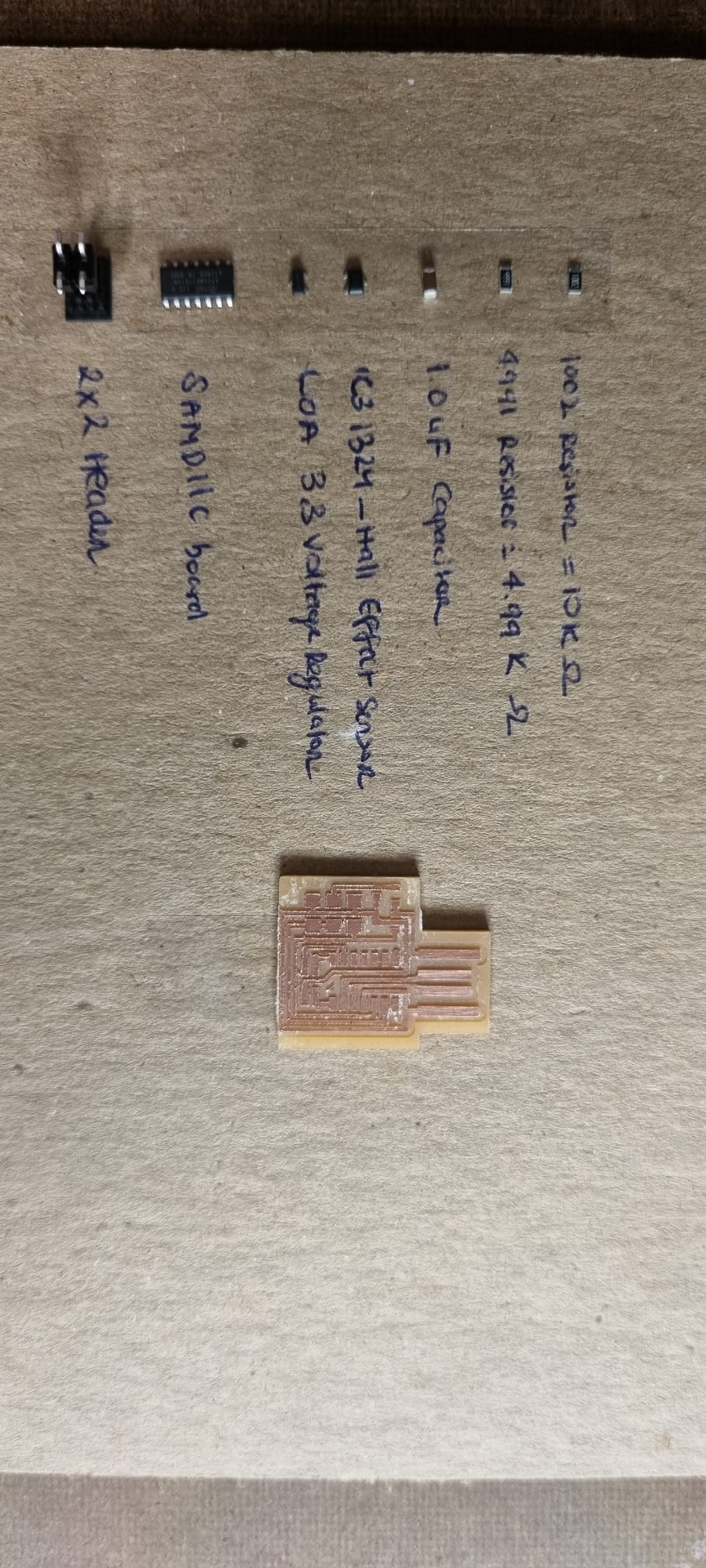
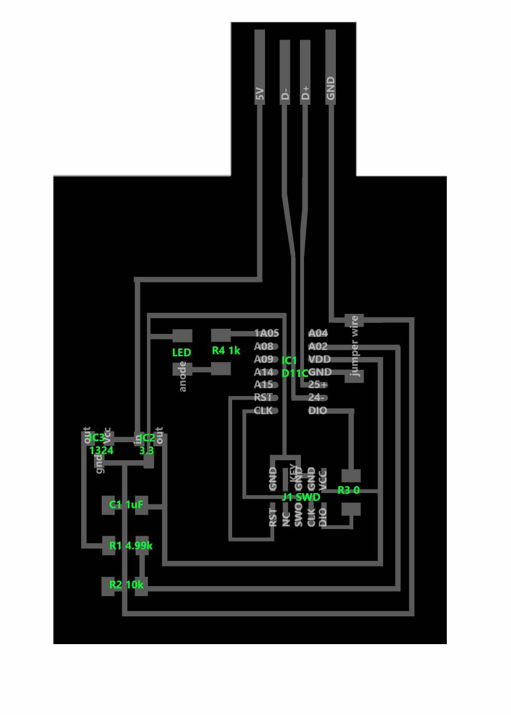
So this week's actual assignment is to add a sensor to a board we design.
For this assignment, I decided to combine the hall effect sensor with blinking lights.
Neil's code was altered so that the LED would blink faster in higher measurements:
#define nsamples 100
const int ledPin = 5; // Pin number for the LED (PA05)
int blinkDelay = 1000; // Initial delay between LED blinks in milliseconds
void setup() {
//
// start serial
//
SerialUSB.begin(0);
//
// set up ADC
// assumes Arduino core has set up ADC clock
//
ADC->REFCTRL.reg = ADC_REFCTRL_REFSEL_INTVCC1;
// reference 1/2 VDDANA
ADC->AVGCTRL.reg = ADC_AVGCTRL_SAMPLENUM_1;
// average 1 sample
ADC->CTRLB.reg = ADC_CTRLB_PRESCALER_DIV128 |
ADC_CTRLB_RESSEL_10BIT;
// prescaler divide by 128, 10 bit result
ADC->INPUTCTRL.reg = ADC_INPUTCTRL_GAIN_DIV2 |
ADC_INPUTCTRL_MUXNEG_GND | ADC_INPUTCTRL_MUXPOS_PIN0;
// gain 1/2, ground negative, AIN[0] (pin 13) positive
PORT->Group[0].DIRCLR.reg = PORT_PA02;
// input on PA02 (pin 13)
PORT->Group[0].PINCFG[2].reg |= PORT_PINCFG_PMUXEN;
// enable multiplexer for PA02
PORT->Group[0].PMUX[1].reg = PORT_PMUX_PMUXE_B;
// function B (analog input) on PA02
while (ADC->STATUS.bit.SYNCBUSY) {};
// wait for sync
ADC->CTRLA.bit.ENABLE = true;
// enable
// Set LED pin as output
PORT->Group[0].DIRSET.reg = PORT_PA05; // Set PA05 as output
}
void loop() {
uint32_t result = 0;
//
// accumulate readings
//
for (int count = 0; count < nsamples; ++count) {
while (ADC->STATUS.bit.SYNCBUSY) {}; // wait for sync
ADC->SWTRIG.bit.START = true; // start conversion
while (ADC->INTFLAG.bit.RESRDY == 0) {}; // wait for ready
ADC->INTFLAG.reg = ADC_INTFLAG_RESRDY; // clear flag
result += ADC->RESULT.reg; // accumulate result
}
//
// send framing
//
SerialUSB.write(1);
SerialUSB.write(2);
SerialUSB.write(3);
SerialUSB.write(4);
//
// send reading
//
SerialUSB.write(result & 255);
SerialUSB.write((result >> 8) & 255);
SerialUSB.write((result >> 16) & 255);
// Adjust the blink delay based on the sensor reading
blinkDelay = map(result, 0, 1023, 2000, 100);
// Blink the LED
PORT->Group[0].OUTTGL.reg = PORT_PA05; // Toggle the LED pin
delay(blinkDelay); // Delay for the blink interval
}