# Week 1
**Computer-Aided Cutting**
> Characterize your laser cutter's focus, power, speed, rate, kerf, joint clearance and types.
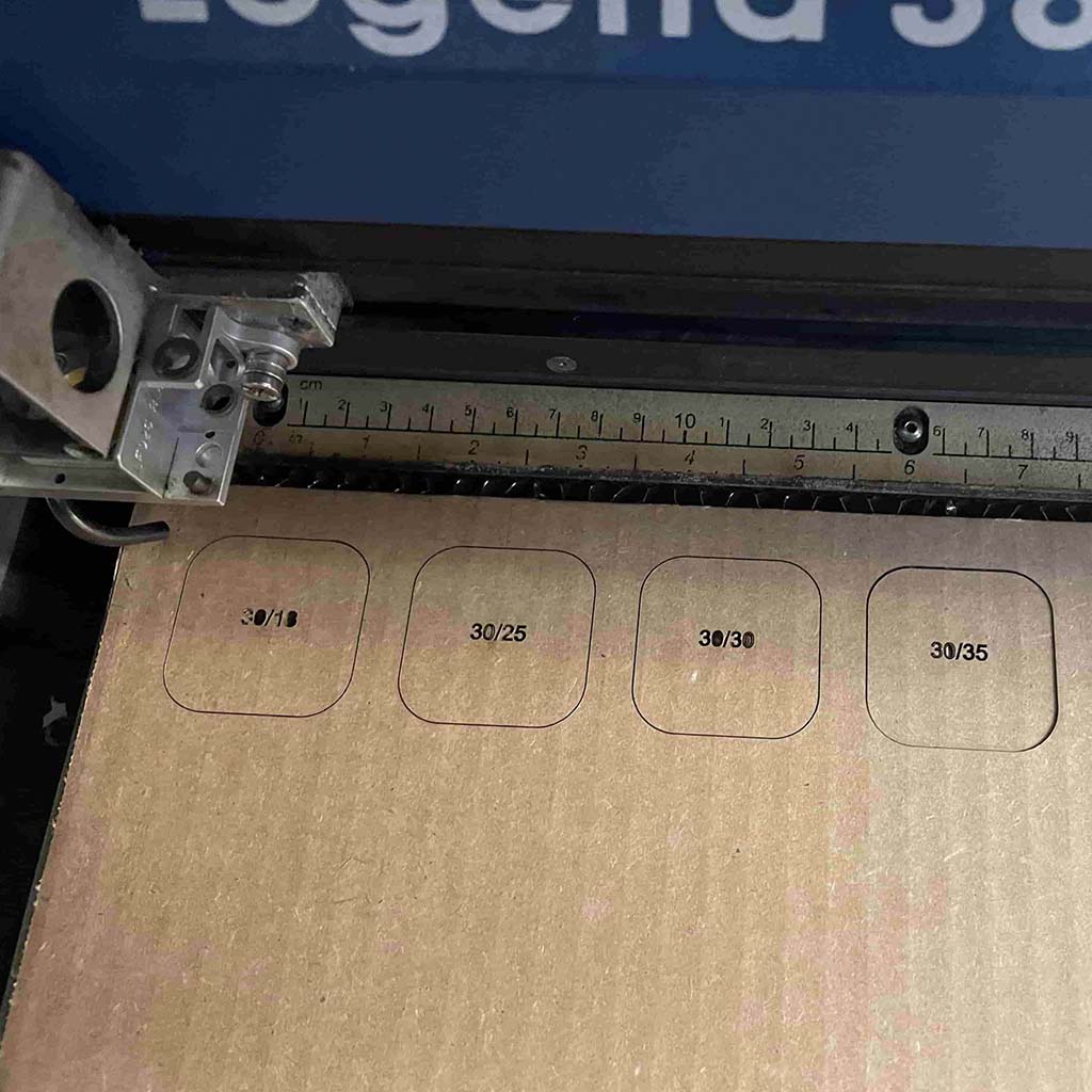
For characterizing the laser cutter, we drew several rounded corner rectangles on different layers in the Rhino.
And the target material is the cardboard as suggested. We tried several settings by varying power and speed.
According to our test, power=30; speed=35; frequency=500 gives us the best result.
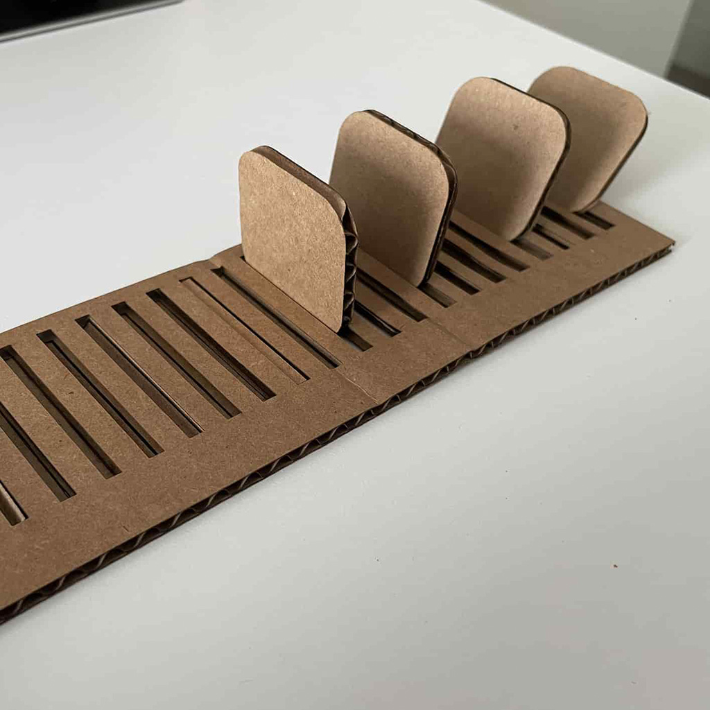
Since many of us is thinking of assembling multiple parts, another test we did is to cut a rectangle with many pockets -
With the gap between 3mm to 5mm, and the intervals of 0.1mm. Finally, we noticed that 4mm works the best.
# Week 2
**PCB Fabrication**
> Characterize the design rules for your in-house PCB production process.
> *Extra credit: Send a PCB out to a board house.*
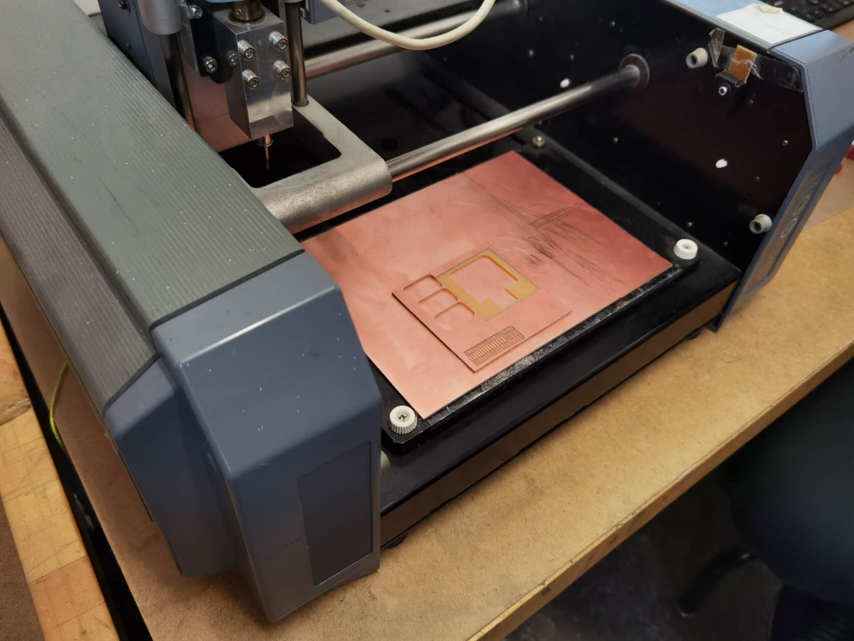
There are two machines in the shop - MDX-20 and SRM-20. For group test, we fabricated our board using the MDX-20.
We went through all steps of using the machine and learned the safety cautions. First, always have a good habit of putting tools in order.
Second, do not move the board between milling the traces and boundary.
Third, remember to keep the work table clean.
The entire group keep the rule in mind and build the board:
# Week 3
**3D Scanning and Printing**
> Test the design rules for your 3D printer(s).
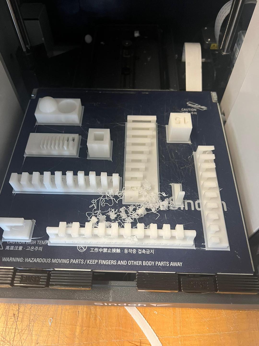
There are two types of 3D printers in the shop, i.e., Sindoh 3DWOX1 (white) and DP200 (black)
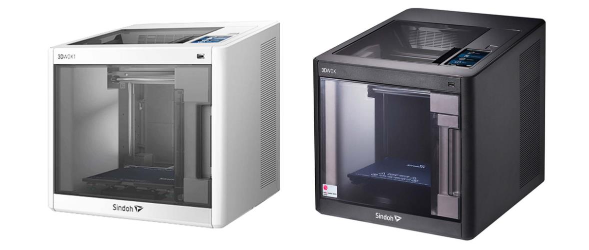
Before printing our own design, we run a few tests to understand the design rules for our printer.
It is essential to figure out the angle that could be printed without requiring a support. Also, it is possible to vary some settings (wall thickness, infill, etc.) that affect not only structural aspects but also printing time.
For instance, the maximum angle that resulted in a piece without issues was 50.
# Week 4
**PCB Design**
> Use the test equipment in your lab to observe the operation of a microcontroller circuit board.
# Week 5
**CNC Machining**
> *Do your lab's safety training.*
> Test runout, alignment, fixturing, speeds, feeds, materials, and toolpaths for your machine.
To conduct the work, we went to N51 and learned from Chris.
He showed us the entire procedure from carrying the material to the working bench,
fixing the material on the bench, to checking the designed CAD drawing, exporting G-code.
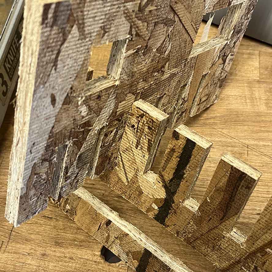
We fabricated the test board and found that the pocket should be .42 inches to get the best result.
# Week 6
**Embedded Programming**
> Compare the performance and development workflows for other architectures.
For this week we compare the development environment for two hardware:
* Arduino
* STC89C51
For Arduino, we can plugin the hardware with a USB connection. Then, it is easy for us to code in Arduino IDE and upload the code easily. And it is worth noting that this IDE also has many useful tool like serial monitor which is convenient to do debug.
For STC89C51, a member of us used that many years ago. The hardware connection is the same to Arduino, however, for software side, we need to code using Keil first. Then, we need to compile the code and then use the specific software to download the code to microcontroller.
According to our comparison, the Arduino is much better than STC.
# Week 7
**Molding and Casting**
> Review the safety data sheets for each of your molding and casting materials, then make and compare test casts with
each of them.
> *extra credit: Try other molding and casting processes.*
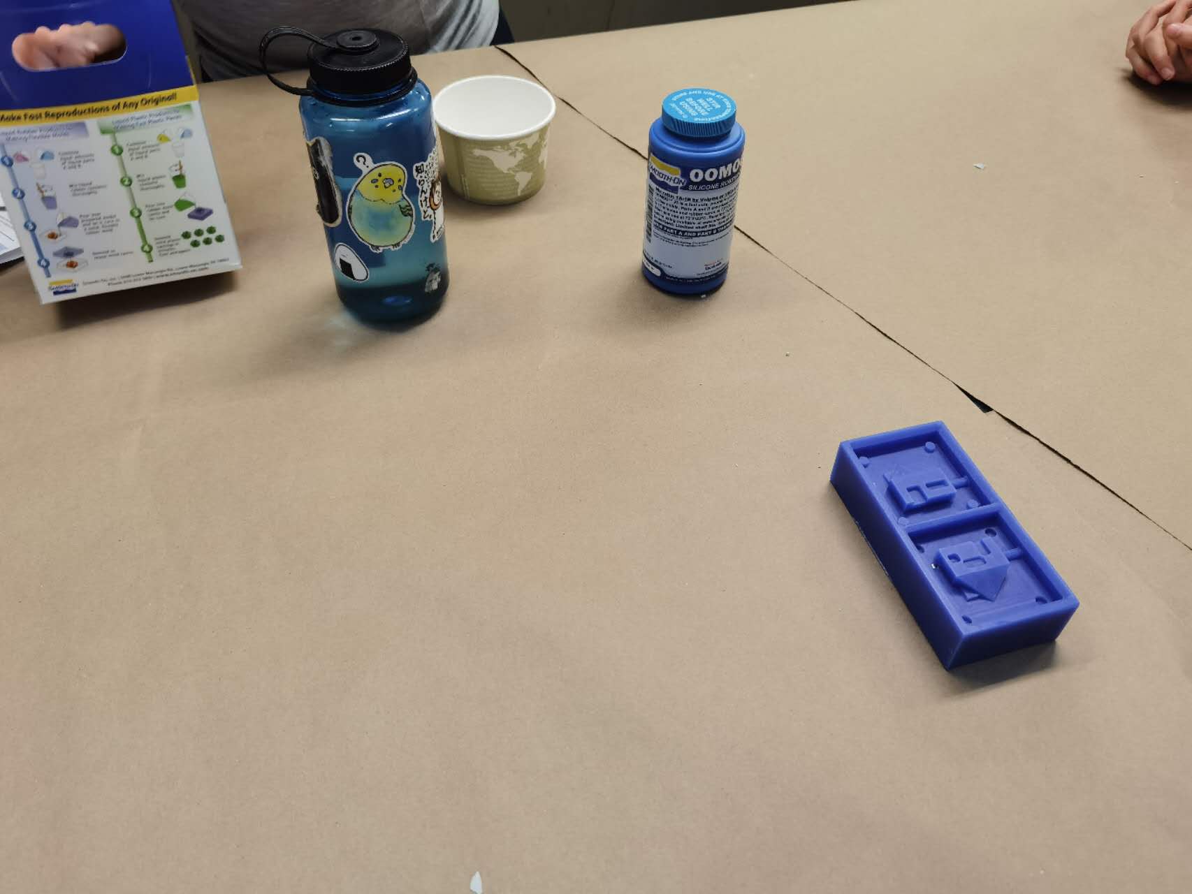
We scheduled tutorial meeting with Jen so that she could show us everything about molding and casting.
One very important note we learned is that we should always have the hole for the air (for two-sided). Otherwise the material cannot fill the entire space.
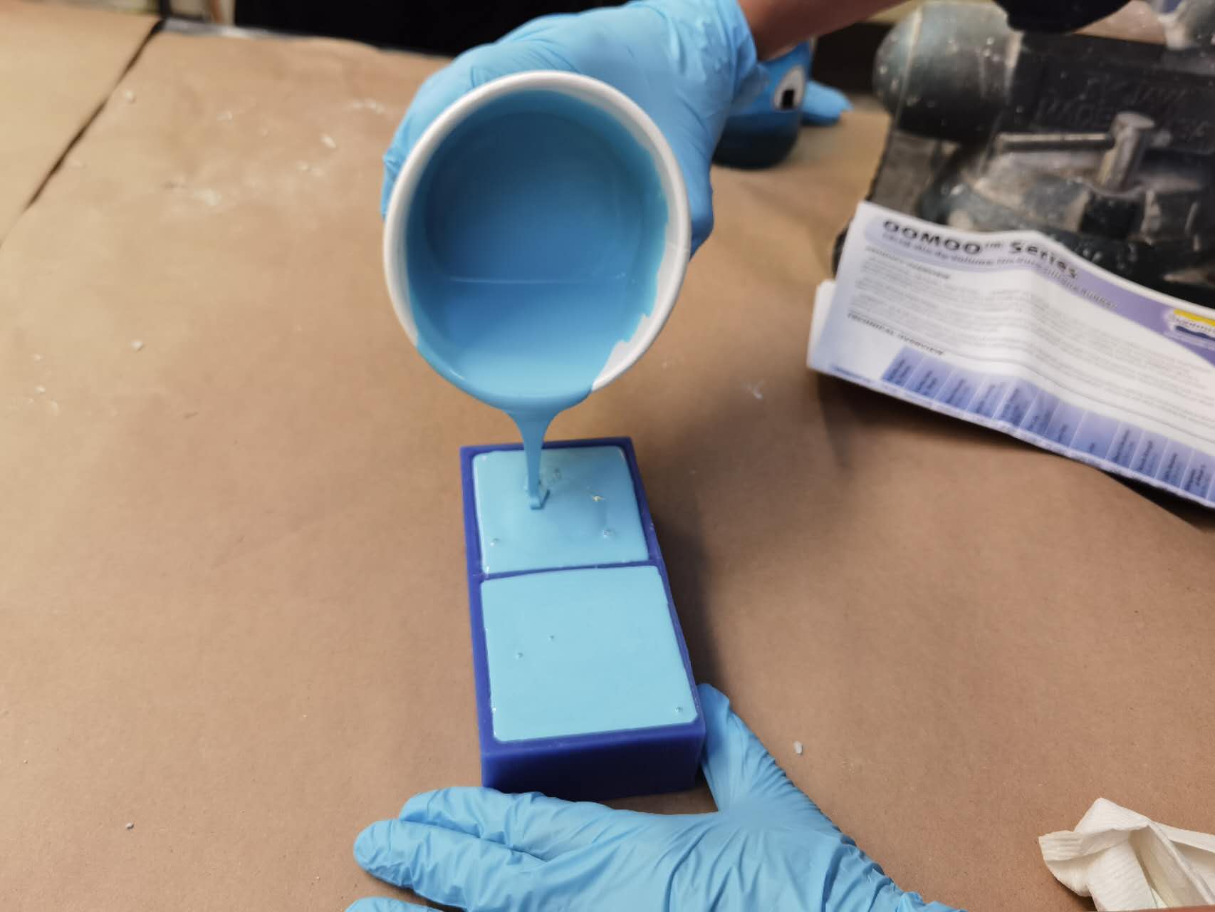
We read the safety instruction for two types of materials (which are non-toxic), and then tried each of them.
When filling the material into the mold, we need to be very careful to reduce air bubbles.
# Week 8
**Input Devices**
> Probe an input device's analog levels and digital signals.
# Week 9
**Output Devices**
> Measure the power consumption of an output device.
# Week 10
**Networking and Communications**
> Send a message between two projects.
# Week 11
**Interface and Application Programming**
> Compare as many tool options as possible.
For this group assignment, we compared the following tool options:
* PyQt5: The package is quite huge, and very powerful. To use it, I need to take care of every detail to construct the interface and the logic behind it. But the good thing is that we can get full support from the Python community.
# Week 12
**Mechanical Design + Machine Design**
> design a machine that includes mechanism+actuation+automation+application
> build the mechanical parts and operate it manually
> document the group project and your individual contribution
This has been the most challenging week we had and the first project that should be entirely done in group. In less than 7 days, we had to design, build and operate a machine. Although it was only project per section and there were some shortcuts we could use(e.g., modular things, 3D printing design, etc.), it was not straightforward to create a machine that was automated and controlled by a friendly interface.
<h3>Ideating</h3>
<p>1. The first step was to discuss potential projects to be built. We met the day after the recitation and each of us brought some ideas:</p>
* Pancake printing machine
* Circle drawing machine
* Interactive housing
* Folding clothes machine
* Bubble making machine
<p>2. After some discussion and feedbacks, we voted to define which project to focus on.
We ended up merging two of the projects, and decided to build a Circle Drawing Pancake Machine - aka Sketchy (Pan)Cake Machine.</p>
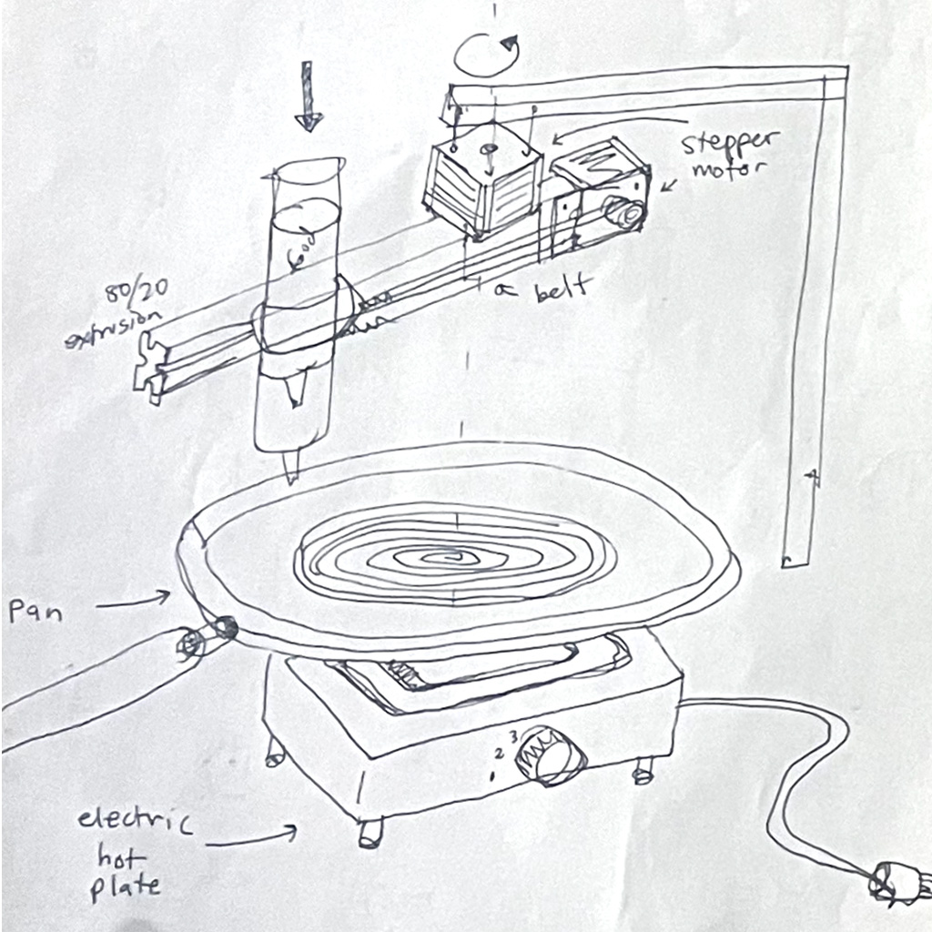
After defining the project, the team did some sketches, and we used the following as a starting point.
Essentially, the machine should have a metal structure with a radial system for drawing and a small grill with a pan on the base part.
<video width="320" height="240" controls>
<source src="assets/Week12/2.mp4" type="video/mp4">
</video>
<hr>
<h3>Work Division</h3>
<p>Then, we divided the project in smaller parts and allocated to different teams according to skills:</p>
<ul>
<li>Form Construction: built a structure made of metal triple rails and metal sheets.</li>
<li>3D Printed Parts: design and print plastic parts for connecting parts, finishing and supporting motors.</li>
<li>Extruder Mechanism: design and build motorized part to extrude pancake batter.</li>
<li>Linear and Radial Arms: design and build arms to move the extruder, changing the radius and the position of the drawings.</li>
<li>Software: program the machine to control electronic motors and create a friendly interface.</li>
</ul>
<hr>
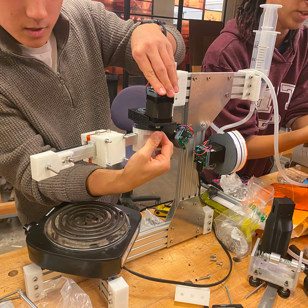
<h3>Building Parts</h3>
In parallel, all teams started to work on each of the project tasks:
<h4>Form Construction</h4>
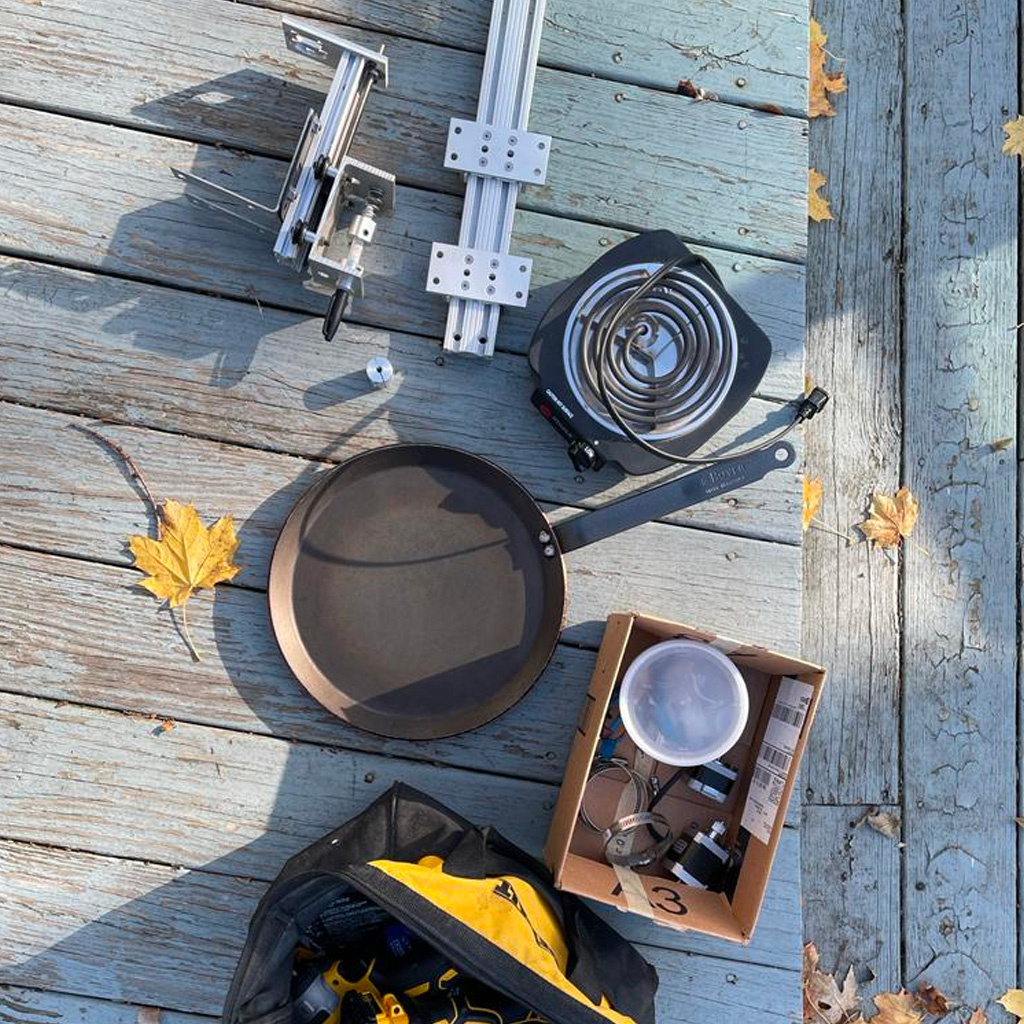
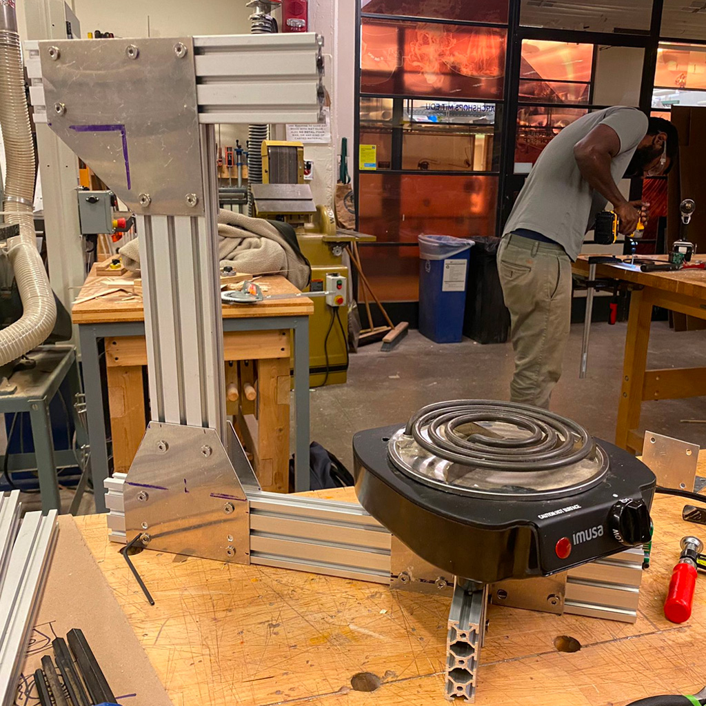
1 Following the design, we selected some parts that were necessary for the machine, In addition to the materials that were provided, we used a hot plate, pan and small structural metal parts.
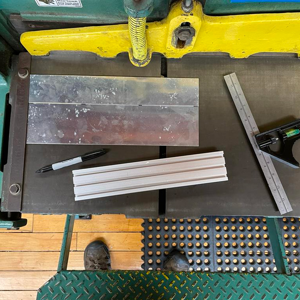
2 Then, Jerome cut all the parts according to the required sizes. We used the triple metal rails and connected them with aluminum plates.
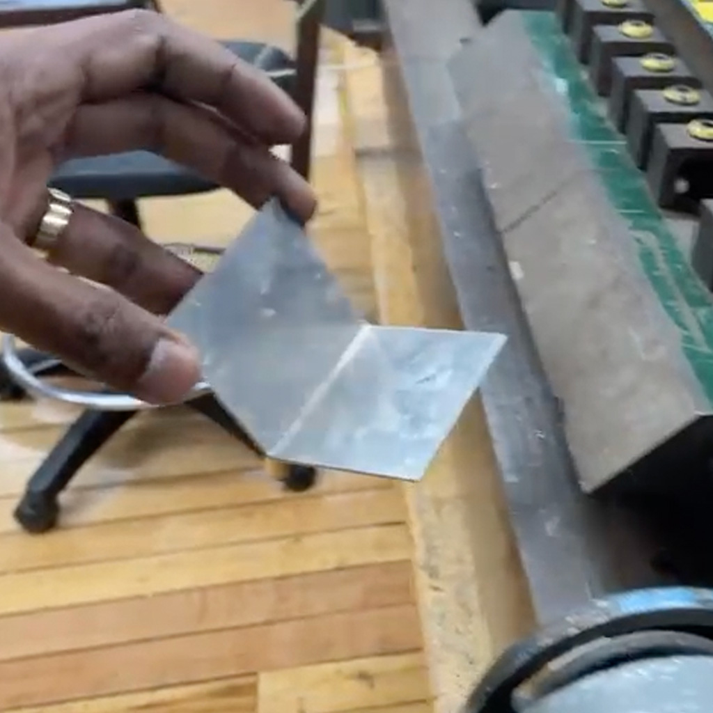
3 At the shop, we were able to connect the pieces and build the basic structure to which all the motors and other components should be connected.
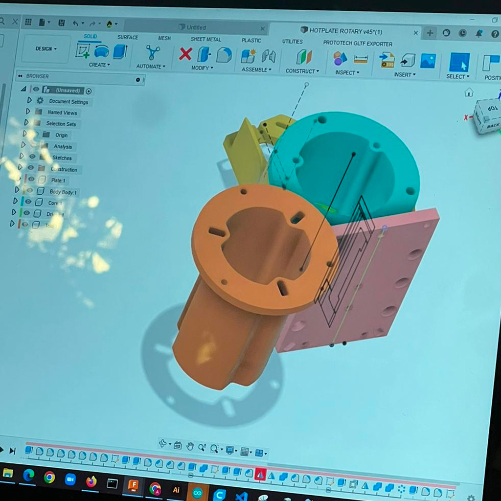
<h4>Printed Parts</h4>
1 With the structure partially done, we figured out some 3D printed parts we needed. We used the documentation available at Beehive documentation to adjust dimensions.
For example, we printed a few end caps to make the machine more stable and a few mounts to support the motors and rails.
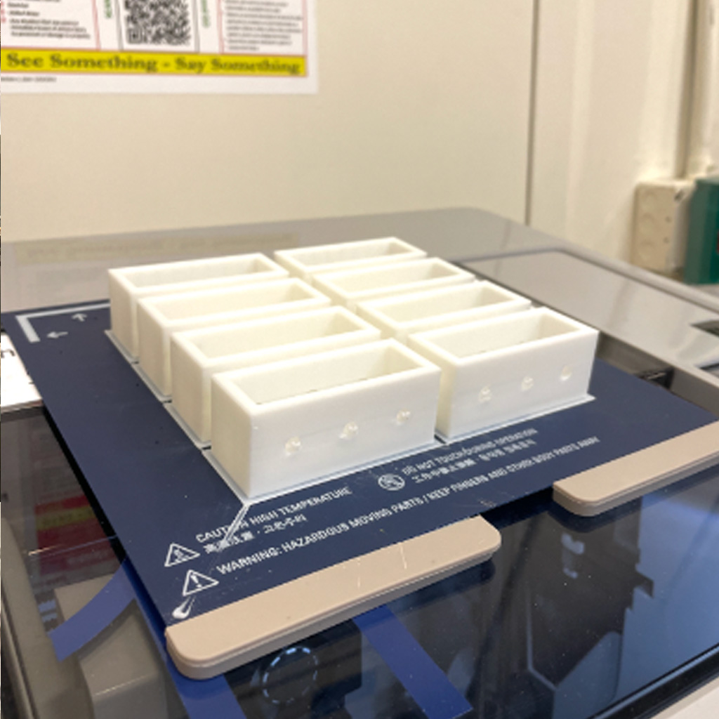
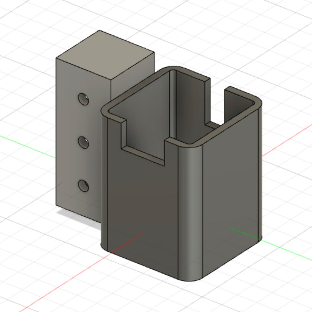
Some of them didn't work as expected and, in some cases, the pieces that we needed to fix them were not available. So, we had to reprint or adapt, cut and fix some of them.
<h4>Extruder Mechanism</h4>
1 This was one of the most challenging parts, especially because it depends on the viscosity of the pancake batter and the accuracy of the arm movements. The team decided to test some potential alternatives for the extruder mechanism.
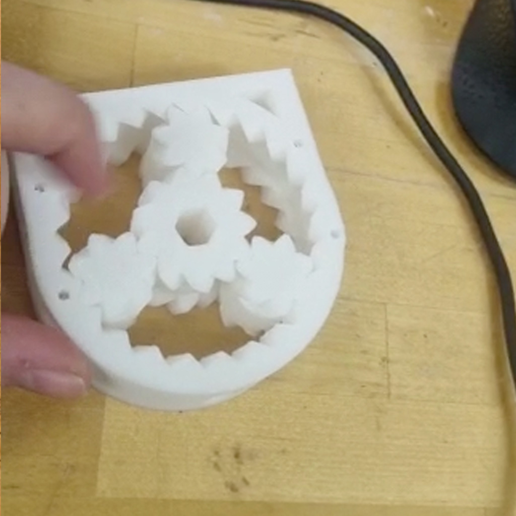
2 Using a plastic tube and a few laser cut parts, we built a peristaltic pump that control the flow of the batter using one of the motors.
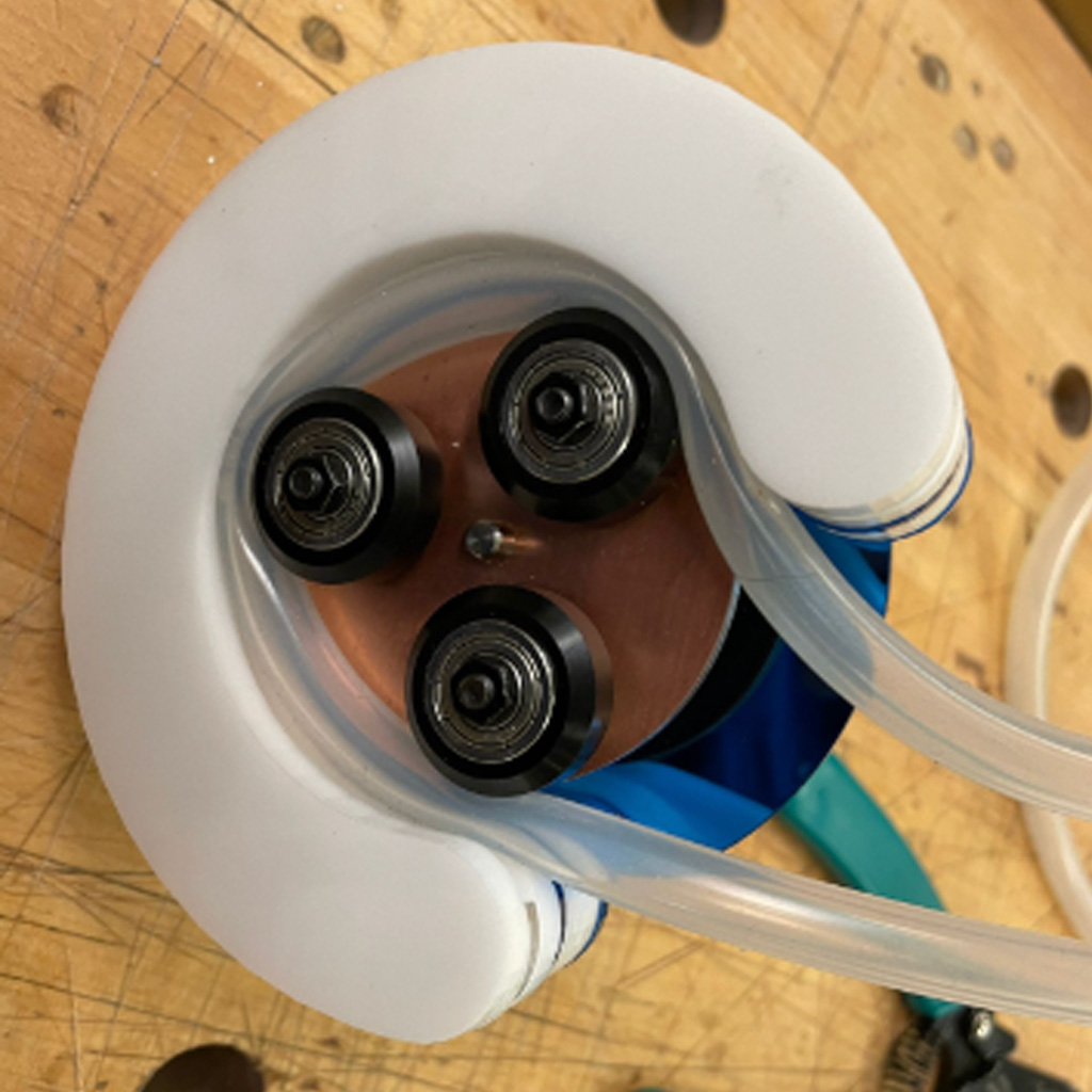
3 As a backup plan, the team also built another peristaltic bump but using the 3D printer.
4 After a few tests, we were relatively confident about the first option.
<video width="320" height="240" controls>
<source src="assets/Week12/12.mp4" type="video/mp4">
</video>
<h4>Linear and Radial Arms</h4>
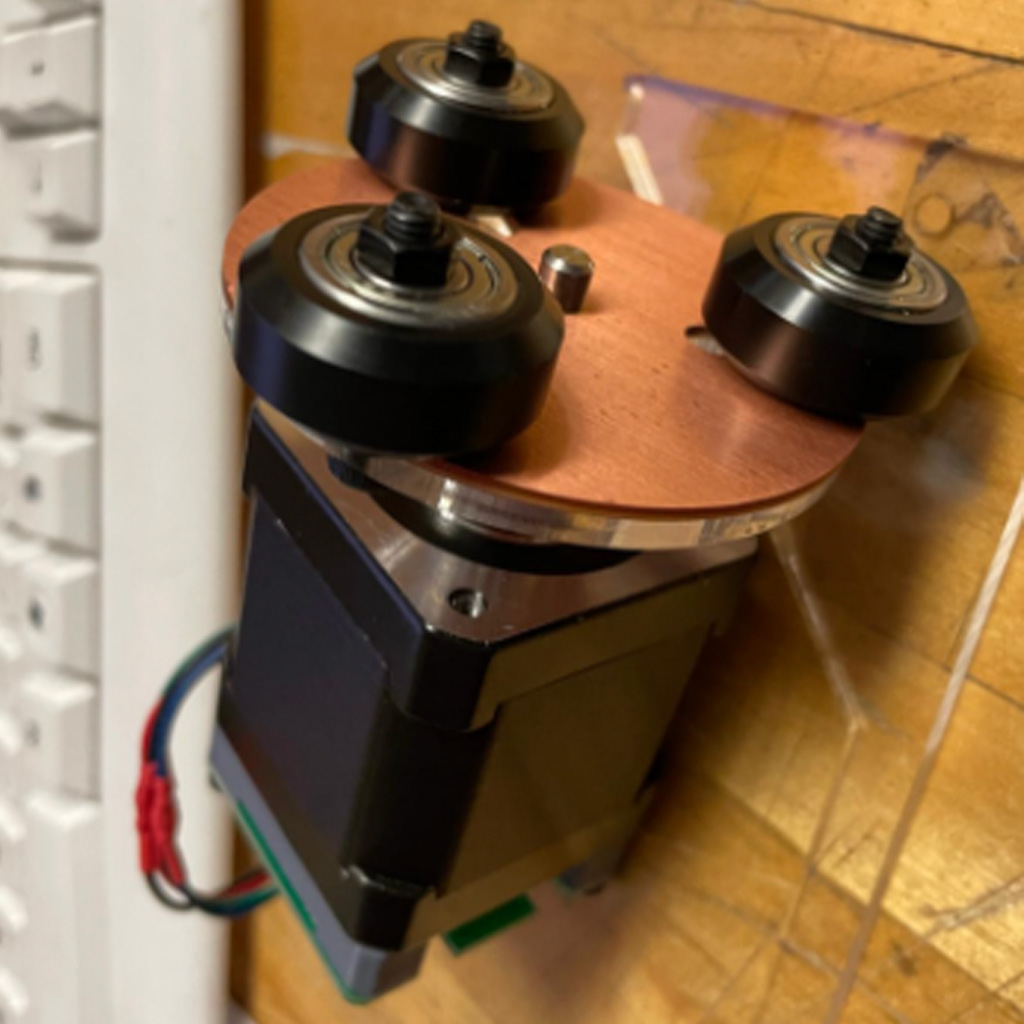
<p>1. To drive the movements, we needed to build two mechanisms - linear and radial - that would be individually controlled by motors.
The linear part was built using another smaller rail that we had and mounting the motor connected to a rubber band.</p>


<p>2. The radial movement was controlled by another motors that was mounted to the top structure.</p>
<p>3. In order to connect both motors, it was necessary to 3D print some additional parts.</p>
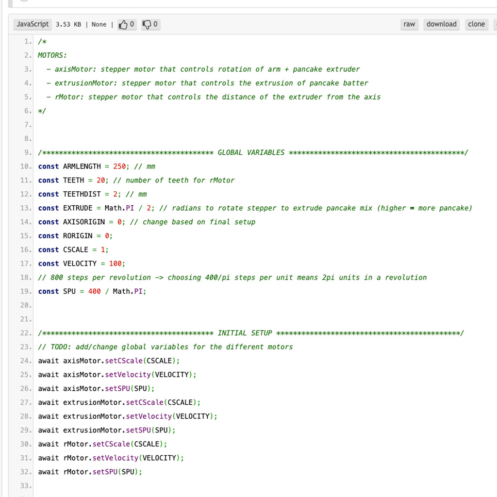
<h4>Software</h4>
<p>1. The software team started to work in parallel to learn how to use the modular things project.
In the first few days, they were able to create a code that could control the drawing movements based on the 2 motors we were using.</p>
<p>2. Also, they created a basic interface that could translate a hand drawing to the right coordinates used to drive the movements</p>
<p>3. Lately, they updated the visual and create a more friendly interface for the user's drawing.</p>
<h3>Combining the work</h3>
<p>1. With all parts almost done, we started combining all the individual parts.</p>
<p>2. We were finally able to see the whole machine assemble and could start testing how the different mechanisms worked together.</p>
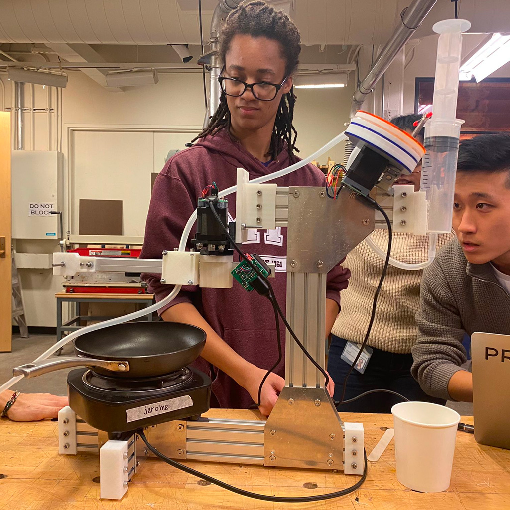
<p>3. We had a few issues on controlling the machine and extruding the pancake batter. But, after some adjustments, we finally got our first personalized pancake.</p>
# Week 13
**Wildcard**