Week 5: Electronics Design
This week's project was to redraw an echo hello-world board, add (at least) a button and LED (with current-limiting resistor), check the design rules, make it, and test that it can communicate
For designing my circuit, I opted to use Eagle, integrated within Fusion 360. The first step was importing the library of parts for our class into Eagle, so I could use them in designing my circuit.
Before connecting any components in the schematic, I first wanted to get a general idea of what components I would need, and the respective voltages/capacitances/resistances needed.
Thought process - 0hmm reistor and 100 ohm (voltage drop on led was 1.8, and to ensure current was under 20mA, calculated 3.3-1.8=1.5/0.02= 75ohms. I rounded this up to 100 (it's okay to do this and have larger resistances than calculated (and potentially even safer) given that calculated value is associated with the maximum amount of current that can flow through the led, increasing the resistance of the resistor just decreases the current flowing through the led--this will simply dim the light, rather than causing issues for the circuit)
After these values were worked out, I got started on actually making the schematic. This was more challenging, and figuring out which voltages went through each component, which lines corresponded to their location on the microcontroller, and even physically placing the nets. The recitation on EDA helped a lot with this, and getting accustomed to Eagle and how to maximize what you get out of using the program.
This was my finished schematic:

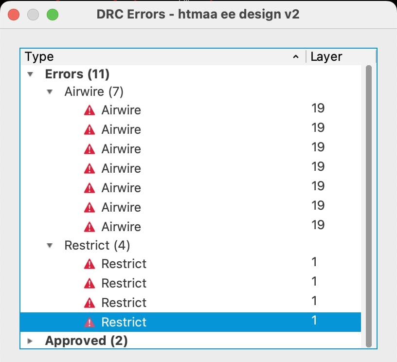
After this was the process of placing and routing all the components on the actual PCB. This was extremely difficult for me and extremely frustrating--it felt like literally every net crossed over eachother. in the PCB interface in Eagle, airwires are placed between components that were logically connected in the schematic, which made the process slightly easier. I used a lot of 0 ohm resistors in order to connect a lot of the components and wires. Another important and useful tool is the design rule check, or drc, and can be used to ensure that your board follows the design rules regarding the placement of wires and components. Eagle integrates this very nicely, and is great for checking on your routing as you're placing things to make sure that you're placing wires and components such that the shop PCB mill can actually mill them, as well as just having enough space for soldering. Below is an example of the file corresponding to the design rules, and the checker in action.

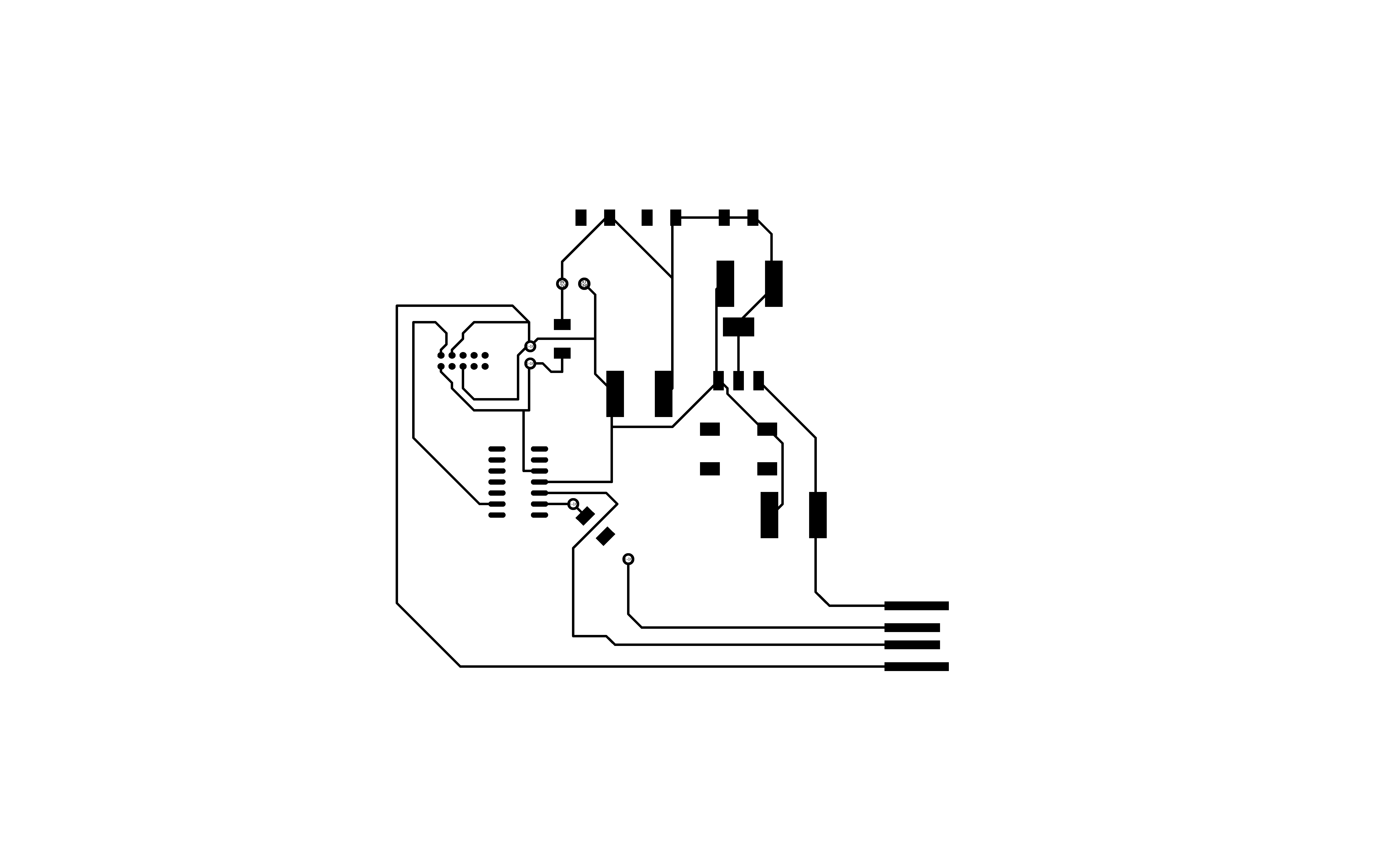
After connecting all the components and resolving the above issues, as shown in the design rule check, I was able to finish my PCB schematic and prepare it for printing.
I created a png file with my traces in black (which is the part that gets milled away), as well as another png file with the interior of the chip filled in white for the outline.
 After this was actually milling the traces and outline. I transferred my png files to a usb to upload my images to mods.