11. October 2022
Electronics Design
For this week’s assignment, I designed a PCB using the “hello.D11C.blink” design as reference in EAGLE (I added a button to the design).
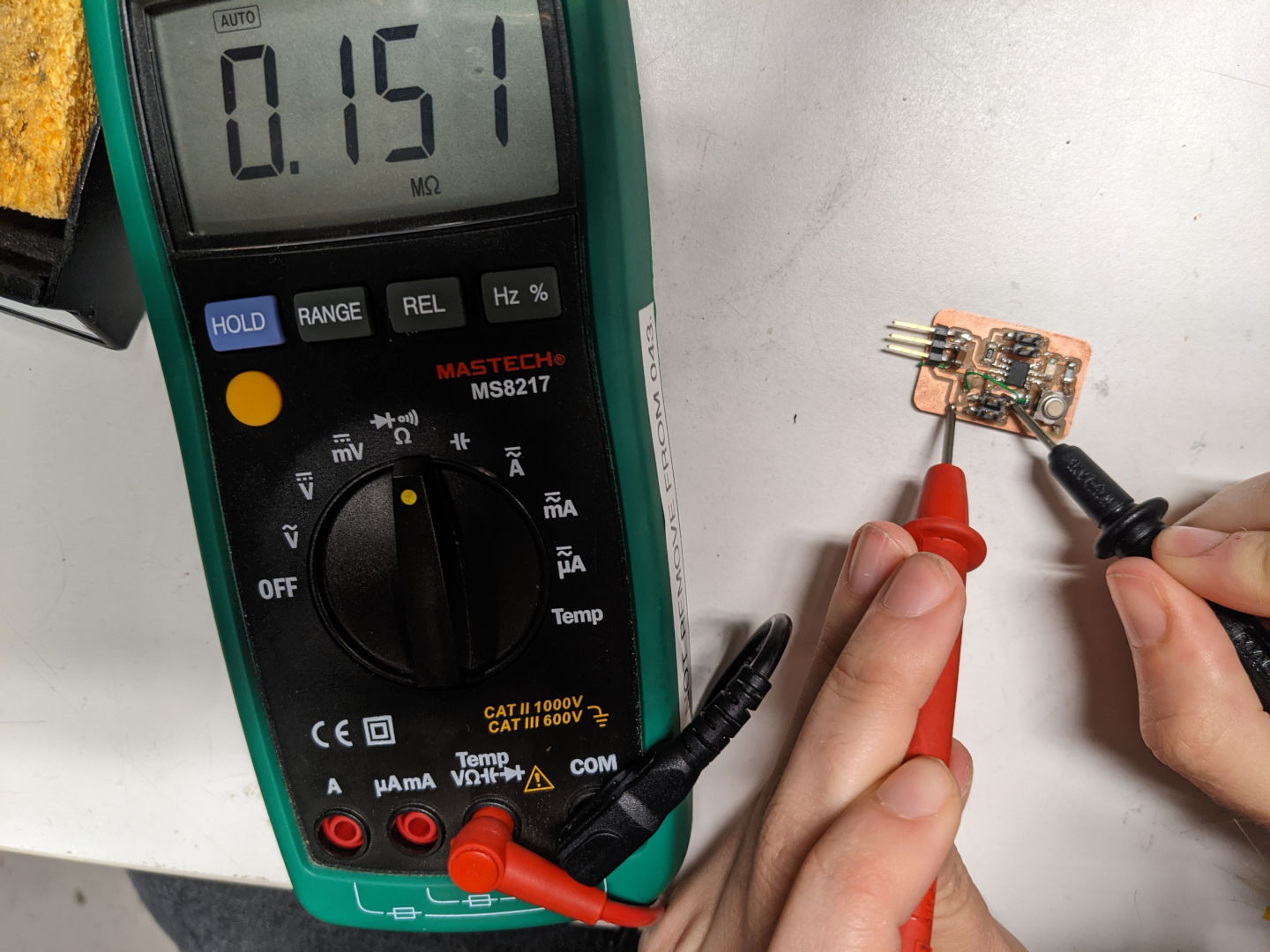
Testing a Board
As part of the group assignment, we used a multimeter, as well as an oscilloscope to test the wiring of a microcontroller circuit board we found in the lab. We measured the voltage across components to identify the different paths of the circuit. We also used resistance measurements to determine which nodes are connected.
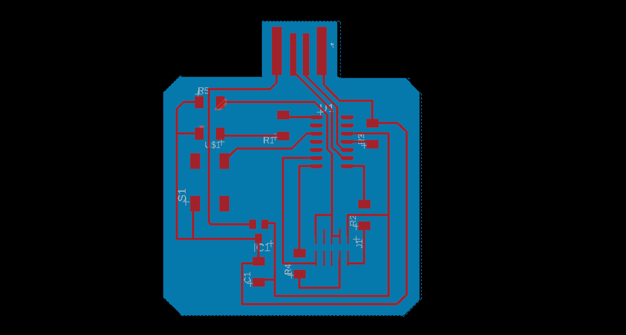
Design
This was my first time using EAGLE, but the learning curve was not too bad. I began by drawing a schematic. Initially, I did not know the pins on the microcontroller and programming headers were well-defined and needed to be used for Reset, Clock, etc., specifically. As such, I needed to rewire the components several times, but finally I got a design that worked.
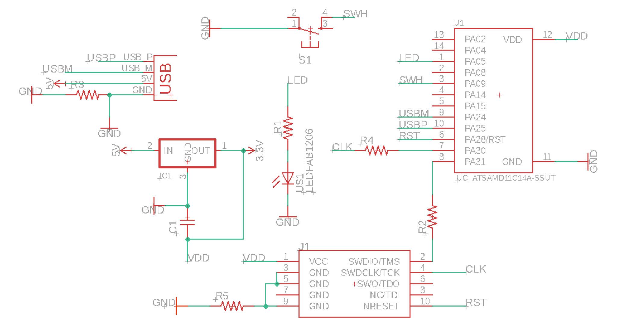
When trying to lay out the components on the board, I realized I needed to add numerous jumpers as the paths could not be entangled. Hence, I added four 0 Ohm resistors to my design. Finally, I traced the outline of the board, taking extra care to ensure the USB stick would fit in the port.
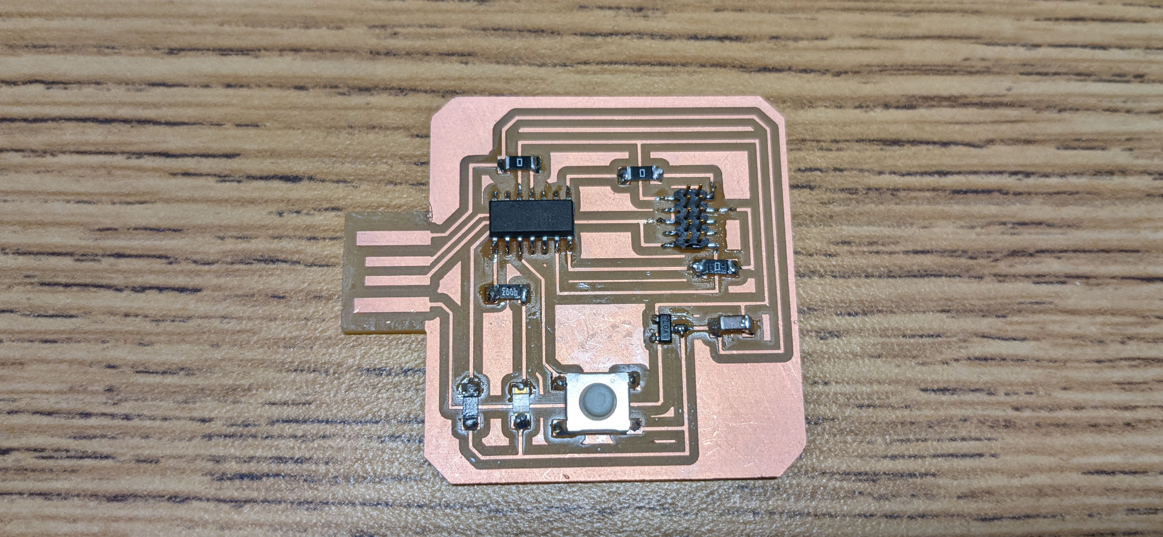
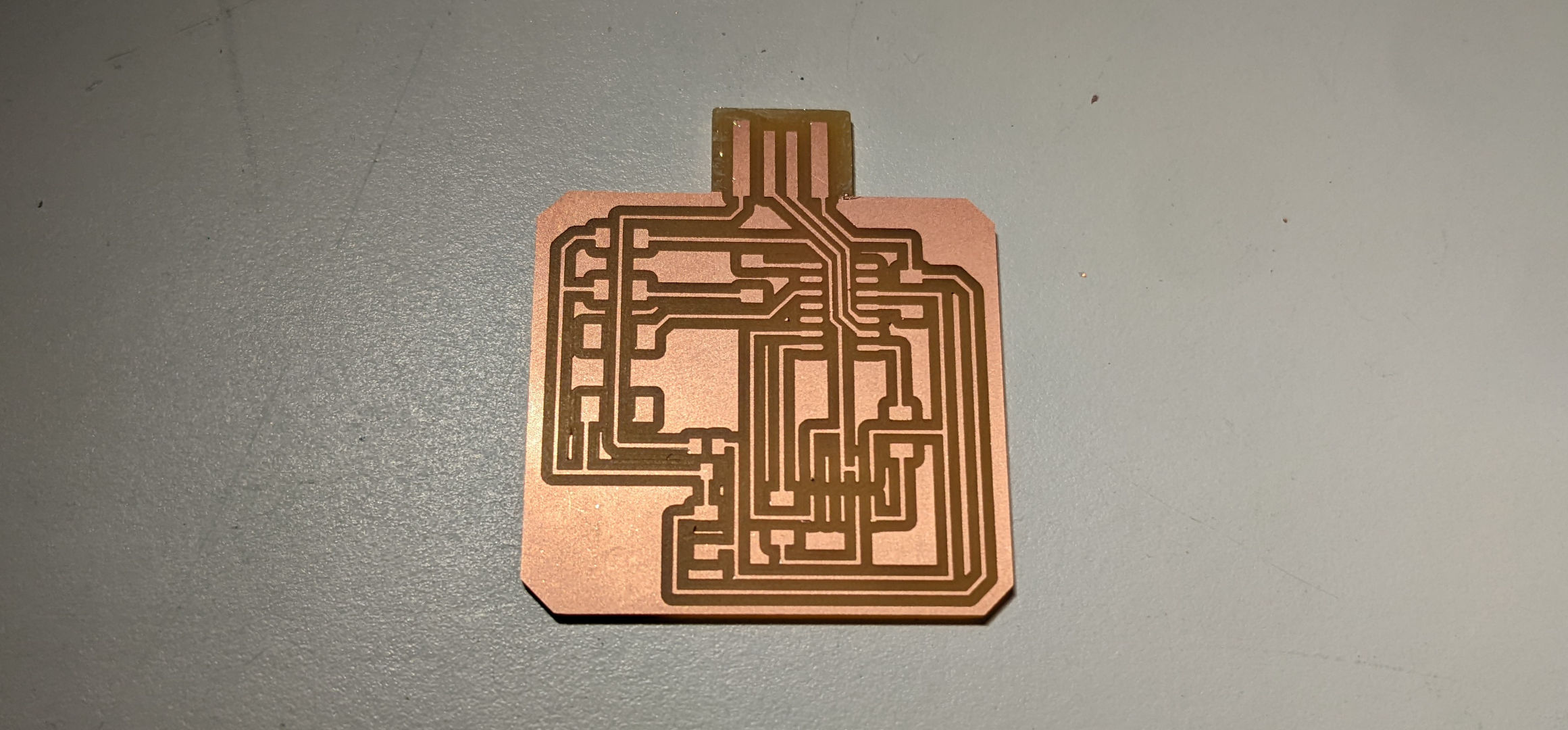
Milling
Several people in the lab struggled with getting the copper board to not move while the machine was milling. As such, I made sure to tape the board down extra strongly when it came my time to mill. The results looked very good!
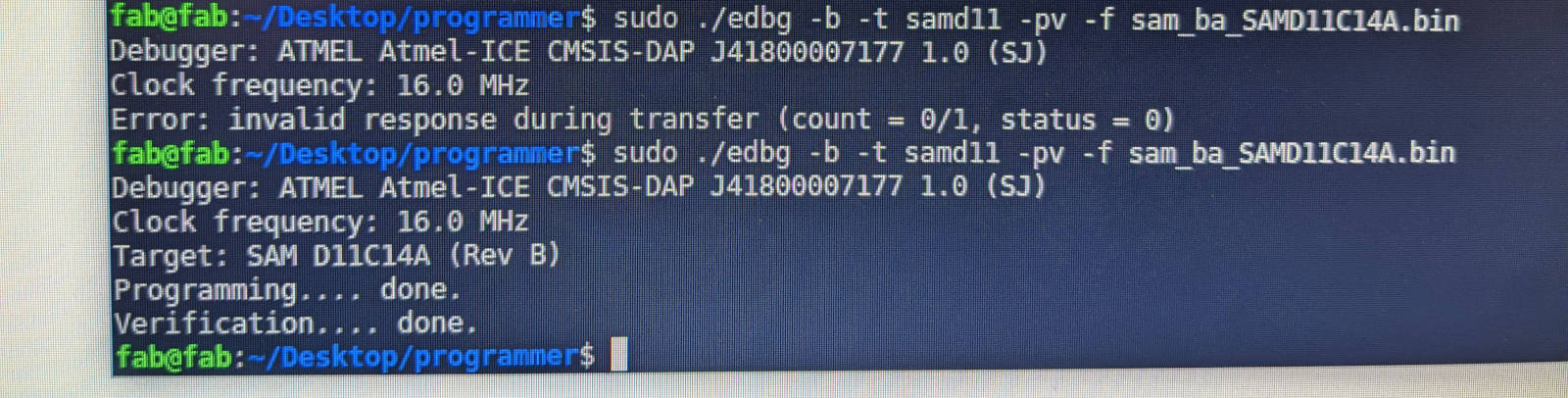
After the board was milled, I stuffed it with the components (which took less than 30 minutes!) and tested it. I plugged my board into the computer and got a signal.
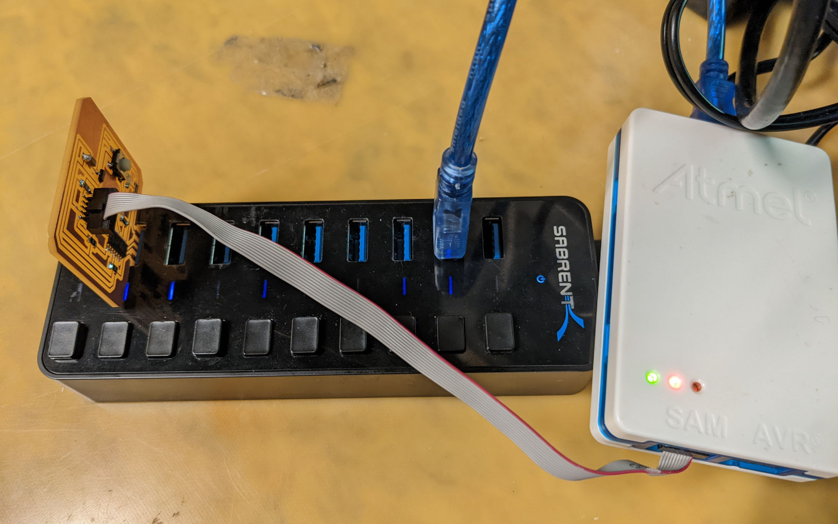
Finally, I loaded the bootloader successfully! Looking forward to Week 6, where we learn to program the boards!